EN
1
Warnings:
For product installation, maintenance and repairs contact only qualified
technical personnel, who must comply with the legislation in force.
Read the instructions carefully and verify which motors or con-
trol units are suitable for use with this weather sensor. Any other
application is improper and prohibited.
The weather sensor measures WIND speed in Km/h, and the brightness
of sunlight in KLux.
It can be used to command programmed motors or control units, ena-
bling the automation of awnings, rolling shutters and similar fixtures via a
radio control, based on the detected weather conditions.
For example, awnings will open automatically when the programmed
SUNLIGHT level is exceeded, and will close when the WIND level is
exceeded.
The commands are sent by radio, therefore the only connections
required are the electric line ones (see the “Installation” chapter).
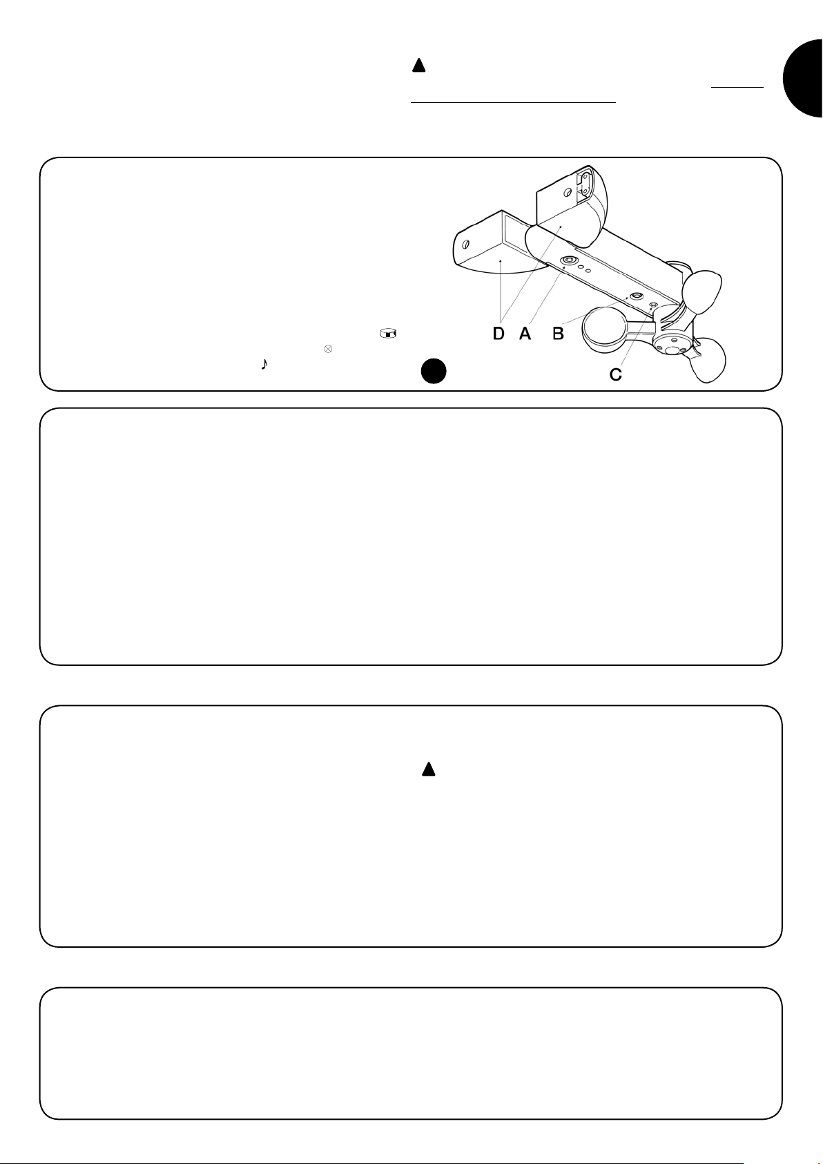
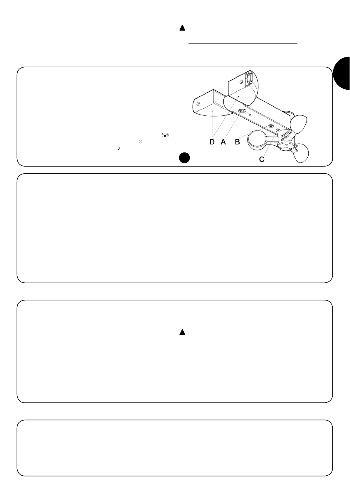
The sensor is equipped with a programming/transmission button ( )
(Fig. 1, detail B) and a multicoloured indicator light (Led ) (Fig. 1, detail
C). It also features an audible signal (Beep ).
1) Product description
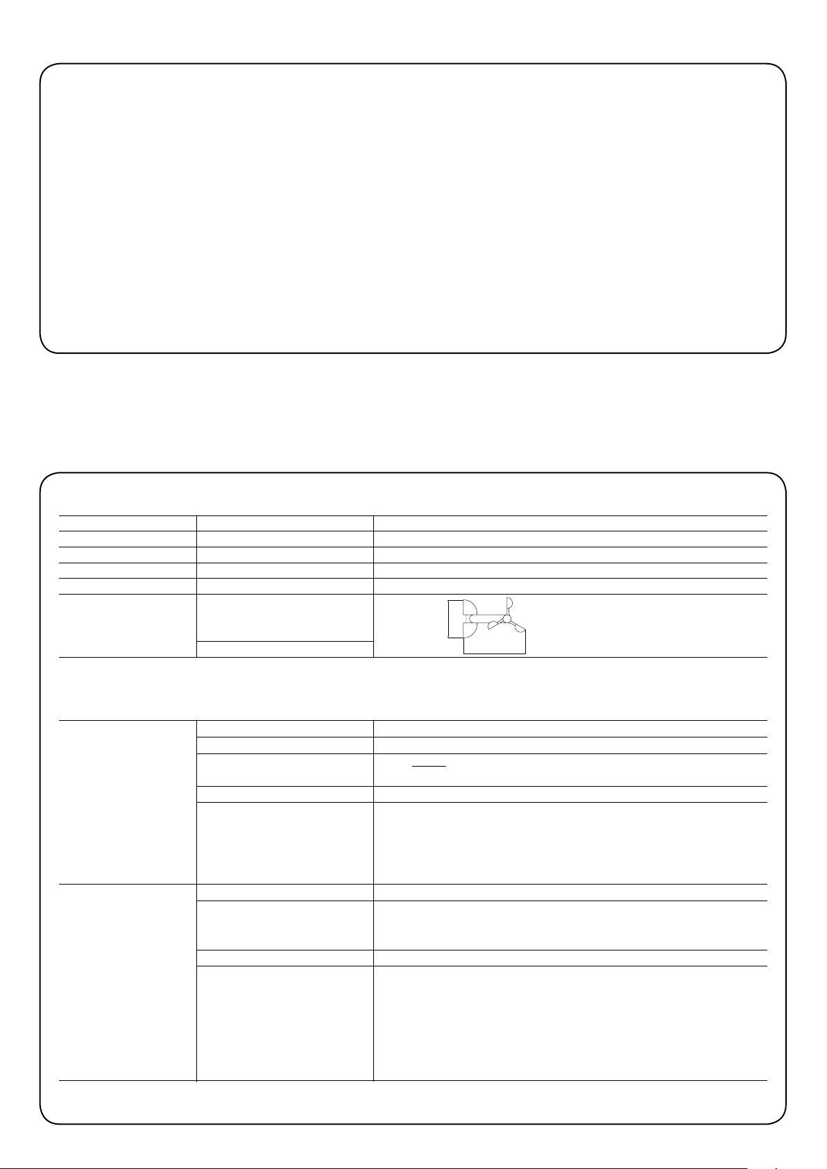
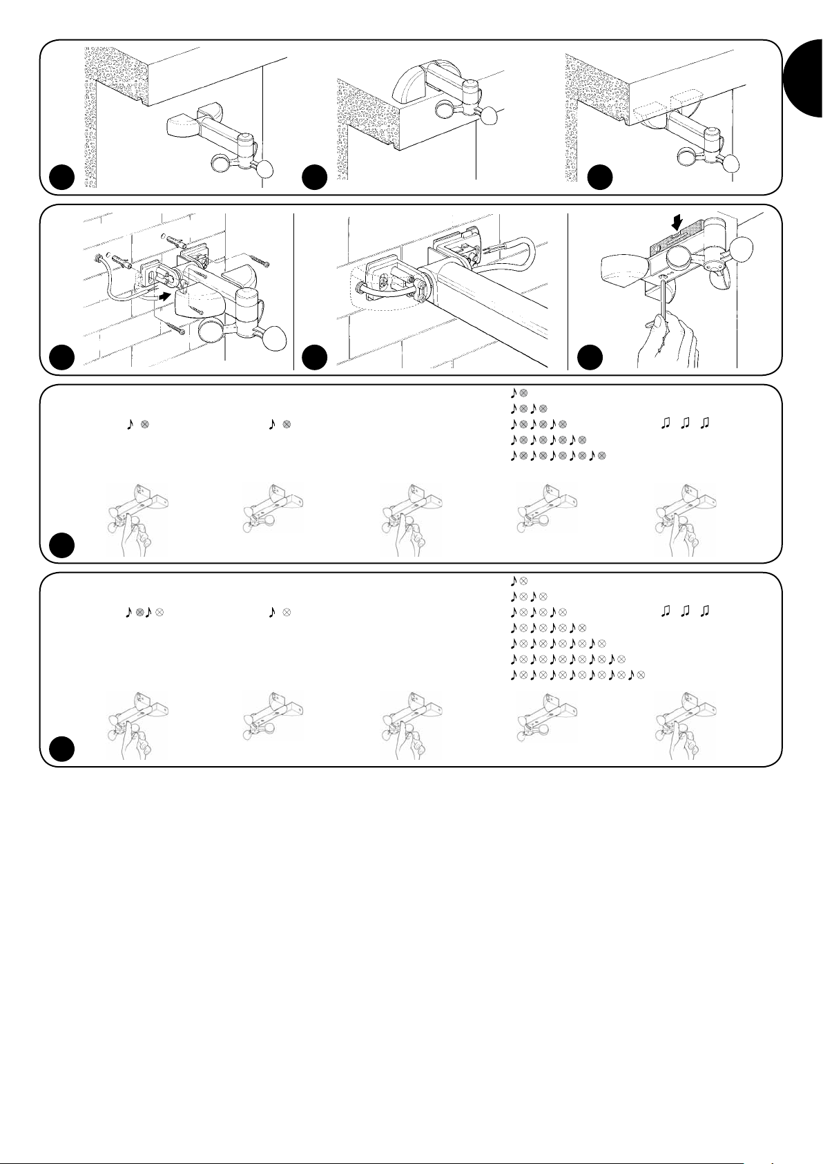
2) Installation
Before you install the unit, test the radio range, as the presence of thick
walls and/or other devices operating at the same frequency can greatly
reduce the range. To check the range, carry out a provisional test (see
“Testing” chapter), positioning yourself, first, near the automation and
then near the place of final installation.
Though the range under favourable conditions, in a free field, can be
100-200 m, taking into account the protection function, we advise you
not to exceed 20-30 m. Moreover, you should make sure that there are
no other devices operating at the same frequency and with continuous
transmission, such as alarms, headphones, etc., which might further
reduce the range.
For proper operation, keep in mind that the weather sensor must be
positioned near the shutter/awning to be protected, in an area that is
exposed to the action of the wind and sun.
To proceed with the installation, refer to Fig. 2, Fig. 3, Fig. 4 and Fig. 7;
remember not to tighten the fastening screw too hard (Fig. 1, detail A).
As The sensor is supplied with mains voltage, we recommend
that you do not install it in an easily accessible location.
!
3) Electrical connections
The product must be connected to a 230Vac without ground connection,
as shown in Fig.5, Fig.6 and Fig.7.
After wiring, close the covers on the mounting bracket securely (Fig.1
detail D).
!
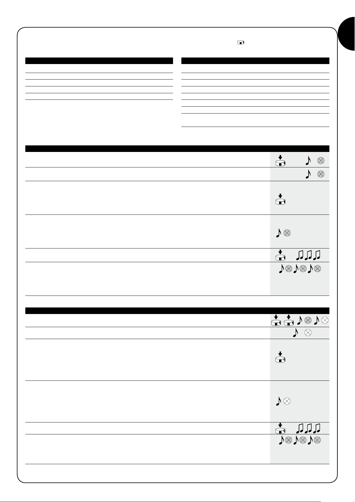
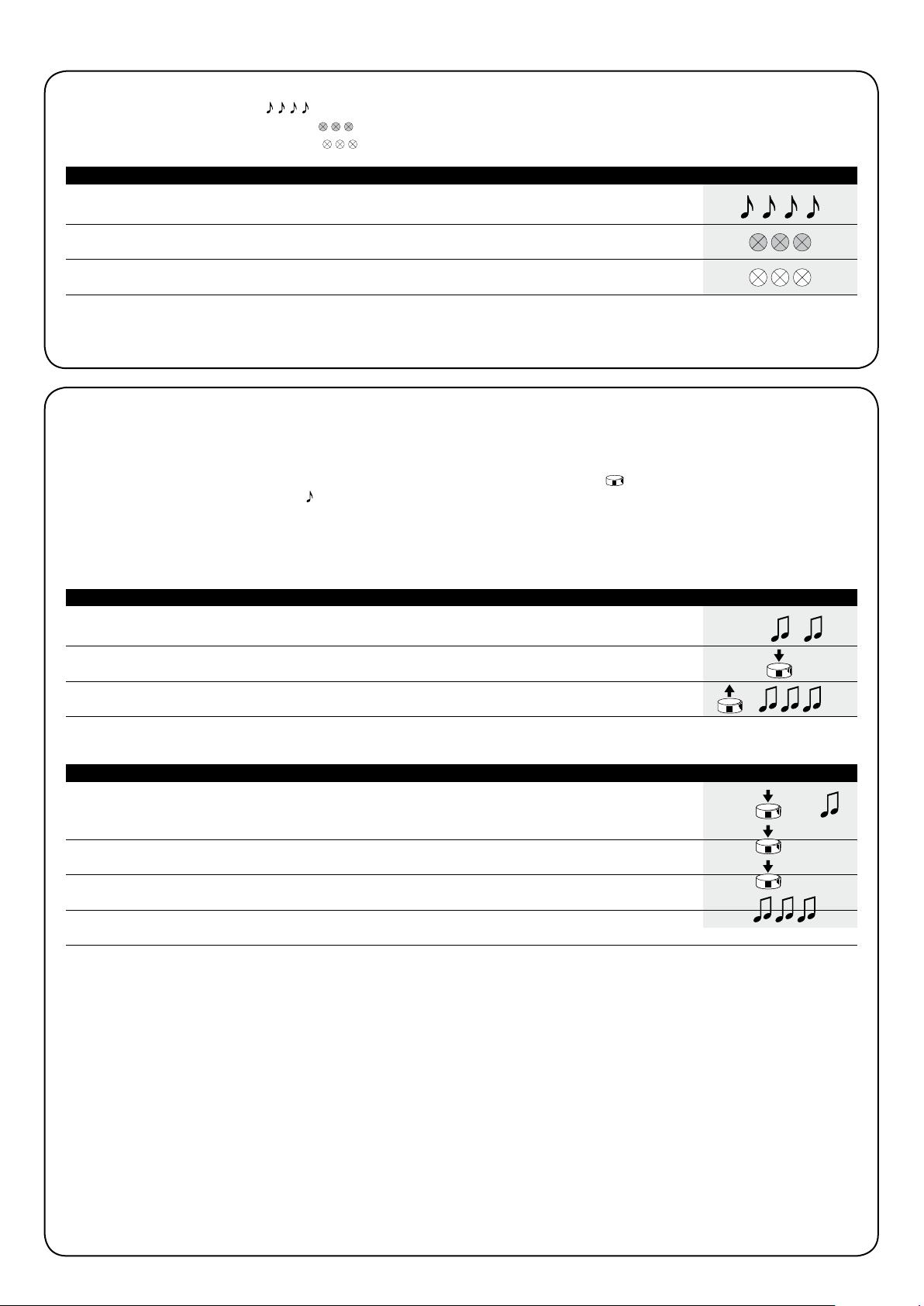
1.1) Command rules
The sensor measures WIND speed and brightness of SUNLIGHT. When
the detected value exceeds the programmed level, a command is sent
to the motors or control units as described below:
Wind: when the WIND level is exceeded for a period of at least 3 sec-
onds, an “up” command (corresponding to button son the remote con-
trols) is sent. When the threshold value is exceeded, the LED becomes
red and while the command is being transmitted, the RED LED flashes.
Sun: when the SUN level is exceeded for a period of at least 2 minutes, a
“down” command (corresponding to button ton the remote controls) is
sent. When the threshold value is exceeded, the LED becomes GREEN
and while the command is being transmitted, the GREEN LED flashes.
Precedence: if both levels are exceeded, precedence is given to WIND
before SUN for safety reasons. Only after the WIND level has dropped
below the set value for at least 2 minutes, the SUN command is enabled.
Each command is repeated at periodic intervals until the SUN/WIND level
drops below the set limits.
The sensor transmits the measured WIND speed in Km/h, brightness
of SUNLIGHT in Klux, plus RAIN*, TEMPERATURE* and HUMIDITY*
readings.
(*= only for versions with special sensor)
1