HunterDouglas ALPHA Series Instruction Manual

11/2019
ALPHA AWNING
SERIES
INSTALLATION AND MEASURING GUIDELINES
(INCLUDES THE SRS V2)

Page 2
MEASURING AND INSTALLATION MANUAL ONLY.
PLEASE REFER TO YOUR ONLINE PORTAL FOR THE
UPDATED VERSION.
This Product Manual is only a guide to the measurement and installation.
Hunter Douglas Limited does not warrant the accuracy contained in this manual.
The information contained in this Product Manual is based on the measurement and installation
data known to us at the time of issue of the Product Manual and is therefore subject to changes
or amendments at any time without notice, and the right to change or amend is hereby expressly
reserved by Hunter Douglas Limited.
IMPORTANT
This Product Manual at all times remains the property of Hunter Douglas Limited.
Its contents are strictly confidential and may not be reprinted, copied, reproduced or multiplied in any
form. This Product Manual must be maintained in its original form and must be returned to Hunter
Douglas Limited upon first request. Hunter Douglas Limited is not responsible to you or anyone else
for any loss suffered in connection with the use of this product manual or any of the content.
Hunter Douglas Limited
Australia
PRODUCT MANUAL
INFORMATION
© Copyright 2019 Hunter Douglas Limited [ABN 98 009 675 709] •18.016.085 •11/19
® Registered Trade Marks of Hunter Douglas Limited Somfy is a registered trade mark of SOMFY Pty Limited
DISCLAIMER ISSUED: NOVEMBER 2019
SAFETY & WARNING ADVICE
ALPHA AWNING SERIES INSTALLATION MANUALALPHA AWNING SERIES INSTALLATION MANUAL

Page 1
Contents
Safety and Warning Advice + General Advice .... 2
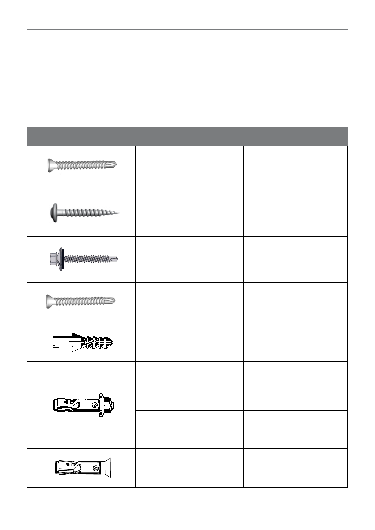
Fixings .......................................................... 3
Characteristics of Awning Fabrics................... 4
Options and Limitations .................................. 5
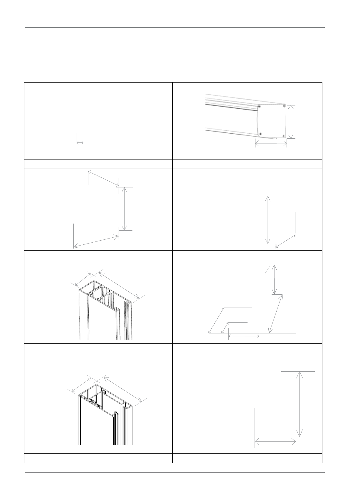
Component Dimensions ................................. 6
INSTALLATION
Open Roller Installation................................ 7
• Flow Chart..........................................................7
• Installation Instructions........................................8
Headbox Installation ................................... 9
• Flow Chart .........................................................9
• Installation Instructions.....................................10
Installing the Roller Tube........................... 12
• Flow Chart .......................................................12
• Installation Instructions.....................................13
ALPHA Straight Drop Awning ................... 15
• Exploded view diagram....................................15
• Flow Chart .......................................................16
• Installation Instructions.....................................17
ALPHA Cable Guide Awning .................... 18
• Exploded view diagram....................................18
• Flow Chart .......................................................19
• Installation Instructions.....................................20
ALPHA SRS V2 (Side Retention System)
Awning ....................................................... 22
• Exploded view diagram....................................22
• Flow Chart .......................................................23
• Installation Instructions.....................................24
ALPHA Deep Channel Awning ................. 30
• Exploded view diagram....................................30
• Flow Chart .......................................................31
• Installation Instructions.....................................32
ALPHA Pivot Arm Awning ......................... 34
• Exploded view diagram....................................34
• Flow Chart .......................................................35
• Installation Instructions.....................................36
Pretensioning the Spring for Literise/Light Lift
Pretensioning the Spring for Literise/Light Lift.....38
Pretension Chart.......................................... 39
ALPHA Linking Option .............................. 40
• Exploded view diagram....................................40
• Flow Chart .......................................................41
• Installation Instructions.....................................42
USER INFORMATION
Operating Instructions .................................. 46
MEASURING INSTRUCTIONS
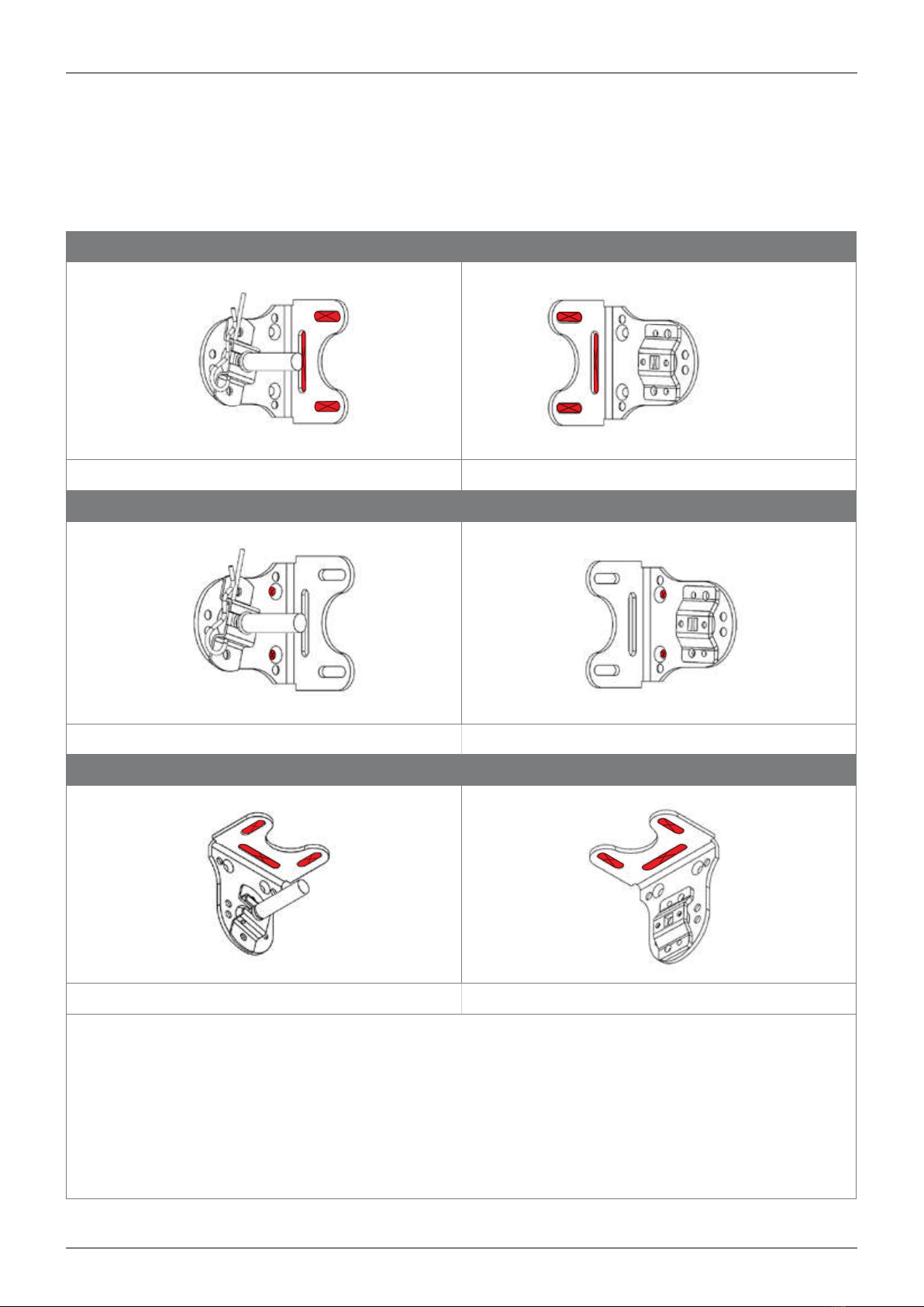
On Face Architrave....................................... 46
Reveal and Top Fix (Side Fix) ........................ 48
ALPHA AWNING SERIES INSTALLATION MANUAL

Page 2
A minimum of 2 people are necessary for proper installation.
PLEASE NOTE:
Installation fixings will NOT be supplied with any of the ALPHA Awning Series.
Please refer to fixing section. Each installation should be assessed on a case by case scenario.
WARNING! – The brackets must be fixed solidly to a substantial surface. Hollow bricks or foam
products are not suitable. Brick veneer surfaces require at least 2 courses of brickwork above the
bracket and 2 courses below.
GENERAL ADVICE
The electrical data is shown on the label of electric operating awnings.
Tools: The following tools are required for installation:
• Level
• Battery Drill
• Screwdrivers
• Hammer Drill
• Drill Bits
• Spanner - 7mm (size of open end spanner for top aligner)
• Allen Key
SAFETY AND WARNING ADVICE
ALPHA AWNING SERIES INSTALLATION MANUAL

Page 3
Due to possible differences in specification, application and interpretation of results, users must
make their own evaluation of the product to determine the suitability of fixings and their intended
use.
ITEM TITLE DESCRIPTION
Counter Sunk (Zenith)
10g x 50mm
Available in Metal or Timber thread
Stainless
Used to side fix channels.
Waffer/Button Head (Buildex)
8g x 50mm
Available in Metal or Timber thread
Used to face fix channels.
Roofing & Cadding
Hex Head (Buildex)
12g x 50mm
Available in Metal or Timber thread
Used to fix universal brackets.
Counter Sunk (Zenith)
10g x 50mm
Available in Metal or Timber thread
Stainless
Used to fix wire guide bottom
bracket.
Ramplug/Green Plug (Ramset)
50mm Length Used to fit to brick or concrete
Dyna Bolt (Ramset)
6m x 30mm Used to face fix channels.
Dyna Bolt (Ramset)
8mm x 50mm Used to fix universal brackets.
Counter Sunk (Ramset)
4.5mm x 30mm
Stainless
Used to fix wire guide bottom
bracket.
FIXINGS
ALPHA AWNING SERIES INSTALLATION MANUAL

Page 4
CHARACTERISTICS OF AWNING FABRICS
Some slight fabric curling may occur on fabric edge on large applications, whilst the following
characteristics are considered normal occurrences.
• Creasing (Figs. 1, 2)
• Puckering (Figs. 3, 4 & 5)
• Tension Induced Stretching (Figs. 6)
Conditions apply. See www.hunterdouglas.com.au for Warranty document.
WARRANTY
ALPHA AWNING SERIES INSTALLATION MANUAL

Page 5
CRANK GEAR MOTORISED INTERNAL CORD
OVERALL MAX WIDTH 5000mm 5000mm 3500mm
OVERALL MAX DROP 4000mm 4000mm 2900mm
OVERALL MIN DROP 300mm 300mm 300mm
MAX AREA 16 Sqm 16 Sqm 10 Sqm
MEASURING INSTRUCTIONS
Accurate measuring of the ALPHA Awning Series is vital for successful fitting and consequential
use. The product can be fitted on Face, Side or Ceiling fixing applications and can be operated by
crank, cord or motorised.
2mm deduction for Reveal Installs
Face Fit Supplied Overall Size
+/- 2mm Manufacturing Tolerance
OPTIONS AND LIMITATIONS
ALPHA AWNING SERIES INSTALLATION MANUAL

Page 6
COMPONENT DIMENSIONS
CABLE GUIDE HEADBOX
UNIVERSAL INSTALLATION BRACKET BOTTOM RAIL
DEEP CHANNEL BOTTOM CABLE BRACKET
ALPHA SRS V2 PIVOT ARM FRONT RAIL
125mm
130mm
50mm
30mm
100mm
68mm
100mm
50mm
33mm
30mm
16mm
37mm
23mm
52mm
33.5mm
81mm
37.5mm
73mm
14.7mm
ALPHA AWNING SERIES INSTALLATION MANUAL

Page 7
OPEN ROLLER INSTALLATION
STEP 2 - DRILL FIXING HOLES
STEP 3 - INSTALL THE FIRST BRACKET
STEP 1 - MARK FIXING HOLES FOR THE FIRST BRACKET
STEP 4 - MEASURE OVERALL WIDTH
STEP 5 - REPEAT STEPS 1,2 & 3 FOR
THE SECOND BRACKET
ALPHA AWNING SERIES INSTALLATION MANUAL

Page 8
STEP 1/2/3 - FACE FIT INSTALL
IDLE END DRIVE END
REVEAL FIT INSTALL
IDLE END DRIVE END
CEILING FIT INSTALL
IDLE END DRIVE END
Brackets will come pre-assembled with idle and drive end components attached. The orientation of these components
on the brackets will be determined by the fixing orientation specified on the order form. Example: Face/Reveal, Ceiling.
- Mark the fixing holes for the first bracket.
- Drill holes to suit the method of fixing determined by the substrate being fixed to.
- Screw the first bracket in place. Ensure the bracket is installed straight using a spirit level. If required, pack out
the bracket.
- Repeat process for the second bracket.
- Ensure both brackets are installed level and the distance apart is enough for the roller tube to be inserted. The
distance between the brackets should be the ordered overall measurement from outside of bracket to outside of
bracket.
OPEN ROLLER INSTALLATION
ALPHA AWNING SERIES INSTALLATION MANUAL

Page 9
HEADBOX INSTALLATION
STEP 2 - REMOVE ROLLER TUBE
STEP 3 - MARK & PRE DRILL HEADBOX BACK PANEL
- MARK FIXING HOLES ON INSTALLATION SURFACE
- DRILL FIXING HOLES ON INSTALLATION SURFACE
- INSTALL HEADBOX THROUGH BRACKETS
STEP 1 - OPEN THE HEADBOX
ACCESSORIES
INSTALLATION SPREADER PLATE
PLEASE REFER TO RELEVANT SECTION FOR INSTRUCTIONS
ALPHA AWNING SERIES INSTALLATION MANUAL

Page 10
STEP 1 - OPEN THE HEADBOX STEP 2 - REMOVE ROLLER TUBE
Open the headbox front cover by unscrewing the bottom
screw on the headbox end cap. Repeat on opposite side.
NOTE: For reveal fit the screw is no longer required.
Pull out the idle end locking pin and remove the roller
tube idle end first.
STEPS 3 - FACE FIT
IDLE END DRIVE END
STEPS 3 - REVEAL FIT INSTALL
IDLE END DRIVE END
HEADBOX INSTALL
ALPHA AWNING SERIES INSTALLATION MANUAL

Page 11
STEPS 3 - CEILING FIT INSTALL
IDLE END DRIVE END
Mark and drill the head box back plate where the fixings will go.
NOTE: Always secure the headbox back panel through the installation brackets or spreader plate!
• After determining the exact position of the headbox you can fasten the brackets and headbox on the installation
surface.
• Mark the fixing holes for the first bracket.
• Drill holes to suit the method of fixing determined by the substrate being fixed to.
• Secure installation screw in bracket to hold one side of head box.
• Repeat the process for the opposite bracket and ensure that the head box is straight using a spirit level.
NOTE: If required pack out the headbox.
• Once satisfied the headbox is level, secure remaining fixing points.
NOTE: For awnings over 3500mm wide, add an additional fixing point through the centre of the headbox back panel.
E.g 3500mm wide secure at 1750mm.
ACCESSORIES REVEAL FIT - HEADBOX COVER INSTALL
6.0mm
D4.5mm
D4.5mm
6.0mm
45mm
SPREADER PLATE OPEN HEADBOX CLOSED HEADBOX
If there is no substantial fixing point at the ends
of the headbox, a Spreader Plate can be added.
This allows 250mm of flexibility for installation
points at each end of the awning. If a spreader
plate is ordered, this will come preassembled to
the bracket inside the headbox determined by the
installation type specified. Secure through Fixing
points highlighted in the image.
A 4.5mm hole needs to be drilled in the headbox cover in
REVEAL applications. Location of hole, refer to diagram above.
ALPHA AWNING SERIES INSTALLATION MANUAL

Page 12
INSTALLING THE ROLLER TUBE
STEP 2 - INSTALL THE IDLE END
OPTIONAL: STEP 3 - ATTACH THE HEADBOX FRONT COVER
STEP 1 - INSTALL THE DRIVE END
OPTIONAL: INTERNAL TAPE WINCH INSTALLATION
INSTRUCTIONS
ALPHA AWNING SERIES INSTALLATION MANUAL

Page 13
STEP 1 i- MOTORISED STEP 1 ii - CRANK
Motorised – Insert motor into motor bracket then secure using
motor clip Crank – insert crank pin into crank gear
STEP 1 iii - INTERNAL TAPE WINCH STEP 2 A - INSERT PIVOT PIN
Internal Tape Winch – Insert pin into spring plate and use locking
pin to secure. Insert Pivot Pin into idle end on tube.
STEP 2 B - INSTALL THE ROLLER OPTIONAL: STEP 3 - ATTACH THE
HEADBOX FRONT COVER
Lift Roller over the installation bracket and down so pivot pin sits
inside the pivot plate. Insert idle locking pin to secure roller.
*Operate the awning a couple of times to ensure tracking and cor-
rect operation of the awning.
Once satisfied, reattach the headbox front
cover.
INSTALLING THE ROLLER TUBE
ALPHA AWNING SERIES INSTALLATION MANUAL

Page 14
INTERNAL TAPE WINCH INSTALL INSTRUCTIONS
Page 19
ALPHA SERIES INSTALLATION MANUAL
INTERNAL TAPE WINCH INSTALL INSTRUCTIONS
Fitting Internal Tape Winch
- Unscrew the cover of the internal tape winch and note the direction in which the tape runs off the spool.
- Remove the tape supplied with the winch.
- Thread the tape from the awning tape spool through the two swivel tape guides. Attach swivel tape guides to the
internal and external walls. Lower the awning.
- Thread the end of the tape through the slot on the tape winch spool. Cut the tape so that only 1 - 2 windings will
remain on the spool. Tie a secure knot in the end. Wind the excess tape on to the spool. Replace the spool in the winch
ensuring that the tape winds off in the correct direction. Screw cover back on to winch.
- Drill four (4) holes in the wall for the winch and fit rawl plugs supplied or use the fastener appropriate for the
installation. At least two of the screws should be set into an architrave or stud. All four screws must be used. If
necessary add packing behind the winch if attaching to an uneven surface.
- Test the awning to see if it functions properly.
Fitting Internal Tape Winch
- Unscrew the cover of the internal tape winch and note the direction in which the tape runs off the spool.
- Remove the tape supplied with the winch.
- Thread the tape from the awning tape spool through the two swivel tape guides. Attach swivel tape guides to the
internal and external walls. Lower the awning.
- Thread the end of the tape through the slot on the tape winch spool. Cut the tape so that only 1 - 2 windings will
remain on the spool. Tie a secure knot in the end. Wind the excess tape on to the spool. Replace the spool in the
winch ensuring that the tape winds off in the correct direction. Screw cover back on to winch.
- Drill four (4) holes in the wall for the winch and fit rawl plugs supplied or use the fastener appropriate for the
installation. At least two of the screws should be set into an architrave or stud. All four screws must be used. If
necessary add packing behind the winch if attaching to an uneven surface.
- Test the awning to see if it functions properly.
ALPHA AWNING SERIES INSTALLATION MANUAL

Page 15
*000 - MILL, 100 -SILVER PEARL, 134-MOMBASA, 734-YALUMBA, 737-CHARDONNAY, 810-THUNDERCLOUD, 850-WHITE SATIN
4
1
3
2
56
7
89
10
11
12
13
14
16
15
17
19
18
No Part Description
1 46.608.XXX HEADBOX END CAP LH & RH
2 46.005.XXX HEADBOX BACK PLATE
346.012.XXX*
46.013.XXX*
R HEADBOX FRONT COVER (CLOSED)
R HEADBOX FRONT COVER (OPEN)
4 46.019.XXX 100MM UNIVERSAL BRACKET
5 46.002.XXX PIVOT PIN & PLATE
6
46.506.000
44.210.000
46.507.000
60MM IDLE END
70MM IDLER WITH HOLE
78MM IDLE END
7
42.180.049
46.522.500
46.522.700
46.521.500
46.521.700
60MM TUBE
70MM TUBE 5MT
70MM TUBE 7MT
78MM TUBE 5MT
78MM TUBE 7MT
8
42.603.855
44.209.000
46.504.000
46.505.000 6.
60MM DRIVE END - SMALL
70MM DRIVE END
78MM CRANK DRIVE END
60MM DRIVE END - 13MM SHAFT
ALPHA STRAIGHT DROP
No Part Description
9 46.502.XXX 9:1 GEAR
10 46.524.000 PLAIN BOTTOM RAIL END CAP
11 46.517.000 R BOTTOM RAIL LOCKING PIN
12 46.500.000 HOLD DOWN CLIP
13 42.236.000 BUCKLE FOR HOLD DOWN STRAP
14 42.230.000 RUA STRAP
15 42.204.000 BREECHING STAPLE
16 46.011.XXX R BOTTOM RAIL
17 82.29X.XXX
44.XXX.XXX
CANVAS FABRIC
EXTERNAL SCREEN FABRIC
18 44.132.000
42.421.855
4.2MM ES SOLID SPLINE
6MM SPLINE
19 42.198.000
42.421.855
3.5MM HARD SPLINE
6MM SPLINE
ALPHA AWNING SERIES INSTALLATION MANUAL

Page 16
ALPHA STRAIGHT DROP AWNING INSTALLATION
STEP 2
INSTALL ROLLER TUBE (pg12)
STEP 3
i - INSTALL HOLD DOWN STRAPS (pg17)
ii - INSTALL LOCKING BOLTS (pg17)
STEP 1
i - OPEN ROLLER INSTALL (pg7)
ii - HEADBOX INSTALL (pg9)
ALPHA AWNING SERIES INSTALLATION MANUAL

Page 17
STEP 1 - INSTALL HEADBOX OR OPEN ROLLER STEP 2 - INSTALL THE ROLLER TUBE
Refer to the following sections for instructions
i - open roller install (pg7)
ii - headbox install (pg9)
refer to installing the roller section (pg12)
STEP 3 - INSTALL HOLD DOWN STRAPS
In order to protect the hold down clips they will be supplied uninstalled from the bottom rail.
- Remove Bottom Rail end cap
- Insert ALL Hold down clips with strap, buckle and dog clip attached.
- Lower awning to desired fixing height.
- Slide hold down clips and straps to desired hold down locations.
- Reattach bottom rail end cap.
- Fix breeching staple to floor or wall surface under hold down straps.
- Use dog clip to attach hold down to breeching staple.
STEP 3 ii - INSTALL LOCKING BOLTS TO
REVEAL POST
STEP 3 iii - INSTALL LOCKING BOLTS USING
BREECHING STAPLE
The locking bolts will be supplied pre-installed in the
bottom rail
Secure to Reveal post
- Lower awning to desired fixing height.
- Slide locking bolts out to desired fixing location
- Line up locking bolts with the posts and ensure the
bottom rail is level.
- Mark fixing holes on post and drill using a 12mm drill
bit.
- Slide locking bolts into the hole and apply tension to
ensure a level installation.
- Holes can be drilled at a variety of different stopping
locations along the post dependent on consumer
requirements
The locking bolts will be supplied pre-installed in the
bottom rail
Secure using Breeching Staple
- Lower awning to desired fixing height.
- Slide locking bolts out to desired fixing location
- Place breeching staple to floor or wall surface to
ensure the locking bolt can be secured under the
breeching staple.
- Ensure the bottom rail is level. If not, pack out
breeching staple to ensure bottom rail will be perfectly
horizontal when secured.
- Fix breeching staple to floor or wall surface.
- Slide locking bolts into the hole and apply tension to
ensure a level installation.
ALPHA STRAIGHT DROP AWNING INSTALLATION
ALPHA AWNING SERIES INSTALLATION MANUAL

Page 18
ALPHA CABLE GUIDE AWNING
*000 - MILL, 100 -SILVER PEARL, 134-MOMBASA, 734-YALUMBA, 737-CHARDONNAY, 810-THUNDERCLOUD, 850-WHITE SATIN
1
4
3
2
56
7
9
8
10
11
12
13
14
16
15
18
No Part Description
1 46.608.XXX HEADBOX END CAP LH & RH
2 46.005.XXX HEADBOX BACK PLATE
346.012.XXX*
46.013.XXX*
R HEADBOX FRONT COVER (CLOSED)
R HEADBOX FRONT COVER (OPEN)
4 46.019.XXX 100MM UNIVERSAL BRACKET
5 46.002.XXX PIVOT PIN & PLATE
646.506.000
44.210.000
46.507.000
60MM IDLE END
70MM IDLE END
78MM IDLE END
742.180.049
46.522.500
46.522.700
46.521.500
46.521.700
60MM TUBE
70MM TUBE 5MT
70MM TUBE 7MT
78MM TUBE 5MT
78MM TUBE 7MT
842.603.855
44.209.000
46.504.000
46.505.000
60MM DRIVE END - SMALL
70MM DRIVE END
78MM CRANK DRIVE END
60MM DRIVE END - 13MM SHAFT
No Part Description
9 46.502.XXX 9:1 GEAR
10 46.524.000 PLAIN BOTTOM RAIL END CAP
11 46.108.063 CG CABLE GUIDE SET
12 46.530.063 EXTENSION PLATE
13 46.011.XXX R BOTTOM RAIL
14 82.29X.XXX
44.XXX.XXX
CANVAS FABRIC
EXTERNAL SCREEN FABRIC
15 44.132.000
42.421.855
4.2MM ES SOLID SPLINE
6MM SPLINE
16 42.198.000
42.421.855
3.5MM HARD SPLINE
6MM SPLINE
17 46.520.000 HEADBOX REVEAL CLIP
18 46.517.000 R BOTTOM RAIL LOCKING PIN
ALPHA AWNING SERIES INSTALLATION MANUAL
This manual suits for next models
1
Table of contents
Other HunterDouglas Accessories manuals