Hurco Spin Doctor 400 Guide

www.GETHURCO.com

www.GETHURCO.com
Welcome
Thank you for purchasing Hurco’s Spin Doctor Hydraulic Valve Exerciser. The concept of a boom
operated valve exerciser was developed by Hurco back in 2002. This new generation of valve exercisers
allowed the user to reach a valve in hard to reach areas while taking the effort out of valve exercising.
Safety was first in mind when developing the Spin Doctor. The Spin Doctor uses gas assisted shocks
making it virtually finger tip light and the unique design of the boom absorbs the torque from
operating those tough valves. This product is so unique; it is covered by several US Patents and
other Patents Pending.
Spin Doctor will:
• Operate any size valve from 4” to 60”.
• Depending on model, capable of up to 950 ft. lbs. torque.
• Reach multiple valves in close proximity so the vehicle does not need to be repositioned.
• Reach valves in hard to reach areas.
Hurco Technologies, Inc. would like to take this opportunity to welcome you as a new customer and
user of the Spin Doctor Hydraulic Valve Exerciser. You have just purchased the best valve exercising
system available. The Spin Doctor is simple to use and will provide you with years of service.
This manual will take you through the step by step procedures for using the Spin Doctor. We use
simple to understand instructions and photos to assist you in learning how to get the best results from
your Spin Doctor. Please follow each step completely to insure maximum performance from your Spin
Doctor.
Your Spin Doctor will give you many years of service if you take care of it as you would any expensive
piece of equipment. The Spin Doctor is rugged and built to last. It will withstand the demands of your
jobsite; however, is not abuse proof! Be sure to assign the use of your Spin Doctor to a competent
worker who will take care of it.
In this manual, we will be giving you suggestions on basic valve exercising activities. As a general
rule, these suggestions are based on the recommendations of the American Water Works Association,
(AWWA). It will be your responsibility to read and understand these recommendations. Hurco Tech-
nologies, Inc. will not be responsible for the incorrect use of the Spin Doctor or for the failure to follow
AWWA recommendations. Assign a competent worker with knowledge on proper valve exercising
procedures. You can purchase a copy of the AWWA recommendations at their website, www.awwa.org.
To watch videos on valve exercising, go to Hurco’s website at www.gethurco.com.
If you have any questions regarding this manual or valve exercising in general, please call and ask for
customer support at 1-800-888-1436.
Sincerely,
Lyndon J. Hurley
President, Hurco Technologies, Inc.
WARNING: Failure to follow the American Water Works Associations recommendations for valve
exercising, can potentially cause damage to water mains and possible injury to the operator.
Welcome
1
®

www.GETHURCO.com1-800-888-1436
www.GETHURCO.com
Welcome
2
Contents
Welcome..............................................................1
General Safety Information ............................................3
Basic Valve Exercising..................................................4
Control Operation of Head Assembly / Spin Doctor 400 .................6
Control Operation of Head Assembly / Spin Doctor 800 .................7
Control Operation of Head Assembly / ERB 800 .........................8
Dealing with a Problem Valve ..........................................9
Slick Stick ............................................................10
Troubleshooting......................................................11
Maintenance .........................................................12
Parts Breakdown
SD400 Boom Mechanical Parts .....................................13
SD800 Boom Mechanical Parts ..................................14-15
SD400/800 Boom Hydraulic Parts ..................................16
ER - Extended Reach Parts .........................................17
SD400 Standard Head Parts Listing.................................18
SD400 Counter Wiring Schematic ..................................19
SD800/ERB800 Standard Head Parts Listing ........................20
Spin Doctor Module Configurations................................21
SD800/ERB800 ValveSTAR G5 Head.................................22
ERB800 Head Wiring Diagram......................................23
ERB800 Mechanical Parts .......................................24-25
ERB800 Hydraulics Parts ........................................26-27
Warranty Information.................................................28

www.GETHURCO.com1-800-888-1436
www.GETHURCO.com
Important Safety Information
3
WARNING!
READ ALL OPERATING MANUALS
BEFORE OPERATION OF EQUIPMENT
GENERAL SAFETY INFORMATION
SAFETY FIRST!
Valve exercising is a technical activity that requires knowledge in water distributions systems. This activity should never be
assigned to a person that has not been properly trained. Failure to follow proper procedure can cause damage to the water
main, the valve and potentially injure the operator:
Machine Operation
• Always wear protective clothing and safety glasses when operating machinery.
• Whenever you are fueling the power pac or hydraulic source, shut o engine and do not smoke.
• Do not run any combustion engine in an enclosed area. Be sure there is adequate ventilation.
• Never service or repair the Spin Doctor while running. Allow all components to cool.
• Relive pressure from all hydraulic components before servicing.
• Periodically inspect system components, gauges and indicators. Perform routine maintenance and add
fluids as required.
• Be sure the hydraulic system you are connected to meet the requirements of the Spin Doctor. For a copy of
the Spin Doctor specications, go to www.gethurco.com or call Hurco.
• Check daily to be sure all connections on the Spin Doctor are secure and tight. This will include all bolts or
fittings. NEVER check for hydraulic leaks with your hands. Hydraulic pressure can be significant enough to
penetrate the skin causing serious injury or death.
• Check daily for any worn or damaged hydraulic lines or hoses. Damaged or worn lines can be dangerous,
bursting and causing injury or death.
• Always follow the American Water Works Association, (AWWA) or the valve manufacturers’ recommendations
for exercising a valve.
• Know the maximum torque to apply to the valve and do not exceed this recommendation. Failure to follow
these recommendations can cause damage to the valve and can be dangerous to the operator causing
injury or death.
• Use trac control whenever working in a street. Follow your city or state recommendations for trac con-
trol.

www.GETHURCO.com1-800-888-1436
www.GETHURCO.com
Operating Instructions
4
A valve that has not been operated for a number of years
needs to be closed by using a series of up and down mo-
tions. Crews attempting to close a dicult valve should
never use a T-handle and cheater bar to force the valve
closed. Exceeding manufacturers recommended torque
values to obtain a positive shutoff can cause damage to the
valve. Torque-limiting devices are available. Crews should
follow these guidelines to close a valve properly:
1. Begin with a steady amount of torque in
the direction necessary to close the valve,
moving through 5 to 10 rotations.
2. Reverse for two or three rotations.
3. Reverse again and rotate 5 to 10 more
turns in the closing direction.
4. Repeat this procedure until full closure is
attained.
5. Once the valve is fully closed, it should be
opened a few turns so that high-velocity
water flowing under the gates can move
the remainder of the sediment down-
stream with more force and clear the bot-
tom part of the valve body for seating.
6. Fully close the valve again.
The reason for this cautious approach is that debris and
sediment often build up on the gates, stem, and slides. If
this material is compacted while the valve is being closed,
the torque required to close the valve continues to build as
the material is loaded. If the procedure described above is
used, the stem and other parts are “scrubbed” by the series
of back-and-forth motions, and water in the system can ush
the debris that has broken loose away from the stem gate
and slides or guides.
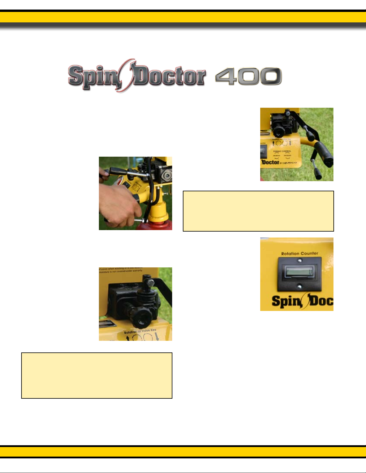
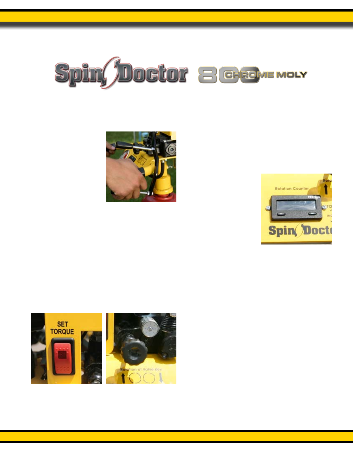
• Slowly operate valve lever to begin opera-
tion in the required direction to open or
close valve.
Situations may vary; it is impossible to list all Hazards.
Stay alert. Be aware. YOU can help or prevent accidents
• Before any operation of Spin Doctor, be
familiar with the locations and functions of
the unit’s instruments and controls. Being
familiar with the machine and its controls
will increase eciency and reduce the pos-
sibility of personal injury or damage to the
unit. The operator should work slowly and
carefully until he or she feels comfortable
with the machine. Speed and skill will be
attained much easier if the necessary time
is spent to familiarize the operator with the
machine and its operations.
• Always check engine oil level and hydrau-
lic oil level in reservoir prior to starting
engine.
• Attach hydraulic boom hoses to the power
pack, making sure they are correctly con-
nected and coupler is locked.
• Remove position lock pins from boom to
allow boom to extend and swivel.
• Start power pac engine. (See engine
owner’s manual for operating instructions)
• Insert extension key attaching to valve nut.
(Valve manufacturers recommend the first
and last turn be done by hand).
• Insert hydraulic motor drive into valve
extension wrench.
AMERICAN WATER WORKS RECOMMENDED VALVE MAIN-
TENANCE PROCEDURES:
Operation and maintenance procedures for various types
of valves are detailed in manufacturer’s operation manuals
and in the appropriate product standards. The following
paragraphs provide the guidelines for most situations.
Basic Valve Exercising
Preparing for your valve exercising activities will require some planning. You will need to assemble maps that will give you
the location of each valve, type of valve and the size of the valve. You will need to know the type of access to the valve so you
come prepared with the right tools to open the access point. If you are working in a street, especially a busy main street, you
will need trac control. Refer to your local and state requirements for trac control.
Operating Instructions
®

www.GETHURCO.com1-800-888-1436
www.GETHURCO.com
Operating Instructions
5
• Utilizing the revolution counter, complete-
ly open (or close) the valve slowing at the
required number of revolutions. DO NOT
OVER-TORQUE VALVE!
• Reverse valve direction to complete ex-
ercise stopping prior to the last complete
turn.
• Remove hydraulic motor drive from key
and complete the last turn of the operation
by hand.
• CAUTION! Opening or closing a valve
too fast can damage the valve or break
the water main.
• Retract boom and insert locking pins for
transport.
WARNING! NEVER MOVE UNIT WITHOUT
FIRST INSERTING LOCKING PINS SECURING
THE BOOM!
Special Note: The Spin Doctor was engineered to be safe
to operate and to meet the torque requirements of most
valve manufactures. The Spin Doctor boom has been tested
at over 2000 ft lbs of torque, and carries a limited life time
warranty against bending caused by torque. Since operating
a valve with excessive torque can be dangerous and damage
the valve, you are encouraged to follow the valve manufac-
tures recommendations. However, if your choice is to “bully”
the valve, we would recommend the use of our Slick Stick
with special penetrating fluid with silicone. This will usually
do the trick. If this does not work and you still want to apply
excessive torque, then the use of an optional impact torque
wrench will increase your odds of success. Hurco offers two
torque wrench options that will give you up to 3000 ft lbs
of torque in short impact bursts. To learn more and to see a
video about dealing with difficult valves, go to our web-
site at www.gethurco.com

www.GETHURCO.com1-800-888-1436
www.GETHURCO.com
Operating Instructions
6
Control Operation of Head Assembly
The Spin Doctor 400 head utilizes very basic functions.
1 Remove travel security pins.
2Lift up on the Latch Handle to release the boom
from the travel position.
3To place the head on the
valve wrench, simply
pull the Spin Doctor
boom towards the valve
wrench, then loosen the
head pivot handle. The
head also pivots side to
side. This will allow the
head to easily drop into
the valve wrench drive
coupler even if the valve
wrench is not perfectly
perpendicular. By feath-
ering the drive control lever, the Spin Doctor
head assembly will drop into the valve wrench
socket.
4 To adjust the torque,
simply turn the torque
control knob clockwise
to increase torque and
counter clockwise to re-
duce torque. The gauge
on the Spin Doctor 400
head reads in ft. lbs of
torque.
5To operate the valve
wrench clockwise, push
down on the drive
control lever, pull up
to operate in a counter
clockwise direction.
6Push the reset button
to zero out the counter
prior to valve exercising.
7When you are done
valve exercising, park
the Spin Doctor in
the park position and
replace all travel security
pins.
Note
Always start with your torque low. As the demand
for torque increases while you are valve exercising,
then increase the torque gradually until the valve
manufacturers torque requirements are met.
Note
You can control the speed of the valve wrench
by slowing the engine speed, feather the drive
control lever or a combination of both.
TM
®
Drive control lever
Torque control knob
Drive control lever
Rotation counter

www.GETHURCO.com1-800-888-1436
www.GETHURCO.com
Operating Instructions
7
Control Operation of Head Assembly
5 To operate the valve wrench clockwise, push
down on the drive control lever, pull up to
operate in a counter clockwise direction. Note,
you can control the speed of the valve wrench
by slowing the engine speed, feather the drive
control lever or turning the Speed Control dial
or a combination of all three. Turning the Speed
Control dial clockwise will slow the wrench
speed and counter clockwise will increase the
wrench speed.
6Push the reset button
to zero out the counter
prior to valve exercising.
7When you are done
valve exercising, park
the Spin Doctor in
the park position and
replace all travel security
pins.
1 Remove travel security pins.
2Lift up on the Latch Handle to release the boom
from the travel position.
3To place the head on the
valve wrench, simply
pull the Spin Doctor
boom towards the valve
wrench, then loosen the
head pivot handle. The
head also pivots side to
side. This will allow the
head to easily drop into
the valve wrench drive
coupler even if the valve
wrench is not perfectly
perpendicular. By feathering the drive control
lever, the Spin Doctor head assembly will drop
into the valve wrench socket.
4To adjust the torque, press the Torque Control
button on the front panel of the Spin Doc-
tor head. The button will illuminate red when
activated. With the engine speed set and the
hydraulics engaged, pull up on the drive con-
trol lever. Now simply turn the torque control
knob clockwise to increase torque or coun-
terclockwise to reduce torque.The torque will
be displayed on the torque gauge. Once the
appropriate torque is reached, release the drive
control lever and turn the Torque Control to off.
The red light will turn off.
TM
®
Drive control lever
Torque control button Torque control knob
Rotation counter

www.GETHURCO.com1-800-888-1436
www.GETHURCO.com
8
Operating Instructions
Control Operation of Head Assembly
1 Remove travel security pins.
2 To place the head on the valve wrench, simply
pull the Spin Doctor boom towards the valve
wrench by releasing both brakes. Push the top
of the brake buttons to deactivate the front and
rear brakes. A red light will illuminate to indi-
cate that the brakes are released. Activate the
boom lift by pushing the top of the Boom Lift
button. A red light will illuminate to indicate
that the boom lift is activated. Pull up on the
drive control lever to raise the boom and push
down to lower the boom. Then loosen the
head pivot handle. The head will pivot forward
and back, and side to side. This will allow the
head to easily drop into the valve wrench even
if the valve wrench is not perfectly perpendicu-
lar. By feathering the drive control lever, the
Spin Doctor head assembly will drop into the
valve wrench socket. Turn off all switches prior
to valve exercising.
3 To adjust the torque, press the Torque Control
button on the front panel of the Spin Doc-
tor head. The button will illuminate red when
activated. With the engine speed set and the
hydraulics engaged, pull up on the drive con-
trol lever. Now simply turn the torque control
knob clockwise to increase torque or coun-
terclockwise to reduce torque. The torque will
be displayed on the torque gauge. Once the
appropriate torque is reached, release the drive
control lever and turn the Torque Control to off.
The red light will turn off.
4 To operate the valve wrench clockwise, push
down on the drive control lever, pull up to
operate in a counter clockwise direction. Note,
you can control the speed of the valve wrench
by slowing the engine speed, feather the drive
control lever or turning the Speed Control dial
or a combination of all three. Turning the Speed
Control dial clockwise will slow the wrench
speed and counter
clockwise will increase
the wrench speed.
5Push the reset button
to zero out the counter
prior to valve exercising.
6When you are done
valve exercising, park
the Spin Doctor in
the park position and
replace all travel security
pins. You will need to
deactivate the brakes and engage the boom lift
in order to park the ERB800 Spin Doctor.
TM
®
Release brakes
Drive control lever
Torque control button
Activate boom
Pivoting head
Torque control knob
Rotation counter

www.GETHURCO.com1-800-888-1436
www.GETHURCO.com 9
Operating Instructions
Dealing with a Problem Valve
Dealing with a problem valve requires a certain amount of
thought and care. The manufacturer of a valve will have a
specific torque requirement for each valve stem. To exceed
that torque amount will most assuredly damage the valve
or valve stem. If you encounter a problem valve that can-
not be opened within the manufacturers torque limit and
you want to try and free the valve, follow this procedure
to improve your chance of success. Note: This procedure is
not a guarantee that you will save every valve. However, by
following these steps you will likely save a good number of
your problem valves.
Step 1
Use the Hurco Slick Stick with special penetrating fluid. You
can find the instructions for the Slick Stick on page 10 of this
manual.
Step 2
If using the Slick Stick did not help to loosen the valve
but you still want to try and free the valve, use an impact
wrench. An impact wrench will apply short-fast bursts of
high torque to help break loose corrosion in the valve and
valve stem. This is the same principal that is used in a tire
shop when they use an impact wrench to remove rusted and
stuck lug nuts. Saving one valve will more than likely pay for
the impact wrench.
Step 3
If Steps 1 and 2 did not loosen the stuck valve, you must
repair or replace the valve. Do not apply excessive torque.
This can be dangerous and should the valve break in the
closed position, it can disrupt your water supply. In a re
emergency or in the event of a critical care customer relying
on this water supply, the consequences could be costly and
life threatening.
Where to purchase a impact wrench.
Hurco can provide you with quality impact torque wrenches
manufactured by Stanley. Call Hurco for pricing and avail-
ability or contact your local Stanley dealer.

www.GETHURCO.com1-800-888-1436
www.GETHURCO.com
10
Operating Instructions
The Slick Stick is used to loosen and lubricate a valve stem on a valve that is stuck. This Slick Stick wand is a panted wand that
will apply lubricant to the valve stem without wasting or spilling the uid. The tip of the Slick Stick is indexed to spray at a 90
degree angle to make lubricating the valve stem easier. You can rotate the position of the tip so it is indexed to the handle
grip. This way you will always know what direction the spray nozzle is spraying.
To use the Slick Stick, rst familiarize yourself with operation and safety precautions.
Safety Precautions
1. The uid used with the slick stick can be dangerous if not used properly. Read all instructions on the uid
container and read the Material Safety Data Sheet (MSDS) provided with the uid. You should keep a copy of
this MSDS sheet with you at all times in case of an emergency. If you do not have a copy of the MSDS sheet,
please contact Hurco immediately or go to our website at www.gethurco.com and download a copy of this
sheet.
2. DO NOT aim Slick Stick at any person or part of the body. Fluids can be dangerous.
3. Check all ttings and nozzles to be sure they are secure and in good operating condition.
4. Use in a well ventilated area.
5. DO NOT use around electrical connections or wires.
Operation
1. Put special penetrating uid into the Slick Stick pressure container. Do not ll container over half. Approxi-
mately one US Gallon.
2. Connect the hose from the pressure container to the Slick Stick with the quick disconnect.
3. Pump the pressure container approximately 10 pumps. Do not over pressurize as this can damage the
plunger. To use the plunger, push down and turn the lever slightly counter clockwise. This should release the
plunger handle. After pressurizing the tank, push the plunder down and turn slightly clockwise to lock.
Note: To relieve the pressure in the tank, carefully and slowly turn the plunger counter clockwise. Wear eye
protection!
4. Lower the Slick Stick to just below the drive nut on the valve.
5. Turn the knob located at the handle end of the wand Counter-clockwise
to release the handle grip.
6. Squeeze the handle grip to apply
a small amount of the special
penetrating fluid.
7. Re-apply if necessary.
8. Operate the valve as described in Basic Valve
Exercising on page 9.
9. Relieve the pressure on the pressure container and store
away.
Maintenance
1. Keep the Slick Stick spray tip and the pressure tank clean and free of dirt.
2. With the exception of replacing the spray tip, the Slick Stick is not eld repairable. If
you are having trouble with your Slick Stick, call Hurco and ask for Service.

www.GETHURCO.com1-800-888-1436
www.GETHURCO.com 11
Troubleshooting
Troubleshooting
PROBLEM:
Power pac won’t start.
SOLUTION:
1. Spin Doctor hoses must be connected to the power pac for the engine to start. Connect hoses from Spin
Doctor to power pac making sure connectors are locked together and start engine.
2. Check battery and connections.
3. Check engine oil.
4. Check fuel.
PROBLEM:
Excessive Hydraulic oil heat build up.
SOLUTION:
1. Check hydraulic oil level in the reservoir. Rell if necessary.
2. Check hydraulic pressure gauge and adjust pressure if necessary.
PROBLEM:
Counter quit working.
SOLUTION:
1. Check wiring for loose or disconnected wire.
2. Check that power is supplied to the head. If the counter doesn’t light power may not be
getting to the counter.
3. Replace counter if required.

www.GETHURCO.com1-800-888-1436
www.GETHURCO.com
12
Maintaining
Maintenance
SPIN DOCTOR:
• Grease pivot point where the Spin Doctor head connects to the boom using grease a gun weekly or as
needed.
• Visually inspect all connections and bolts daily. Physically check bolts and connections weekly.
• Grease all pivot points on ER using a grease gun weekly or as needed.
• Counter is water resistant NOT waterproof. Do not pressure wash, and keep covered when not in use.
• Check all hydraulic hose and tube connections after 8 hours of operation for leaks.
POWER PAC:
• Check engine oil level daily. Rell as needed. Change according to engine manufacturer’s recommenda-
tions.
• Visually check hydraulic tank sight glass level daily. Replenish if necessary.
• At the end of the rst 50 hours of service, replace the in-tank hydraulic uid lter. Thereafter, replace every
500 hours or yearly.
• Follow engine maintenance requirements as noted in manufacturer’s manual provided with your new power
pac.
• Visually inspect all connections and bolts daily. Physically check bolts and connections weekly.
HYDRAULIC FLUID RECOMMENDATIONS
MANUFACTURER UNIVERSAL TRACTOR
FLUID
ARCO .................................................................................ARCO TRACTOR FLUID
AMOCO..........................................................................................1000 Fluid
CHEVRON............................................................................Tractor Hydraulic Fluid
CITGO ...............................................................................................AW/32
MOBIL .......................................................................................Mobiluid 423
SHELL ............................................................................................Donax TD
SUN ............................................................................................... TH Fluid
TEXACO ..........................................................................................THD Fluid
If ‘RED’ Dexron transmission uid is used, replace with same type. Do not mix types of uid.

www.GETHURCO.com1-800-888-1436
www.GETHURCO.com 13
Parts Breakdown & Listing
SD400 Boom Mechanical Parts
ITEM QTY DESCRIPTION PART NO. ITEM QTY DESCRIPTION PART NO.
1 1 HEAD PIVOT BRKT, CM BOOM 2201-011 16 2 SEALED BEARING 2105-214
2 1 HANDLE NUT 990-150 17 1 SWIVEL, SD400, ERG3 2201-202
3 1 PLASTIC SLIDE BLOCK 2201-021 18 1 1/2 STEEL TL/0 HANDLE 2201-232
4 1 CYLINDER ANCHOR ANGLE 2201-022 19 1 HITCH PIN, ERG3 2105-206
5 1 SECONDARY LATCH HANDLE 2201-017 20 1 HITCH MOUNT, ERG3 2105-201
6 1 GAS CYLINDER 225# 2201-222 21 2 SLIDE ROD 2201-020
7 1 PRIMARY LATCH HANDLE 2201-015 22 1 PRIMARY LINKAGE ARM 2201-012
8 1 SPRING PIN 990-101 23 1 SD400 PRIMARY BOOM 2201-003
9 10 BALL STUD (YELLOW) 2201-203Y 24 2 DOG LEG 2201-014
10 10 GAS CYL. SOCKET 2201-201 25 1 SD400 SECONDARY LINKAGE ARM 2201-013
11 10 CYL. SOCKET SPRING 2201-204 26 2 GAS CYLINDER 175# 2201-220
12 2 GAS CYL. 200# 2201-221 27 1 SD400 SECONDARY BOOM ARM 2201-004
13 1 SWIVEL PIN 2101-111 28 1 HEAD SPRING 2101-126
14 1 COTTER KEY 1/8 X 1 1/2 990-119 29 3 SPACER .375 2201-018
15 1 CASTLE NUT 910-117 30 2 SLIDE LINK 2201-016

www.GETHURCO.com1-800-888-1436
www.GETHURCO.com 15
Parts Breakdown & Listing
SD 800 Chrome Moly Boom Mechanical Listing
ITEM QTY DESCRIPTION PART NO. ITEM QTY DESCRIPTION PART NO.
1 1 HEAD PIVOT BRKT, CM BOOM 2301-011 19 1 HITCH MOUNT, ERG3 2105-201
2 2 SLIDE LINK 2201-016 20 1 1/2 STEEL TL/0 HANDLE 2201-232
3 1 HANDLE NUT 990-150 21 1 HITCH PIN, ERG3 2105-206
4 8 CLAMP BODY 2101-122 22 2 WEAR PLATE, SWIVEL 2301-002-25
5 8 CLAMP COVER PLATE 2101-123 23 4 1/8’ DRIVE PIN 990-505
6 1 PLASTIC SLIDE SPACER 2201-023 24 1 SWIVEL, SD800, ERG3 2301-202
7 1 PLASTIC SLIDE BLOCK 2201-021 25 1 PRIMARY LINKAGE ARM 2301-012
8 1 SECONDARY LATCH HANDLE 2301-017 26 1 CM PRIMARY BOOM 2301-003
9 1 PRIMARY LATCH HANDLE 2201-015 27 2 DOG LEG 2201-014
10 1 GAS CYLINDER 225# 2201-222 28 2 PRIMARY BOOM WEAR PLATE 2301-002-25
11 10 BALL STUD (YELLOW) 2201-203Y 29 4 LOCKING GAS CYLINDER 200# 2201-224
12 1 CYLINDER ANCHOR ANGLE 2201-022 30 4 LOCKING CYL. SLEEVE 2201-228
13 2 SLIDE ROD 2201-020 31 4 CABLE RELEASE 2201-225
14 2 GARLOCK BUSHING 2201-052 32 4 HYDRAULIC STEEL TUBE 2101-118
15 1 CASTLE NUT 910-117 33 1 CM SECONDARY LINKAGE ARM 2301-013
16 1 COTTER KEY 1/8 X 1 1/2 990-119 34 1 CM SECONDARY BOOM ARM 2301-004
17 2 SEALED BEARING 2105-214 35 1 HEAD SPRING 2101-126
18 1 RECEIVER HITCH PIN 2110-100 36 3 SPACER .375 2201-018

www.GETHURCO.com1-800-888-1436
www.GETHURCO.com
16
Parts Breakdown & Listing
SD400/800 Chrome Moly Boom
Hydraulics Parts
ITEM QTY DESCRIPTION PART NO.
1 1 MALE FLAT FACE CONNECTOR 2101-120
2 1 FEMALE FLAT FACE CONNECTOR 2101-121
3 2 HOSE 3/8’’ X 74’’ 962-110
4 16 CAPSCREW 1/4 X 1 1/2 NC 901-105
5 8 CLAMP COVER PLATE 2101-123
6 8 TUBE CLAMP BODY 2101-122
7 4 TUBE 2101-118
8 1 HOSE 3/8” X 23” 962-105
9 1 HOSE 3/8” X 21” 962-106
10 1 FITTING 2201-101
11 2 HOSE 3/8” X 31.5” SLEEVED 962-103

www.GETHURCO.com1-800-888-1436
www.GETHURCO.com 17
Parts Breakdown & Listing
ER (Extended Reach) Parts Listing
ITEM QTY DESCRIPTION PART NO. ITEM QTY DESCRIPTION PART NO.
1A 1 SD800 SWIVEL, ERG3 2301-202 11 1 HITCH MOUNT, SD800, VAC250 2250-152
1B 1 SWIVEL SD400 2201-202 12 1 HITCH PIN, ERG3 2105-206
2 8 CLAMP BODY 2101-122 13 1 1/2 STEEL TL/0 HANDLE 2201-232
3 8 CLAMP COVER PLATE 2101-123 14 1 HYD. TUBE, PRIMARY LEFT 2105-212
4 1 PRIMARY ARM, ERG3 2150-202 15 1 HYD. TUBE, PRIMARY RIGHT 2105-213
5 3 CASTLE NUT 910-117 16 2 HOSE 1/2 X 31 1/2’’ MJ-MJ 962-103
6 6 BEARING 2105-214 17 1 HYD. TUBE, SECONDARY, LEFT 2105-210
7 1 HITCH MOUNT, ERG3 2105-201 18 1 HYD. TUBE, SECONDARY, RIGHT 2105-211
8 2 HOSE 1/2 X 40” MJ-MP 962-102 19 1 SECONDARY ARM, ERG3 2105-203
9 1 FEMALE FF COUPLER 961-FEM501-8FP 20 2 HOSE 1/2 X 40” MJ-MJ 962-104
10 1 MALE FF COUPLER 961-FEM502-8FP

www.GETHURCO.com1-800-888-1436
www.GETHURCO.com
Parts Breakdown & Listing
18
SD400 Standard Head Parts Listing
ITEM QTY DESCRIPTION PART NO. ITEM QTY DESCRIPTION PART NO.
1 1 MOTOR BRACKET 2102-005 15 2 VALVE LEVER HANDLE 2102-111
2 1 HYRAULIC MOTOR 2102-113 16 2 HOSE 1/2” X 12” 962-108
3 1 VALVE 2102-110 17 2 RUBBER HANDLE 2101-143
4 1 COUNTER (with harness) 2102-101 18 1 SHIELD BRACE 2102-006-12
5 1 TORQUE GAUGE 2102-155 19 1 COUNTER PROTECTOR 2102-166
6 1 SD400 HEAD SHIELD 2102-006 20 1 COUNTER PICKUP “recracker” 2102-102
7 1 MOTOR DRIVE ADAPTER 2101-006 21 1 MAGNET 2102-173
8 2 FITTING 961-6809-8-8 22 1 PULL BAR 2102-007
9 2 FITTING 961-6801-8-10 23 1 SD400 PIVOT BRACKET 2201-011
10 1 FITTING 961-6801-NOW-8-8 24 1 DRIVE CONTROL LEVER
BRACKET 2102-009
11 1 HOSE 1/4” X 8” 962-130 25 1 SENDING UNIT BRACKET 2102-023
12 1 HOSE 1/2” X 21” 962-106 26 1 PRESSURE CONTROL KNOB 2102-112
13 1 HOSE 1/2” X 23” 962-105 27 1 METAL CABLE CLAMP 1/4 X 1/2 980-010-
25104
14 2 FITTING 961-6400-8-6 28 1 FITTING 4200-108
This manual suits for next models
2
Table of contents
Other Hurco Power Tools manuals
Popular Power Tools manuals by other brands

HEIN-WERNER AUTOMOTIVE
HEIN-WERNER AUTOMOTIVE HW93300 Operating instructions & parts manual

Batavia
Batavia RENOVATION SET operating instructions

Dremel
Dremel 100 Operating/safety instructions

STEINEL
STEINEL HG 2320 E Original operating instructions

YATO
YATO YT-82796 Original instructions

KRAUSMANN
KRAUSMANN 9196 Operation manual

Parkside
Parkside PKGA 20-Li C2 Translation of the original instructions

Apex Tool Group
Apex Tool Group Airetool 2055-R Series OPERATING & SERVICE MANUAL

Zionair
Zionair SK20B Assembly and user instructions

Hazet
Hazet 9020-2 operating instructions

Wacker Neuson
Wacker Neuson BS 70-2 Operator's manual

HIKOKI
HIKOKI CV 350V Handling instructions