Hurricane 3-PT 42 User manual

HURRICANE DITCHER CO., INC. 3-PT 42 DITCHER
SEPTEMBER 2019
Model Number: 3-PT 42 Serial Number: _______________
HURRICANE DITCHER CO., INC.
2425 Cathlinette Rd.
Vincennes, IN 47591
812-886-9663 Fax 812-886-0530
www.hurricane-ditcher.com
E-mail: info@hurricane-ditcher.com

HURRICANE DITCHER CO., INC. 3-PT 42 DITCHER
1
TABLE OF CONTENTS
INTRODUCTION ..................................................................................................................................... 2
SPECIFICATIONS OF THE 3-PT 42 ........................................................................................................ 2
SAFETY PRECAUTIONS ..................................................................................................................... 2-3
WARNING LABELS & ILLUSTRATION ................................................................................................. 3-4
TRANSPORTATION ................................................................................................................................ 5
USING THE 3-PT 42 ............................................................................................................................... 5
CHECKLIST BEFORE OPERATION..................................................................................................... 5-6
OPERATING INSTRUCTIONS ................................................................................................................ 6
UNHITCHING FROM TRACTOR ............................................................................................................. 7
MAINTENANCE ...................................................................................................................................... 7
LUBRICATION ..................................................................................................................................... 7-8
FREE MOVEMENT OF DRIVELINE ........................................................................................................ 8
IDLER ADJUSTMENT ............................................................................................................................. 9
LIMITED WARRANTY ........................................................................................................................... 10
STRUCTURAL COMPONENTS & ILLUSTRATION .......................................................................... 11-12
MECHANICAL COMPONENTS & ILLUSTRATION ......................................................................... 13-14
OPTIONAL COMPONENTS & ILLUSTRATION ................................................................................ 15-16
MAINTENANCE LOG………………………………………………………………………………………………17
NOTES………………………………………………………………………………………………………………18
CAUTION!!!!
• Read the Operator’s Manual.
• Learn to operate this machine SAFELY.
• Be alert. Observe ALL Safety Practices.
• Machines can be hazardous in the hands of
an UNFAMILIAR, UNTRAINED or
COMPLACENT operator.
• Do not risk INJURY or DEATH!

HURRICANE DITCHER CO., INC. 3-PT 42 DITCHER
17
INTRODUCTION
Thank you and congratulations on the purchase of your Hurricane Ditcher 3-PT 42. We certainly
hope that it will be helpful and useful to you. As with all of our ditchers, it has been tested and built with
knowledge, precision, and quality for years of dependable service. As a leader in the ditching industry
since 1984, we continually build on our experience and use customer feedback to maintain and improve
the quality and dependability of our machines.
In order to fulfill a need in agriculture, the 3-PT 42 was developed in 2006 as an efficient and
affordable machine to make surface drainage ditches, to construct and clean waterways and to build and
maintain terraces using a standard farm tractor. Whatever your application, we hope it works well for you.
Please read and follow all safety precautions, operating procedures and maintenance
requirements. Following these recommendations will prevent injury and operation down time. Proper
maintenance and lubrication will prevent machine breakdown and increase its life expectancy, which will
lead to better performance for you.
Please let us know of any comments, suggestions, or problems that may arise.
HURRICANE DITCHER CO., INC. YOUR AUTHORIZED HURRICANE DITCHER DEALER:
2425 Cathlinette Road
Vincennes, IN 47591
812-886-9663
www.hurricane-ditcher.com
info@hurricane-ditcher.com
SPECIFICATIONS OF THE MODEL 3-PT 42
• HP required: 125 to 225 HP on 1000 RPM PTO
• Width of cut: 42 inches at 21 inches deep
• Depth of cut: up to 10 inches in a single pass; up to 27 inches in multiple passes
• Weight of machine: approximately 3,700 pounds with single tail wheel assembly; approximately
4,200 pounds with double tail wheel assembly
• Drive train: 55 series PTO with shear bolts which overload at the tractor end; double 80 roller chain
with idler adjustment
• Certain brands of tractors could require different length PTO and/or hydraulic hoses. Contact your
dealer for detailed specifications.
SAFETY PRECAUTIONS
OBSERVE THIS SYMBOL THROUGHOUT THIS MANUAL. It calls out potential hazards and
dangers. This symbol will be associated with a key SIGNAL WORD that will designate a degree
or level of hazard seriousness. These signal words are as follows:
DANGER! Indicates an imminently hazardous situation that, if not avoided, WILL result in death
or serious injury; a danger that safety guards cannot protect against.
WARNING! Indicates a potentially hazardous situation that, if not avoided, COULD result in
death or serious injury, and includes hazards that are exposed when guards are removed; also
an alert to unsafe practices.

HURRICANE DITCHER CO., INC. 3-PT 42 DITCHER
17
CAUTION! Indicates a potentially hazardous situation that, if not avoided, MAY result in minor or
moderate injury; also an alert to unsafe practices.
INTENDED USE: 3-PT 42 is designed to be pulled by a ROPS- equipped tractor of proper size. It is
not to be used in any other purpose other than its intended use.
BEFORE OPERATION:
• Carefully study and understand this manual. Be sure the operator has read and understands all
operations before using this machine.
• Do not wear loose-fitting clothing which may catch in moving parts.
• Learn to operate this machine safely. Be alert and observe all safety practices. Machines can be
hazardous in the hands of an unfamiliar, untrained or complacent operator. Never risk injury or
death!
• After servicing, be sure all tools and servicing equipment have been removed from the machine.
• Be certain there is no one near the machine before starting.
• Do not stand under or near terracing shield.
• Do not use the ditcher until you are certain that the area in which you are preparing to work is clear.
Be especially watchful for people, animals and moving vehicles that may enter the discharge path.
Remember, soil may be thrown over 60 feet. Rocks and other debris may go farther, so use extreme
caution in any area with buildings or objects that could be damaged from flying debris.
WARNING! Do not operate this machine above 1000 RPM. Excessive speed of PTO can be
dangerous and could cause personal injury or damage to your tractor or ditcher.
WARNING! Do not exceed recommended horsepower (225 HP or less) for this machine.
Excessive horsepower can be dangerous.
• Before each use, inspect the lower shaft behind the impeller wheel for material wrapped around shaft.
Failure to keep shaft clear could result in bearing failure and is not covered under warranty.
DURING OPERATION:
• Keep all shields in place.
• Allow no one to stand on the left side (discharge side) of the machine while it is in operation, whether
it is moving or standing still.
• NO PASSENGERS ALLOWED! Do not allow anyone to ride on ditcher at any time.
• Keep clear of all moving parts.
• Disengage the PTO and shut off tractor engine before servicing, cleaning or clearing a clogged
machine.
• Avoid overhead wires; contact could cause serious injury or death.

HURRICANE DITCHER CO., INC. 3-PT 42 DITCHER
17
WARNING LABELS & ILLUSTRATION
Your 3-PT 42 comes equipped with all safety labels in place. These safety labels are designed to help
you safely operate your equipment. They inform you about possible hazards associated with the normal
operation or foreseeable misuse of the product and how to properly avoid those hazards to prevent
physical injury or death. You are required to read and follow their directions.
1. Keep all safety labels clean and legible.
2. Replace all damaged or missing labels.
3. New equipment installed during repairs may require replacement safety labels to be affixed or
replaced part, if missing, as specified by Hurricane Ditcher Co.
4. Contact your local dealer to order replacement labels.
5. Refer to this section for proper label placement. When installing new labels:
a. Clean placement surface with soapy water or surface cleaning solution and allow to
dry.
b. Peel backing from label, carefully center and place label in proper location ensuring no
creases or air pockets
c. Press label firmly onto the surface and use a straight edge to smooth the label on the
machine for a secure adhesion
Note: Manufacturer will replace decals upon request when worn, damaged or missing.
ITEM
PART #
DESCRIPTION
A1
009040
WARNING – KEEP ALL SHIELDS IN PLACE
B1
009060
WARNING – DANGER OF FALLING DEBRIS
C1
009010
DANGER – STAY CLEAR OF MACHINE WHEN IN OPERATION
D1
009020
DANGER – ROTATING DRIVE LINE

HURRICANE DITCHER CO., INC. 3-PT 42 DITCHER
17
TRANSPORTATION
If you will be transporting your ditcher on a trailer, or on the back of a flatbed truck, make sure the
machine is safely secured. It may cause injury to yourself or others, or damage the machine if not
A1
B1
C1
D1

HURRICANE DITCHER CO., INC. 3-PT 42 DITCHER
17
securely tied down. You may wish to place boards under each parking stand and the ripper tooth to
prevent damage to the floor of your truck or trailer.
USING THE MODEL 3-PT 42
Each customer will use their machine for different purposes and in slightly different ways. We
cannot tell you the proper way to use your machine for your particular purpose, but we can make
recommendations for various uses.
BUILDING OR REWORKING A DRAINAGE DITCH OR WATERWAY – The ditcher throws soil
and debris to the left side. When possible, it is more efficient if the soil is thrown to both sides of the ditch
or waterway. To do this, make your first pass in the center of your ditch or waterway. After turning
around, make your second pass in the opposite direction with the right wheel of your tractor in the cut you
just made. Operate the machine’s impeller wheel 5 to 10 inches deep and travel about 2½ miles per
hour. If the ditch or waterway needs to be deeper, start in the center again and work outward. If the ditch
needs to be deeper but the soil is unable to be thrown out due to the steepness of the ditch bank, take an
additional pass cutting soil off the left bank. This will allow you to make an additional pass traveling in the
same direction cutting soil in the bottom of the ditch and make it easier to discharge the soil. Even if you
have excess horsepower, it is best not to cut over 10 inches deep. Running 5 to 10 inches deep per pass
allows the soil to be broken up sufficiently and dispersed evenly. This same process is used when
cleaning a terrace channel.
RESHAPING OR BUILDING A TERRACE – The terracing shield would be lowered to build up
your terrace when traveling in one direction and raised scattering the soil back up the hill when traveling
the other way. This procedure allows you to increase the water capacity of your terrace without a high
terrace ridge and also allows your good topsoil to be distributed back into the area where it is needed.
This machine can be used to clean small roadside ditches, as well. (Remember, the soil is
thrown out the left side of the machine and may be distributed over a 60 foot area; rocks and other debris
may go farther.) The maximum depth of cut for the 3-PT 42 is approximately 27 inches depending on
how your tractor is set up (primarily tire size).
CHECKLIST BEFORE OPERATION
• Read and understand the operator’s manual.
• Read all information on the safety decals on the machine.
• Check all bolts to make sure they are tight.
• Before connecting to tractor PTO and as general daily maintenance, check for free movement of
driveline and/or slack in chain (See Free Movement of Driveline section on page 11-12).
WARNING! Do not operate this machine above 1000 RPM. Excessive speed of PTO can be
dangerous and could cause personal injury or damage to your tractor or ditcher.
• Check that all hydraulic hoses are secured and will not interfere with the tractor wheels, PTO shaft or
any other part.
• Be sure the PTO is hooked up correctly and will not interfere with the drawbar strap on the tractor.
• Be sure the hitch is secure.
• Check your tractor’s hydraulic oil reservoir level (See Lubrication section on page 10-11).

HURRICANE DITCHER CO., INC. 3-PT 42 DITCHER
17
• Lubricate machine (See Lubrication section on page 10-11).
• Check PTO forward travel. PTO must slide freely and must not bottom out or damage to bearings
and shaft may occur.
• Before running machine each season or once per year, remove the shear bolts and lock nuts from the
PTO shear yoke assembly to verify that the shear yoke is not corroded and will move freely. Reinstall
shear bolts and lock nuts after inspection is complete.
OPERATING INSTRUCTIONS
1) Keep all shields in place.
2) Keep hands, feet and clothing away from all moving parts.
3) Do not allow anyone to ride on this equipment at any time.
4) Learn to operate this machine safely. Be alert and observe all safety practices. Machines can be
hazardous in the hands of an unfamiliar, untrained or complacent operator. Do not risk injury or death!
5) Do not allow anyone to stand on the left side (discharge side) of the machine while it is in operation,
whether it is moving or standing still.
6) Disengage PTO and shut off tractor engine before servicing, cleaning or clearing a clogged
machine.
7) When the machine is in operation, keep in mind that soil, roots, rocks and other debris may be
thrown 60 feet or more out the discharge side causing damage to an object or harm to a person within its
range.
8) Be sure to use rubber straps to secure hydraulic hoses to the tractor to keep them from getting into
the PTO, otherwise damage may occur.
9) Be sure to keep the slip shaft portion (See page 17 item L9) of the PTO shaft well lubricated (See
Lubrication section on page 10-11).
10) Do not engage PTO when tractor is running at high RPM. Slow RPM to idle before engaging PTO.
11) There are two (2) shear bolts in the PTO shaft (See page 17 item L4). If these bolts shear, stop the
tractor, disengage the PTO, shut off the tractor engine, and replace the sheared bolts.
WARNING! Shear bolts are designed to break under a specified load. Do not use a stronger
bolt than is specified by manufacturer!
12) The impeller has two (2) shear bolts (See page 17 item #M2). If a rock or other object is fed into
the impeller, these bolts may shear. When this happens, stop the tractor, disengage the PTO, shut
off the tractor engine, and replace the sheared bolts.
13) In normal conditions, when mud or trash becomes a problem, stop forward travel and allow the
machine to clear itself before moving ahead.
14) When using the terracing shield, adjust the height with the hydraulic cylinder in order to place the
discharged soil where it is needed. NOTE: Remember the terracing shield extends 8 feet beyond
the left side of machine when attached. Use caution near fences, trees or objects on the road.
WARNING! Do not operate this machine above 1000 RPM. Excessive speed of PTO can be
dangerous.
WARNING! Do not exceed recommended horsepower for this machine. Excessive horsepower
can be dangerous. 1000RPM-115-225 HP.

HURRICANE DITCHER CO., INC. 3-PT 42 DITCHER
17
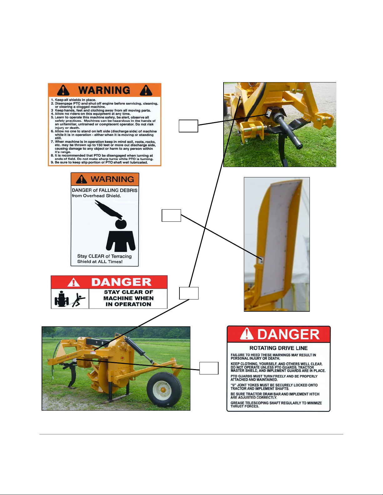
WARNING! Do not use this machine with a PTO adaptor. The Agricultural Driveline
Manufacturers Association and The Association of Equipment Manufacturers discourage the use
of PTO adaptors due to serious safety and operational concerns.
UNHITCHING FROM TRACTOR
1) Park on level ground far enough from obstacles so that the terracing shield may be lowered. Lower
the parking stands to desired height and pin securely. The ripper tooth on the 3Pt42 is designed to
be the front support for the ditcher. Verify that the ripper tooth is intact and shear bolts have not
sheared. Gently lower, the ditcher until it is firmly supported on the ground.
WARNING! Always shut tractor engine off before unhooking PTO.
2) Pull the PTO safety slide lock (See item A below) back on the PTO and remove from tractor spline.
Gently lower PTO onto ripper tooth assembly for storage.
3) If your ditcher is equipped with an optional terracing shield, lower it, release the hydraulic pressure
from the hydraulic lines, and disconnect them from the tractor before pulling forward. If unhitching
you ditcher with the terracing shield attached, additional support may be required to keep ditcher
from tipping over. Do not risk personal injury or damage to ditcher from insufficient support.
4) If using a quick hitch, simply release the pins, lower the quick hitch, and slowly pull forward If not
using a quick hitch, release the clip pins, remove the, hitch pins, and slowly pull forward.
MAINTENANCE
If you are not going to use your machine for a period of time, paint the areas where the soil has
worn off the paint (for example: cutting edge, paddles).
After approximately every ten (10) hours of use, disconnect from tractor and check for the free
movement of driveline and proper chain tension (See page 9).
When the cutting edge wears out, unbolt it, and replace it with a new cutting edge.
When the impeller paddles wear, if slightly worn, weld with a hard surfacing rod on each paddle to
build them back up. NOTE: The factory installed hard surfacing is equal to a 60-65 Rockwell hardness.
If any component of your ditcher appears to be worn and needs replacement, please contact your
dealer for replacement parts.
LUBRICATION
Depending on the tail wheel assembly option chosen, the Model 3-PT 42 has seventeen or eighteen
(17-18) grease fittings. Refer to the Illustration below for the location of these fittings, and read carefully
the information on lubricating those areas. NOTE: Damage may occur due to lack of lubrication.
A – DAILY (before each use) – Grease the following with gun grease: #1-5
1 – The slip joint between PTO halves (remove from tractor, separate halves, apply gun grease
all the way around shaft, and reassemble).
2 – The two (2) universal joints at the ends of each PTO half.
3—The two (2) universal joints at the ends of the drive shaft.
4 – The two (2) fittings on the axle pivot assembly.
5—One (1) or two (2) fittings on tail wheel pivot.
Check Daily
6 – Check your tractor’s hydraulic oil reservoir level. When new, the ditcher’s cylinder will require
approximately ¾ gallon of oil. Use quality hydraulic oil specified by the tractor manufacturer.

HURRICANE DITCHER CO., INC. 3-PT 42 DITCHER
17
B – 24 HOURS OF OPERATION
1 – Check the enclosed gearbox oil level. Fill to the oil level check plug (about 8 inches above
bottom). On backside of gearbox. The factory installed gearbox oil is Lucas ISO 680 industrial
gear oil. Use of this oil is recommended as it is specifically formulated for peak performance of
your Hurricane Ditcher.
C – 40–60 HOURS OR 1–2 WEEKS OF OPERATION – Grease the following with gun grease:
1 – Four (4) flange ball bearings on gearbox – 1 pump each. Slowly apply grease as to not
overgrease and blow out seals.
2 – Two (2) pillow block bearings on drive shaft – 1 pump. Slowly apply grease as to not
overgrease and blow out seals.
D – 100 HOURS OF OPERATION
1 – Remove the inspection plate on the back of the gearbox; check for wear on bearings,
sprockets, chain, and idler; and adjust the idler assembly as required (See Idler Adjustment
section on page 12). Reinstall inspection plate using quality grade silicone sealant under the
inspection plate.
E – YEARLY
1 – Check wheel bearings.
FREE MOVEMENT OF DRIVELINE
When adjusted properly and operating correctly, the driveline should move freely by hand with no
slack in the chain.
CAUTION! Operation of improperly adjusted machine will cause damage to this machine
CAUTION! Operation of improperly adjusting machine will cause damage to this machine and
possibly to your tractor!
FREE MOVEMENT OF DRIVELINE
____________________________________________________________________________________
To check for free movement of driveline and proper tension on chain:
Step 1 – Grasp the front PTO yoke and quickly rock it back and forth. If the PTO moves before the
impeller turns, the chain requires tightening (See Idler Adjustment section below).
Step 2 – If the impeller is difficult to move, check for debris lodged in the machine. Remove any
interfering debris and return to Step 1. If no interferences are found, continue to Step 3.

HURRICANE DITCHER CO., INC. 3-PT 42 DITCHER
17
Step 3– Remove the inspection plate behind both gearboxes and carefully inspect bearings, sprockets,
chain, and idler for damage. If damage is found, repair as needed, reinstall inspection plate using quality
grade silicone sealant under the inspection plate and return to Step 1. If no damage is found, continue to
Step 4.
Step 4 – Release chain tension until impeller wheel and PTO turn freely (See Idler Adjustment below)
IDLER ADJUSTMENT
Remove the inspection plate. Visually inspect the UHMW plastic wear pad for wear or damage.
Replace if needed. The idler adjustment assembly has two (1) bolt and three (3) nuts (See illustration
below). The nuts hold the idler assembly against the chain and act as a jam nut to lock the assembly in
position.
Chain needs MORE tension:
• Loosen Jam Nut C
• Loosen Nut B
• Tighten Nut A to remove any slack and apply slight tension on chain
• Tighten Jam Nut B & C to secure the assembly
Chain needs LESS tension:
Loosen Nut A until desired tension is reached
Tighten Nut B
Tighten Jam Nut C to secure the assembly
Small Gearbox -- Remove the inspection plate on back of the gearbox. Visually inspect the UHMW
plastic wear pad for wear or damage. Replace if needed. The idler adjustment yoke has two (2) nuts
(See illustration below). Nut A holds the idler assembly against the chain and Nut B acts as a jam nut to
lock the assembly in position. Reinstall inspection plate using quality grade silicone sealant under the
inspection plate.
Chain needs MORE tension:
§ Loosen Jam Nut C
§ Loosen Nut B
§ Tighten Nut A to apply tension on
chain
§ Tighten Nut B
§ Tighten Jam Nut C to secure the
assembly
Chain needs LESS tension:
§ Loosen Nut A until desired tension
is reached
§ Tighten Nut B
§ Tighten Jam Nut C to secure the

HURRICANE DITCHER CO., INC. 3-PT 42 DITCHER
17
LIMITED WARRANTY
Hurricane Ditcher Company, Inc. shall be considered the “Company” throughout this warranty
statement.
The Company warrants each new Company product to be free from defects in material and
workmanship. This warranty is applicable only for the normal service life expectancy of the product or
components, not to exceed twelve (12) consecutive months from the date of delivery of the new Company
product to the end user for personal use. This warranty shall not exceed ninety (90) days from the date of
delivery to the end user for commercial use.
Under no circumstances will it cover any merchandise or components thereof, which, in the
opinion of the Company, has been subjected to misuse, unauthorized modifications, alterations, an
accident, or if repairs have been made with parts other than those obtainable through the Company. The
Company in no way warrants tires or other trade accessories since their respective manufacturers
warrant these items separately. The Company’s obligation under this warranty shall be limited to
repairing or replacing free of charge to the original purchaser, any part that, in the Company’s judgment,
shall show evidence of such defect, provided further that such part shall be returned within thirty (30)
days from the date of failure to the Company routed through the dealer and distributor from whom the
purchase was made, transportation charges prepaid.
This warranty shall not be interpreted to render the Company liable for injury or damages of any
kind or nature to person or property. This warranty does not extend to the loss of crops, loss because of
delay in harvesting, or any expense or loss incurred for labor, substitute machinery, rental or for any other
reason.
Except as set forth above, the Company shall have no obligation or liability of any kind on the
account of any of its equipment and shall not be liable for special or consequential damages. The
Company makes no other warranty, expressed or implied, and specifically, the Company disclaims any
implied warranty or merchantability or fitness for a particular purpose. Some states or provinces do not
permit limitations or exclusions of implied warranties or incidental or consequential damages, so the
limitations or exclusions in this warranty may not apply in those areas.
This warranty is subject to any existing conditions of supply, which may directly affect our ability
to obtain materials or manufacture replacement parts. The Company reserves the right to make
improvements in design or changes in specifications at any time, without incurring any obligation to
owners of units previously sold. No one is authorized to alter, modify, or enlarge this warranty. To
enhance warranty, replace decals when worn, damaged or missing.
No warranty will be issued for bearing failure resulting from material wrapping around impeller
shaft.
This warranty is not valid unless registered with Company within 30 days from the date of delivery
to the end user.
HURRICANE DITCHER COMPANY, INC.
2425 Cathlinette Road

HURRICANE DITCHER CO., INC. 3-PT 42 DITCHER
17
Vincennes, IN 47591
812-886-9663
www.hurricane-ditcher.com
info@hurricane-ditcher.com

HURRICANE DITCHER CO., INC. PARTS ILLUSTRATION – MECHANICAL COMPONENTS 3-PT 42 DITCHER
17

HURRICANE DITCHER CO., INC. PARTS LIST - OPTIONAL COMPONENTS 3-PT 42 DITCHER
17
ITEM PART # DESCRIPTION QTY
R004019
TERRACING SHIELD ASSEMBLY (INCL. R1--R7, R13, R15--R17, R23--R24)
R1 002010 HYDRAULIC HOSE - 3/8 X 13'-6" 2 WIRE WITH 1/2NPT MALE END 1
R2 002015 HYDRAULIC HOSE - 3/8 X 14'-6" 2 WIRE WITH 1/2NPT MALE END 1
R3 002133 HAIR PIN 1/8 X 1-1/2 (INCLUDED WITH R6) 2
R4 002132 CYLINDER MOUNTING PIN 1 X 3 (INCLUDED WITH R6) 2
R5 001234 HEX NYLON INSERT LOCK NUT 3/4-10UNC 2
R6 002110 DOUBLE ACTING HYDRAULIC CYLINDER 3-1/2 X 16 1
R7 001080 HEX HEAD CAP SCREW 3/4-10UNC X 3-1/2 GRADE 5 2
004020
SHIELD EXTENSION ASSEMBLY (INCL. R8--R12, R14, R18--R22, R25--R27)
R8 001170 SPLIT LOCK WASHER 3/8 4
R9 001120 HEX NUT 3/8-16UNC GRADE 5 4
R10 004021 SHIELD EXTENSION BRACKET 2
R11 004024 CLEVIS PIN 1/2 X 1-3/4 2
R12 002135 BOWTIE PIN 2
R13 001220 ELEVATOR BUCKET BOLT 1/4-20UNC X 1 14
R14 001005 HEX HEAD CAP SCREW 3/8-16UNC X 1 GRADE 5 4
R15 001110 HEX NUT 1/4-20UNC 14
R16 001715 TERRACING SHIE LD UHMW LINER 1
R17 004018 TERRACING SHIE LD W ELDME NT 1
R18 001025 HEX HEAD CAP SCREW 1/2-13UNC X 1-1/2 GRADE 5 2
R19 004022 SHIELD EXTENSION ADJUSTMENT BAR 2
R20 001716 SHIELD EXTENSION UHMW LINER 1
R21 004016 SHIELD EXTENSION 1
R22 001265 HEX LOCK NUT 1/2-13UNC 2
R23 001165 SPLIT LOCK WASHER 1/4 14
R24 001906 1/2" NPT ISO TIP 2
R25 001110 HEX NUT 1/4-20UNC 12
R26 001165 SPLIT LOCK WASHER 1/4 12
R27 001220 ELEVATOR BUCKET BOLT 1/4-20UNC X 1 12
R28 004014 TERRACING SHIE LD CYLINDER LOCK 1
DOUBLE TAIL WHEEL ASSEMBLY
K1 001691 GREASE SEAL 2
K2
001693 / 001694
INNER BEARING AND RACE 2
K3 001690 HUB ASSEMBLY (ITEMS K1,K2,K4,K8,K10) 2
K4
001686 / 001696
OUTER BEARING AND RACE 2
K5 001692 RETAINING WASHER 2
K6 001689 SLOTTED HEX NUT 7/8-14UNF 2
K7 001688 COTTER KEY 1/8 X 1-1/2 2
K8 001687 DUST CAP 2
K9 001685 WHEEL 8 X 15 - 6 HOLE 2
K10 001697 WHEEL BOLT 7/16-14UNC 12
K11 002260 TIRE 11L15 2
K12 001405 HEX HEAD CAP SCREW 5/8-18UNF X 2 GRADE 8 2
K13 001180 SPLIT LOCK WASHER 5/8 2
K14 004192 RETAINING WASHER 2
K15 003187 UHMW WASHER 2
UPDATED APRIL 2011

HURRICANE DITCHER CO., INC. 3-PT 42 DITCHER
17
OPTIONAL COMPONENTS ILLUSTRATION

HURRICANE DITCHER CO., INC. 3-PT 42 DITCHER
17
MAINTENANCE LOG
DATE
SERVICE PERFORMED
TECHNICIAN

HURRICANE DITCHER CO., INC. 3-PT 42 DITCHER
17
NOTES
_______________________________________________________________________________________________________

HURRICANE DITCHER CO., INC.
2425 Cathlinette Rd.
Vincennes, IN 47591
812-886-9663 Fax 812-886-0530
www.hurricane-ditcher.com
E-mail: info@hurricane-ditcher.com
Table of contents
Other Hurricane Farm Equipment manuals
Popular Farm Equipment manuals by other brands

Z.I.P.P.ER MASCHINEN
Z.I.P.P.ER MASCHINEN ZI-MD500HST user manual

New Leader
New Leader L5034 G4 Assembly/operators/parts manual

HighLine
HighLine Bale Pro CFR650 Operator's manual

Scheppach
Scheppach DP3000 Original instruction manual

GREAT PLAINS
GREAT PLAINS VT1520-0370 Operator's manual

Wacker Neuson
Wacker Neuson GreenTec 1402 Handbook

Brower
Brower CQB20 INSTALLATION INSTRUCTIONS AND REPAIR PARTS LIST

Pottinger
Pottinger FARO 3500 L/D Operator's manual

Degelman
Degelman Pro-till 26 quick start guide

Redexim
Redexim DS800 Operating and parts manual

MacDon
MacDon M155E4 Unloading and assembly instructions

SOLANO HORIZONTE
SOLANO HORIZONTE RT 65 P / E manual