Husqvarna PW 345C Instruction manual

Workshop manual
English
PW 345C, PW 350, PW 360

2 – English
Workshop Manual
PW 345C, PW 350, PW 360
Contents
1 Introduction and safety regulations ............... 3
1.1 General ..........................................................................3
1.2 Revisions........................................................................3
1.3 Target group ...................................................................3
1.4 Safety instructions..........................................................3
1.4.1 General safety instructions ...................................3
1.4.2 Special safety instructions ....................................3
2 Repair instructions........................................... 5
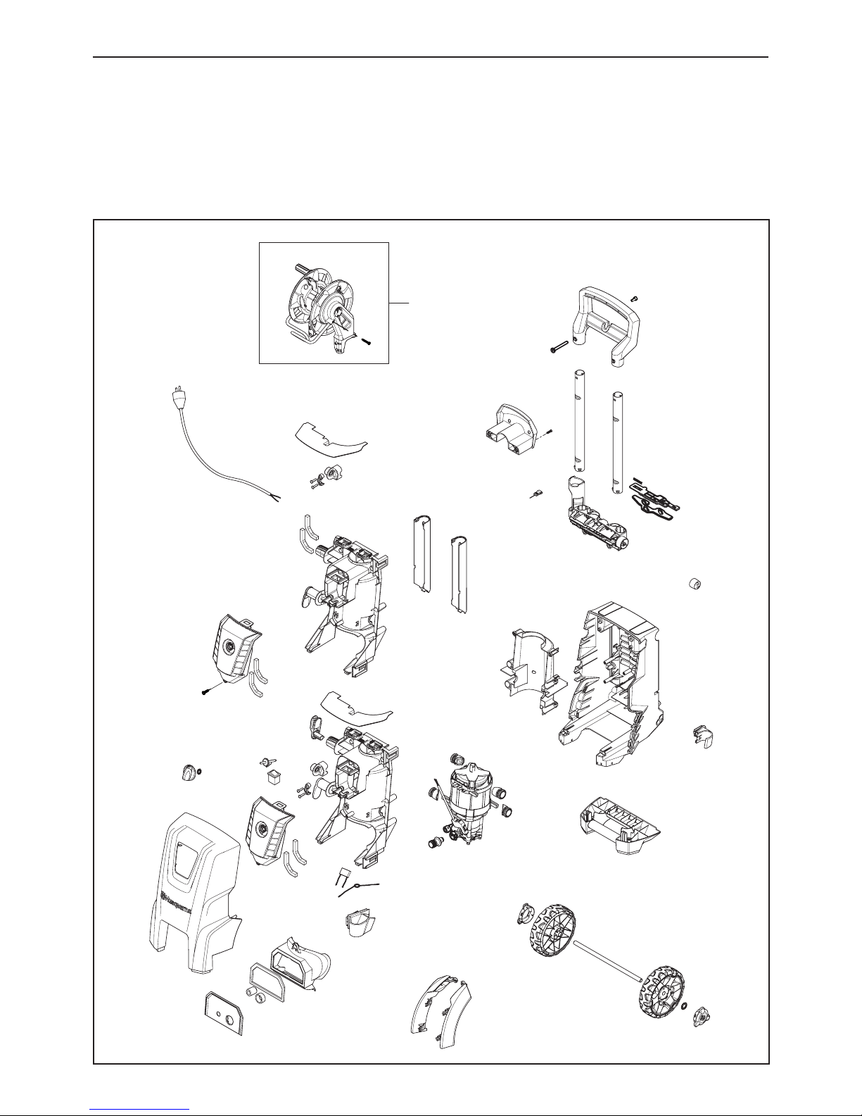
2.1 Product overview............................................................5
2.1.1 Cabinet parts overview, PW 345C,
PW 350, PW360 ...................................................5
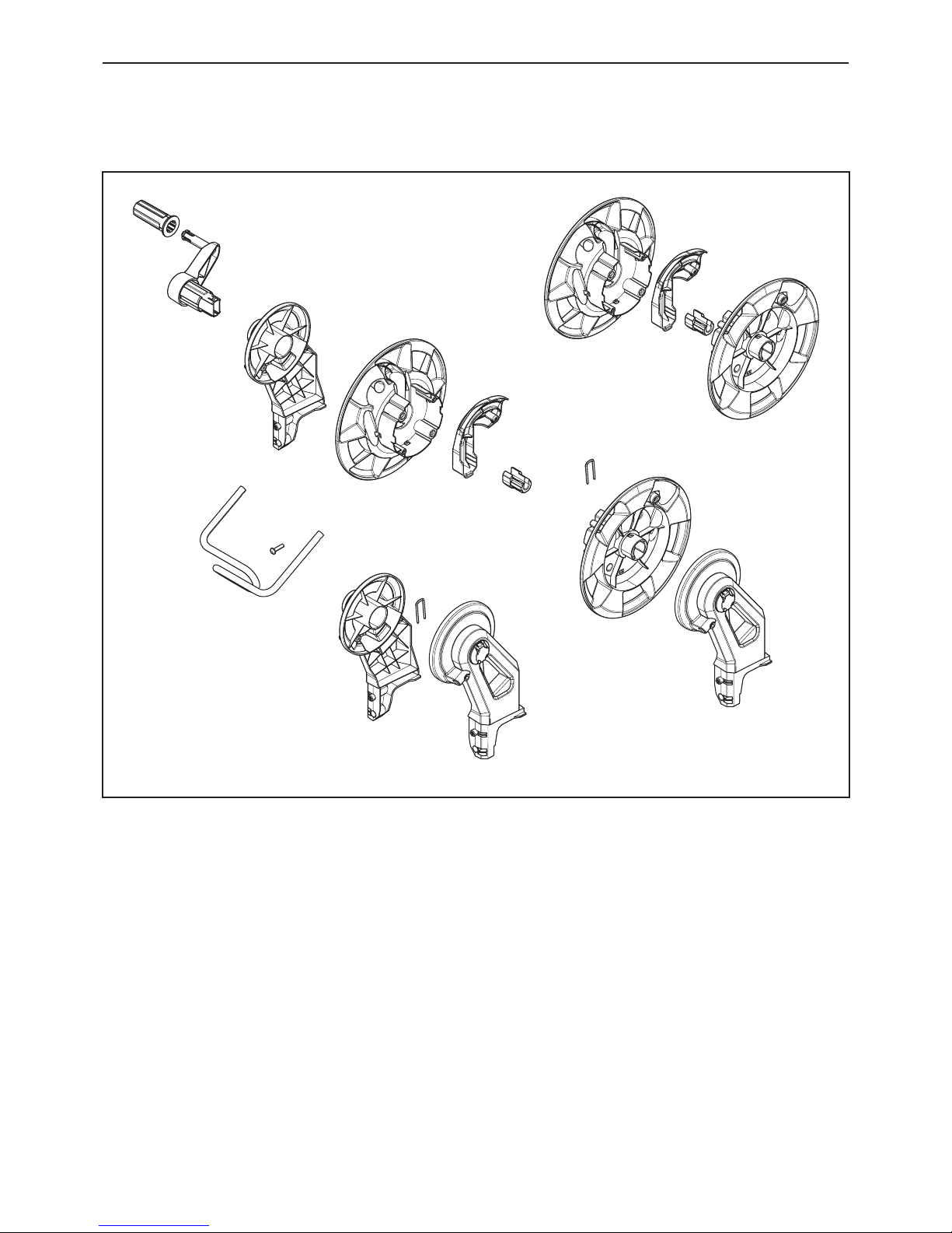
2.1.2 Hose reel overview ...............................................6
2.1.3 Motor/pump unit overview.....................................7
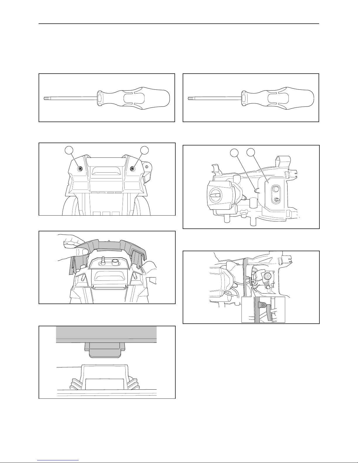
2.2 To disassemble/assemble the front cabinet ...................8
2.3 To disassemble/assemble the pump cover ....................8
2.4 To disassemble/assemble the start/stop system............9
2.5 To disassemble/assemble the switch box cover ............9
2.6 To disassemble/assemble the motor/pump unit,
PW 345C......................................................................10
2.7 To disassemble/assemble the switch ...........................10
2.8 To disassemble/assemble the motor/pump unit,
PW 350, PW 360.........................................................11
2.9 To disassemble/assemble the hose reel/internal
hose PW 350, PW 360.................................................11
2.10 To disassemble/assemble the hose reel,
PW 350, PW 360........................................................12
2.11 To disassemble/assemble the high pressure hose,
PW 350, PW 360........................................................12
2.12 To disassemble/assemble the hose reel,
PW 350, PW 360.......................................................13
2.13 To assemble the hose reel, PW 350, PW 360............13
2.14 To disassemble/assemble the easy start valve ..........14
2.15 To disassemble/assemble
the Non Return Valve (NRV) ......................................14
2.16 To disassembly/assemble the pump ..........................15
2.17 To measure the resistance of the electrical motor......16
3 Specications ................................................. 17
3.1 Technical data .............................................................17
4 Appendices and schedules ........................... 18
4.1 Operating supplies .......................................................18
4.1.1 Recommended oil types .....................................18
4.1.2 Recommended lubrication ..................................18
4.1.3 Recommended glue............................................18
4.1.4 Tools ...................................................................18
4.2 Motor pump function
<Machine stopped and hose emptied>, PW 345C only.....19
4.3 Motor pump function
<Machine operation>, PW 345C only ................................19
4.4 Motor pump function
<Machine standby>, PW 345C only...................................20
4.5 Motor pump function <Machine stopped and
hose emptied>, PW 350,PW 360 only .........................20
4.6 Motor pump function
<Machine operation>, PW 350, PW 360 only ....................21
4.7 Motor pump function
<Machine standby>, PW 350, PW 360 only.......................21
4.8 Wiring diagram, PW 345C ...........................................22
4.9 Circuit diagram , PW 345C...........................................23
4.10 Wiring diagram, PW 345C..........................................24
4.11 Circuit diagram, PW 345C..........................................25
4.12 Wiring diagram, PW 350, PW 360 .............................26
4.13 Circuit diagram, PW 350, PW 360 .............................27

English – 3
1 Introduction and safety regulations
1.1 General
This workshop manual gives a full description of how to
do troubleshooting, repair and test of the high pressure
washer. It also gives safety instructions that the
personnel must obey during repair work.
1.2 Revisions
If there are changes to the product, these are gradually
introduced into ongoing production. These changes can
have an effect on servicing and/or spare parts. This can
cause sections of the workshop manual to become out of
date. Servicing information is sent out for each change.
To make sure that the repair and servicing instructions
are complete and up to date, always read the workshop
manual together with all servicing information applicable
for the high pressure washer.
1.3 Target group
This workshop manual is written for personnel with a
general knowledge of how to repair and do servicing on
high pressure washers.
All personnel that repair or do servicing on the high
pressure washer must read and understand the
workshop manual.
1.4 Safety instructions
WARNING: All personnel that repair or do
servicing on the high pressure washer
must read and understand the safety
instructions.
1.4.1 General safety instructions
The service center that repairs the high pressure washer
must have safety devices that comply with local
regulations.
Warnings and cautions are used to point out specially
important parts of the workshop manual.
WARNING: Used if there is a risk of injury
or death if the instructions are not followed.
CAUTION: Used if there is a risk of material
damage if the instructions are not followed.
1.4.2 Special safety instructions
WARNING: Inhalation of aerosols can be
hazardous to health. Where applicable use
a device in order to avoid or reduce aero-
sols production, e.g., a shield covering the
nozzle. For protection against aerosols use
a respiratory mask of class FFP 2 or higher.
WARNING: Always unplug the power plug
before cleaning or maintenance and when
replacing parts or converting the machine
to another function.
WARNING: Observe the national safety
regulations issued, for example, by the
employers liability insurance association,
social security institutions, occupational
safety and health authorities or other
organizations.
WARNING: Hold the spray lance rmly with
both hands. The spray lance is affected by
a thrust of up to 16,4N during operation.
WARNING: The operator and anyone in the
immediate vicinity of the site of cleaning
should take action to protect themselves
from being struck by debris dislodged
during operation. Wear goggles dur-ing
operation.s.
WARNING: Disconnect from electrical
power supply before carrying out user
maintenance.
WARNING: To ensure the appliance safety
only use original spare parts from the
manufacturer or approved by the manufac-
turer.
WARNING: High pressure hoses, ttings
and couplings are important for the safety
of the appliance. Only use hoses, ttings
and couplings recommended by the manu
facturer.
WARNING: Do not use the appliance if a
supply cord or important parts of appliance
are damaged, e.g. safety device, high
pressure hose and trigger gun.
WARNING: The appliance is only intended
for cleaning outdoors.
Introduction and safety regulations

4 – English
WARNING: Appropriate ear protection must
be used.
WARNING: Never use the machine in an
environment where there could be a danger
of explosion. If any doubt arises, contact
the local authorities.
WARNING: It is not allowed to clean asbes-
tos containing surfaces with high pressure.
WARNING: This high pressure washer must
not be used at temperatures below 0°C.
WARNING: Voltage and frequency of the
machine (see rating plate) must match the
voltage of and fre-quency of the mains
supply.
WARNING: Only connect the machine to
electrical installation made by a certied
electrician and comply with IEC 60364-1.
WARNING: It is recommended that the
electrical supply to the machine should
include a residual current device that will
interrupt the supply if the leakage current
to earth exceeds 30 mA for 30 ms.
Introduction and safety regulations

English – 5
2 Repair instructions
Repair instructions
2.1 Product overview
2.1.1 Cabinet parts overview, PW 345C, PW 350, PW360
Max. Torque for plastic screws: 2,0 Nm
PW 350
PW 360

6 – English
2.1.2 Hose reel overview
Repair instructions

English – 7
2.1.3 Motor/pump unit overview
4 Nm
Loctite 245
4 Nm
Loctite 245
16 Nm
16 Nm
16 Nm
Repair instructions

8 – English
2.2 To disassemble/assemble the
front cabinet
1. Tools: Torx 20 screwdriver.
2. Remove the 2 torx TX20 screws (A) from the bottom.
Then remove the feet.
3.
A
A
Remove the cover by hand.
4. Assembly: Make sure that the 2 hooks in the top of the
cabinet are in the correct position.
2.3 To disassemble/assemble the
pump cover
1. Tools: Torx 20 screwdriver.
2. Remove 1 torx TX20 screw (A).
3. Remove the motor/pump unit oating cover (B).
4.
AB
Assembly: Make sure that the foam and the air barrier
are installed correctly.
Repair instructions

English – 9
2.4 To disassemble/assemble the
start/stop system
1. Remove the micro switch box by hand. Now you have
free access to the start/stop valve.
2. Remove the start/stop valve with a 25 mm spanner.
3. Assembly: Check that all parts are correctly
assembled, see gure below. Install the start/stop valve.
2.5 To disassemble/assemble the
switch box cover
1. Tools: Torx 20 screwdriver.
2. Remove 1 torx TX20 screw (A).
3. Note how the wires are installed. Remember to install
the foam (B) during assembly.
A
B
Repair instructions

10 – English
2.6 To disassemble/assemble the
motor/pump unit, PW 345C
1. Remove all wires from the motor. The wires can
remain on the switch.
2. Remove 8 torx TX20 screws. The structural front can
now be removed without dismounting the capacitor and
power cable.
2.7 To disassemble/assemble the
switch
1. Remove all wires from the switch.
2. Note that the 1/ON position of the switch is placed
over the “1” marking inside the switch box.
Repair instructions

English – 11
2.8 . To disassemble/assemble the
motor/pump unit, PW 350, PW 360
1. Disassemble parts until there is free access to the
motor/pump unit.
2. Remove the internal hose from the pump by removing
the U-pin. Make sure that you do not loose the spring
and the Non Return Valve (NRV) from the water outlet!
2.9 To disassemble/assemble the
hose reel/internal hose PW 350,
PW 360
1. Remove 1 torx TX20 screw to remove the motor/pump
unit back cover.
2. Now you have access to the internal hose.
Repair instructions

12 – English
2.10 To disassemble/assemble the
hose reel, PW 350, PW 360
1. Remove 4 torx TX20 screws to remove the telescopic
handle.
2. Remove 2 torx TX20 screws from the rear side.
3. Remove the hose reel from the cabinet.
2.11 To disassemble/assemble the
high pressure hose, PW 350, PW 360
1. Remove the torx TX20 screw and the u-pin.
2. Remove the hose router.
Repair instructions

English – 13
2.12 To disassemble/assemble the
hose reel, PW 350, PW 360
1. Remove the hose from the internal hose.
Remove the 2 torx TX20 screw (1 on each side) from the
aluminium hose guide.
Note: The length of the 2 screws are longer than all other
screws.
2.13 To assemble the hose reel,
PW 350, PW 360
1. Make sure that the hose nipple is correctly greased
before assembly.
2. Install the hose into the hose reel. Connect to the
brass part from the internal hose.
3. Install the hose reel holder. Make sure to install the
lock clamp correctly. It MUST be installed through both
the plastic hose reel holder AND the brass parts.
Repair instructions

14 – English
2.14 To disassemble/assemble the
easy start valve
1. Put the pump on a table.
2. Disassemble the easy start valve.
3. Assemble in the following order:
- 1. O-ring.
- 2. Easy start insert.
- 3. Spring.
- 4. Ball.
- 5. Ball guide.
- 6. Plug.
31 2 4 56
2.15 To disassemble/assemble the
Non Return Valve (NRV)
1. The NRV is placed behind the water outlet.
2. First install the NRV, then the spring.
Note: Make sure that the spring is placed correctly
before you install it in the water outlet.
.
Repair instructions

English – 15
2.16 To disassembly/assemble the
pump
1. The bearing system can only be installed in one
direction. The ball ring can be installed in both directions.
Oil level: 60 ml.
2. The gure below shows the pump after opening the
cylinder head from the cylinder block.
Note: The pressure valves must be placed correctly!
3. In the bottom of the hole for the suction valve there is
a guidance (rotation lock). The legs of the suction valves
MUST be placed on each side of this guidance!
4. Before assembly of the pump:
- Make sure that the suction valves are installed
correctly.
- Verify the level of the valves. One O-ring must be
completely under the surface.

16 – English
2.17 To measure the resistance of the
electrical motor
On a 2.1 kW Motor:
1. 7.0 Ω +-10%
2. 8.8 Ω +-10%
3. 1.74 Ω +-10%.
3
1
2
Earth wire
Capacitor plug
Power supply plug

English – 17
3 Specications
3.1 Technical data
Value Unit PW 345C PW 350 PW 3601PW 3602
Max pressure bar 145 150 160 160
Voltage V 230 230 230 230-240
Frequency Hz 50 50 50 50
Rated current A 10 9.5 10 9.6
Power consumption kW 2.4 2.1 2.3 2.3
Motor speed min-1 17.500-18.000 2800 2800 2800
Flow rate, HP l/min 7 7 6.8 7
Pump pressure bar 122 ±9 122 ±9 160 160
Nozzle pressure bar 115 ±9 115 ±9 115 ±9 115 ±9
Standby pressure bar 15-35 15-35 15-35 15-35
Retaining time min 5 5 5 5
Oil contents ml 60 80 80 80
Oil type - LHM32 LHM32 LHM32 LHM32
Max water inlet temperature °C 40 40 40 40
Max water inlet pressure bar 10 10 10 10
High pressure hose length m 8-10m 9-10 9-10 9-10
Suction height m 1 1 1 1
Electric cable m 5 5 5 5
Insulation class - F F F F
Tightness - IPX5 IPX5 IPX5 IPX5
1 = 230V / 50Hz
2 = 230-240V / 50Hz
Specications

18 – English
4 Appendices and schedules
4.1 Operating supplies
4.1.1 Recommended oil types
The pump is lled with 60 ml LHM 32 from the
production.
In case of service where the oil must be changed,
Husqvarna recommends to use 60 ml Bartram HV 46.
Alternative oil types that are allowed:
• BP, Bartram HV 46
• Shell, Tellus T 46
• Exxon, Statoil Univis N 46
• Mobil Oil Mobil DTE 25.
4.1.2 Recommended lubrication
White grease for o-rings, sealing etc.:
• Silicone grease,
Unisilkon L250 for all moveable parts and O-rings
• Gardena
• Silicone grease,
DOW CORNING(R) M 55 O-RING LUBRICANT for
all stationary O-rings.
4.1.3 Recommended glue
• Loctite 245, alternatively Loctite 243 (to lock the
4 pcs aluminum plugs in the pump).
4.1.4 Tools
Appendices and schedules
1 2 3 4
Item Description Used for Article number
1Screw driver, Flat For lock clamps N/A
2T-handle Torx T20 For screws with torx head 588 59 85-01
3T-handle Allen key, 5 mm For screws with hexagonal socked head 502 50 64-01
3T-handle Allen key, 6 mm For screws with hexagonal socked head 504 90 00-01
4 Spanner For pump bolts and nuts N/A

English – 19
4.2 Motor pump function
<Machine stopped and hose emptied>, PW 345C only
4.3
Breaker/Micro switch is inactivated
as no force is applied to the button
from the pressure in the hose and
the motor is ready to start
SS piston is clossing
towards pressure side
Gun trigger is unactivated
The whole system is with
out pressure and water
NRV is closed no pressure and
no flow pump
Easy start valve is in it’s closed
position. Ball pressed against
pressure side to secure suction
ability
Motor pump is stopped
Ready to start
Motor pump function
<Machine operation>, PW 345C only
SS piston is clossing
towards pressure side Gun trigger activated
NRV is open by pressure and
flow from pump
Easy start valve is in it’s
operation position. Ball pressed
against inlet.
Motor pump is running
Breaker/Micro switch is inactivated
as no force is applied to the button
from the pressure in the hose and
the motor is ready to start
Appendices and schedules

20 – English
4.4 Motor pump function
<Machine standby>, PW 345C only
SS piston is clossing
towards the 12 mm O-ring and
securing standby pressure
Gun trigger is unactivated
NRV is closing by decreased
pressure and flow from pump
Easy start valve is in it’s closed
position. Ball pressed against
pressure side to secure suction
ability
Motor pump is stopped
Breaker/Micro switch is activated
as is applied to the button from the
pressure in the hose and
the motor is not running
4.5 Motor pump function
<Machine stopped and hose emptied>, PW 350, PW 360 only
SS piston is clossing
towards pressure side
Gun trigger is unactivated
the whole system is with
out pressure and water
NRV is closed no pressure and
no from pump
Easy start valve is in it’s closed
position. Ball pressed against
pressure side to secure suction
ability
Motor pump is stopped
ready to start
Breaker/Micro switch is inactivated
as no force is applied to the button
from the pressure in the hose and
the motor is ready to start
Appendices and schedules
This manual suits for next models
2
Table of contents
Other Husqvarna Pressure Washer manuals

Husqvarna
Husqvarna PW 130 User manual

Husqvarna
Husqvarna 5525PW User manual

Husqvarna
Husqvarna 1906 User manual

Husqvarna
Husqvarna pw3100 Setup guide

Husqvarna
Husqvarna Pressure Washer User manual

Husqvarna
Husqvarna PW 235 Instruction manual

Husqvarna
Husqvarna PW 125 Instruction manual

Husqvarna
Husqvarna 1337PW User manual

Husqvarna
Husqvarna PW 125 User manual

Husqvarna
Husqvarna PW 240 User manual