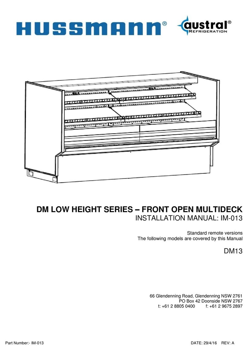
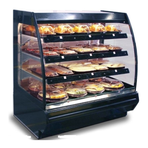
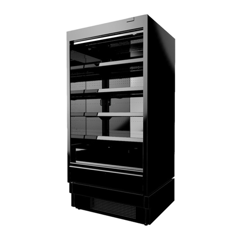
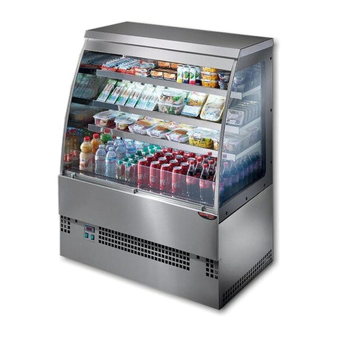
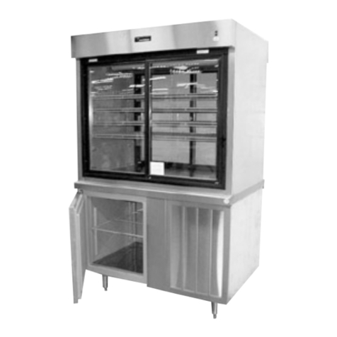
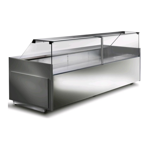
Hussmann Q3-DV Original operating instructions

Q3-DV
DELI SERVICE CASE, VERTICAL GLASS
INSTALLATION & OPERATION GUIDE
/CHINO
Q3-DV
DELI SERVICE CASE, VERTICAL GLASS REV. 1217
Installation
& Operation
Manual

2
This Booklet Contains Information on:
Q3-DV refrigerated, bakery service merchandiser.
Shipping Damage
All equipment should be thoroughly examined for shipping
damage before and during unloading.
This equipment has been carefully inspected at our factory
and the carrier has assumed responsibility for safe arrival.
If damaged, either apparent or concealed, claim must be
made to the carrier.
Apparent Loss or Damage
If there is an obvious loss or damage, it must be noted on
the freight bill or express receipt and signed by the carrier’s
agent; otherwise, carrier may refuse claim. The carrier will
supply necessary claim forms.
Concealed Loss or Damage
When loss or damage is not apparent until after equipment
is uncrated, a claim for concealed damage is made. Make
request in writing to carrier for inspection within 15 days,
and retain all packaging. The carrier will supply inspection
report and required claim forms.
Shortages
Check your shipment for any possible shortages of
material. If a shortage should exist and is found to be the
responsibility of Hussmann Chino, notify Hussmann Chino.
If such a shortage involves the carrier, notify the carrier
immediately, and request an inspection. Hussmann Chino
will acknowledge shortages within ten days from receipt
of equipment.
Hussmann Chino Product Control
The serial number and shipping date of all equipment
has been recorded in Hussmann’s !les for warranty and
replacement part purposes. All correspondence pertaining
to warranty or parts ordering must include the serial number
of each piece of equipment involved, in order to provide
the customer with the correct parts.
/CHINO
A publication of HUSSMANN®Chino
13770 Ramona Avenue • Chino, California 91710
(909) 628-8942 FAX
(909) 590-4910
(800) 395-9229
Keep this booklet with the case at all times for future
reference.
General Instructions
Table of Contents
General Instructions.....................................................2
Shipping Damage ...................................................................... 2
Apparent Loss or Damage..........................................................2
Concealed Loss or Damage ...................................................... 2
Shortages .................................................................................. 2
Hussmann Chino Product Control ............................................. 2
Leveling Labels.............................................................3
Installation.....................................................................4
Leveling ..................................................................................... 4
Leg Adjustments ........................................................................ 5
Arm Adjustments........................................................................ 6
Glass Adjustments ..................................................................... 7
Cut and Plan Views...................................................................11
Location ................................................................................... 11
Uncrating the stand...................................................................11
Case Line Up/Joining.................................................13
Bumper Installation.....................................................14
Plumbing......................................................................17
Refrigeration................................................................17
Refrigerant Type ...................................................................... 17
Piping....................................................................................... 17
Refrigeration Lines................................................................... 17
Control Settings ....................................................................... 17
Access to TEV Valves and Drain Lines ................................... 17
Electronic Expansion Valve (Optional)..................................... 17
Specifications Sheet...................................................18
Electrical......................................................................19
Wiring Color Code ................................................................... 19
Electrical Circuit Identi!cation.................................................. 19
Electrical Service Receptacles (When Applicable) .................. 19
Field Wiring and Serial Plate Amperage .................................. 19
Ballast Location ....................................................................... 19
Ashrae Color Code .................................................................. 19
Finishing Touches.......................................................20
Bumper Installation Tips .......................................................... 20
Installing Splash guard ............................................................ 20
User Information.........................................................20
Stocking................................................................................... 20
Important Steps ....................................................................... 20
Case Cleaning ......................................................................... 20
Cleaning Glass and Mirrors ..................................................... 20
Non-Glare Glass ...................................................................... 21
Plexiglass and Acrylic Care ..................................................... 21
Cleaning................................................................................... 21
Antistatic Coatings ................................................................... 21
Maintenance................................................................22
Electrical Wiring Diagrams........................................23
Wiring Diagrams .........................................................24
Troubleshooting .........................................................32

This equipment is to be installed
to comply with the applicable
NEC, Federal, State , and Local
Plumbing and Construction
Code ha ving jurisdiction.
ATTENTION
INSTALLER

3
Cut and Plan Views
Installation
Location
The refrigerated merchandisers have been designed
for use only in air conditioned stores where temperature
and humidity are maintained at or below 75°F and 55%
relative humidity. DO NOT allow air conditioning, electric
fans, ovens, open doors or windows (etc.) to create air
currents around the merchandiser, as this will impair its
correct operation.
Product temperature should always be maintained at a
constant and proper temperature. This means that from the
time the product is received, through storage, preparation
and display, the temperature of the product must be
controlled to maximize life of the product.
Uncrating the Stand
Place the !xture as close to its permanent position as
possible. Keep in place, attached case until ready to set/bolt
to adjoining case.
Exterior Loading
These models have not been structurally designed to
support external loading. Do not walk on their tops;
This could cause serious personal injury and damage to
the !xture.
Setting and Joining
The sectional construction of these models enable them
to be joined in line to give the effect of one continuous
display.
An Alignment pin kit is supplied with every case and must
be used in alignment.
Q3-DV
22.5° Outside We dge
41 3/8"
31 1/16"
DRAIN
RE F. DROP
47 1/4"
9"
ELEC T.
Q3-DV
22.5° Inside Wedge
DRAIN
38 7/8 "
41 3/8"
REF.
DROP
22 3/4"
9"
ELECT.
Q3-DV
45° Inside We dge
41 3/8"
53 3/8"
21 3/4"
12"
ELEC T.
Drain
RE F. DROP
Q3-DV
45° Outside Wedge
ELEC T.
6 3/4"
41 3/8"
38 7/16"
Drain
41 3/8"
22"
8"
6 1/8"
5"
Elect
Drain Refrig
Q3-DV Plan View
Straight Section
25 1/8"
48" ( Variable Lengths)
50 1/4" ( Variable Lengths)
1 1/8"
End
Panels
1 1/8"
End
Panels
C
L
24 7/8"
27"
12"
14"
15 3/8"
23 3/8"
28"
52 1/8"
27 1/2"
5 3/4"
25 3/8"
10 1/4"
42 1/4"
14 3/4"
23"
15 3/4"
24 3/8"
7 1/4"
5 7/8"
8"

4
WARNING
1. DO NOT load or stand over top of case. Glass breakage may occur if precautions
are disregarded.
*
Broken glass can cause lacerations, cuts, and puncture wounds which may
result in severed arteries or tendons, amputations, eye injuries, or exposure to
disease.
Notice

5
Unloading
NOTICE
Do NOT remove Foam Blocks from shelves
and glass until the merchandisers are
positioned for installation. Shelves or
merchandising glass may be damaged.
Loose
Items
Warning
Labels
Foam Blocks
in place
Boards
fastened
Case is to arrive at store as was shipped form fac-
tory. See reference above for proper shipment refer-
encing. (Not actual case)
Receiving Case
Upon receiving your new Hussmann Case all equip-
ment should be thoroughly examined for shipping
damage before and during unloading. This equipment
has been carefully inspected at our factory. Any claim
for loss or damage must be made to the carrier. The
carrier will provide any necessary inspection reports
or claim form.
If there is obvious loss or damage, it must be noted
on the freight bill or express receipt and signed by the
carrier’s agent; otherwise carrier may refuse claim.

6
Q3-DV Lifting and Transport
Instructions
1. The Q3-DV can be lifted by a forklift at typical lift-
ing points.
2. Ensure lower body panels are removed before
lifting with a forklift. Serious damage will occur if
the body panels are not removed. (Shipped loose
from factory)
3. Make sure that fork spacing and width will not
damage drain or come in contact with piping, or
electrical lines
4. Be sure that the forks are long enough to sup-
port beyond the center of the case but not dam-
age near components. Check for proper balance
before moving. A minimum fork length of 36” is
recommended for 68” wide cases
Installation (cont’d)
5. The Q3-DV merchandiser can be raised at one
end underneath the deck with a forklift or J-Bar if
forklift is not accesible to allow the placement of
rollers or dollies.
6. Evenly support the entire base structure on rollers
or dollies before attempting to move. Each Base
Leg must have its own dollie to properly support
the case.
WARNING
Improper placement of forks may damage
drainage piping. Use a spotter when placing
forks. Make sure that piping will not be dam-
aged. Use J-Bars or Jacks if forks cannot be
used safely
Lifting Points are typical and dependent upon size of
case and refrigeration application, drainage configu-
rations will call for altercations in Lifting Zones.
Below are the following drainage configurations and
lifting should be altered to the expected model.
Drain
Q3-DV Drain Location

7
Skid Removal
Important: See lifting instructions to properly lift case
when being placed on dollies or permanent location.
(See page 6 for Lifting Instructions.)
Lifting Points
Leave all hardware and fittings in place until case is
located at or near its preferred location. Using forklift
or J-Bar lift the case from the skid and placing dollies
underneath each base leg, proceed to moving the
case to its designated location if not done so already.
Dollie Placement
The Illustration below demonstrates perfect place-
ment of a dollie per 1 side for both base legs of the
merchandiser.
Move the fixture as close as possible to its perma-
Installation (cont’d)
nent location and then remove all packaging and
prepare to remove off Skid. Remove all separately
packed accessories such as kits, and panels. Check
for damage before discarding packaging.
Hardware Removal
Remove screws as well as fastened plates bolted to
skid at each base leg.
Remove fastened plates only upper base legs are to
remain fastened onto case.
Once the fastened plates are removed a J-Bar can
be used to lift at each end of the leg bases to remove
the below skid

8
Installation (cont’d)
Level Case
Position the case at the highest point. Set a long
magnetized level (4ft [1220 mm] or more) on
either underneath the deck or on top of the case.
Ensure to level case from front to back and side
to side.
Level
(4 ft[1220mm])
Level Adjustment
Use shims at each corner of the case to level
out any discrepancies in order to optimize case
performance and proper drainage.
Note: To avoid removing concrete flooring, begin
line up levelling from the highest point of the
store floor.
Level
(4 ft[1220mm])

9
Installation (cont’d)
Setting and Joining
The sectional construction of these models enable
them to be joined in line to give the effect of one con-
tinuous display.
An alignment pin kit is supplied with every case and
must be used in alignment.
Leveling
IMPORTANT! IT IS IMPERATIVE THAT CASES
BE LEVELED FROM FRONT TO BACK AND
SIDE TO SIDE PRIOR TO JOINING. A LEVEL
CASE IS NECESSARY TO INSURE PROPER
OPERATION, WATER DRAINAGE, GLASS
ALIGNMENT AND OPERATION OF THE HING-
ES SUPPORTING THE GLASS. LEVELING
THE CASE CORRECTLY WILL SOLVE MOST
HINGE OPERATION PROBLEMS.
ALIGNMENT PIN
ALIGNMENT TAB
CASE BOLTING
LOCATION
Snapping Chalk Lines
Prepare permanent positioning by marking floors
with Chalk snap lines where cases are to be located.
Chalk lines are to run along the base or legs of
cases.

10
Installation (cont’d)
Setting
STEP 1. Using case blueprints, measure off and
mark on the floor the exact dimensions of where
the cases will sit. Snap chalk line for front and
back positions of base rail or pedestal. Mark the
location of each joint front and back. Find the
highest point throughout the lineup. FLOORS
ARE NORMALLY NOT LEVEL! Determine the
highest point of the floor; cases will be set off
this point. All cases in the entire lineup must be
brought up to the highest level of the case sitting
at the highest point in the lineup.
1’
Do not use bolts to pull cases together.
It is the contractor’s responsibility to install
case(s) according to local construction and
health codes.
ATTENTION
INSTALLER
STEP 2. Set first case over the highest part of
the floor and adjust legs so that case is level.
STEP 3. Set second case within one foot (1’) of
the first case. Keep the supports along the length
of the case and far end of case. Level case to
the first using the instructions in step one.

11
STEP 4. Apply liberal bead of case joint sealant
(Silicone) to first case. Sealant area is shown in
illustration. Apply heavy amount to cover entire
shaded area. (pg10)
STEP 5. Slide second case up to first case
snugly. Then level second case to the first case
so glass front, bumper and top are flush.
Installation (cont’d)
STEP 6. To compress butyl at joint, use two
Jurgenson wood clamps. Make sure case is
level from front to back and side to side on inside
bulkheads at joint.
STEP 7. Attach sections together.
STEP 8. Apply bead of butyl to top of bulk heads
and slide on stainless steel bulkhead cap as pic-
tured below. Also apply silicone to seam between
joints.
BULK HEAD
JOINT CAPS

12
Installation (cont’d)
IMPORTANT! Preload the canopy arm to
minimize sag from product.
IMPORTANT! ATTEMPTING TO COMPEN-
SATE FOR POOR INSTALLATION PRACTIC-
ES BY MANIPULATING THE CANOPY HARD-
WARE WILL RESULT IN UNSATISFACTORY
WORKMANSHIP AND POSSIBLY CAUSE
HARDWARE FAILURE AND/OR INJURY.
Q3-DV Arm Adjustment
Step 1. Ensure case is level. Check level at bulk-
head as shown. (Level 1)
Step 2. Unscrew and remove access covers.
Step 3. Loosen top and bottom hinge vertical ad-
justment screws.
Step 4. Place level on the top of case as shown
(Level 2)
Step 5. Using a 1/2” open-ended wrench, turn the
Turn-Buckle Connecting Rod until level 2 indicates
that the arm is level (Note: Some Turn-Buckles
may be reverse threaded.) Test turning direction
by observing the effect of turn direction.
two full rotations in the direction that raises th
DETAIL H
Direction
of preloading
2 complete
turns
LEVEL 1
LEVEL 2
ACCESS COVER
WRAPPER BULKHEAD
TURN BUCKLE
CONNECTING ROD
ng
2
4
H
1

13
ALIGN GLASS
WITH “V” SEAL
Installation (cont’d)
Q3-DV Glass Adjustment
Follow these steps accordingly to properly and
safely adjust the position of the front glass.
BEFORE ADJUSTING GLASS
• SET, LEVEL, AND BOLT TOGETHER ALL
CASES.
• DOUBLE CHECK LEVELING FOR ALL
CASES.
• DO NOT MOVE LINEUP DURING ADJUST-
MENT.
Glass must be parallel to ledge when viewed from
front. Glass height should be centered on “V”
glass seal as demonstrated below.
STOP
Before adjusting glass
Set, Level, and Bolt together all cases
Double check leveling for all cases
Do not move lineup during adjustment
LEFT & RIGHT
IN & OUT
UP & DOWN
UPPER & LOWER HINGE
ACCESS
HINGE
ASSEMBLY
(GLASS NOT
SHOW HINGE
ASSEMBLY
(GLASS NOT
SHOW
TURNING THE SCREWDRIVER
CLOCKWISE WILL CAUSE THE
HINGE TO ADJUST LEFT
TURNING THE SCREWDRIVER
COUNTER- CLOCKWISE WILL CAUSE
THE HINGE TO ADJUST RIGHT
TURNING THE SCREWDRIVER
COUNTER- CLOCKWISE WILL CAUSE
THE HINGE TO ADJUST OUTWARD
TURNING THE SCREWDRIVER
CLOCKWISE WILL CAUSE THE
HINGE TO ADJUST INWARD
1. GENTLY LOOSEN SCREW SHOWN
2. PHYSICALLY MOVE HINGE/GLASS UP OR DOWN
3. TIGHTEN SCREW AFTER FINAL POSITIONING
NOTE:
PERFORM STEP 1 ON ALL HINGES BEFORE LEVELING
CANOPY
UPPER
HINGE
COVER
LOWER
HINGE
COVER
SCREW
SCREW
SCREW

14
Installation (cont’d)
Fasten Rear Body Panel Install
(1) Align pre drilled holes to base of case
(2) Secure top and bottom of rear panel using
fasteners as shown below.
Front Body Panel Install
A Phillips Screw Driver/Bit will be needed to
install body panels.
To begin Bottom panel assembly place panel A
along side the base of the case and lower panel
on to support hooks along the bottom of the base
(See illustration below for details).
A
Detail A
Resting Hooks
Panel A
Panel B
Fasten Front Body Panel Install
(1) Secure Panel A with top fasteners only.
(2) Overlay Panel B to bottom of Panel A as
shown in illustration below
*Note Panel B will be attached freely with no pre
drilled holes.
1
1
2
2
Panel A
Panel B

15
Bumper Installation Instructions
Step 1: Make sure the aluminum channel and end caps
are installed.
Step 2: Use silicone lubricant to help the bumper slide
into the channel.
Step 3: Starting on one end: while inserting the bumper,
push it up against the end cap to prevent
the bumper from shrinking after installation
(when it gets cold).
Step 4: As you insert the bumper into the channel with
one hand, pull the bumper toward you with
the other to open the inside lips. Slowly
apply pressure by rolling the bumper into
the track.
Installation (Cont'd)

16
Installation (Cont'd)
Boston Series 2000
NOTE: Flexible top: Over cut vinyl 1/8" for every 4' section for
the flexible top to ensure a proper fit.
NOTE: Rigid Top: Do not over cut.
1. Attach the base and end/corner cap to the desired
surface by inserting #8 pan head screws through the
pre-slotted holes in both the end cap and the base.
Insert screws through the two holes of end cap and
tighten.
2a.
Flexible Top: Butt end of the vinyl top against
end/corner cap. While applying pressure, bend
back vinyl top so that vinyl legs are positioned within
the base grooves. Roll vinyl top over full length of
base, then tap with rubber mallet to ensure vinyl is
securely locked into the base.
2b. Rigid Top: Snap the Rigid Top over the Rigid Base.
3. If necessary wipe clean with any household cleaning
product.
Helpful Hints:
● For best results, before cutting, install a scrap piece
of base into vinyl top to achieve a clean cut.
● Set the uncoiled flexible vinyl at room temperature
24 hours prior to installation.
● Lubricate the inside of the vinyl with soapy water or
silicone before installing.
● Over cut the flexible vinyl and compression fit.
Adding the additional materials will compensate for
stretching which occurs during installation.
Boston 2000 Eco Series
1. Attach the base and end/corner cap to the desired
surface by inserting #8 pan head screws through the
pre-slotted holes in both the end cap and the base.
Insert screws through the two holes of end cap and
tighten.
2a.
Flexible Top: Butt end of the vinyl top against
end/corner cap. While applying pressure, bend
back vinyl top so that vinyl legs are positioned within
the base grooves. Roll vinyl top over full length of
base, then tap with rubber mallet to ensure vinyl is
securely locked into the base.
2b. Rigid Top: Snap the Rigid Top over the Rigid Base.
3. If necessary wipe clean with any household
cleaning product.
Helpful Hints:
● For best results, before cutting, install a scrap piece
of base into vinyl top to achieve a clean cut.
● Set the uncoiled flexible vinyl at room temperature
24 hours prior to installation.
● Lubricate the inside of the vinyl with soapy water or
silicone before installing.
● Over cut the flexible vinyl and compression fit.
Adding the additional materials will compensate for
stretching which occurs during installation.

17
Installation (Cont'd)
Boston 1000 Series
NOTE: Flexible top: Over cut vinyl 1/8" for every 4' section for
the flexible top to ensure a proper fit.
NOTE: Rigid Top: Do not over cut.
Installation
1. Attach the base and end/corner cap to the desired
surface by inserting #8 pan head screws through the
pre-slotted holes in both the end cap and the base.
Insert screws through the two holes of end cap and
tighten.
2a.
Flexible Top: Butt end of the vinyl top against
end/corner cap. While applying pressure, bend
back vinyl top so that vinyl legs are positioned within
the base grooves. Roll vinyl top over full length of
base, then tap with rubber mallet to ensure vinyl is
securely locked into the base.
2b. Rigid Top: Snap the Rigid Top over the Rigid Base.
3. If necessary wipe clean with any household
cleaning product.
Helpful Hints:
● For best results, before cutting, install a scrap piece
of base into vinyl top to achieve a clean cut.
● Set the uncoiled flexible vinyl at room temperature
24 hours prior to installation.
● Lubricate the inside of the vinyl with soapy water or
silicone before installing.
● Over cut the flexible vinyl and compression fit.
Adding the additional materials will compensate for
stretching which occurs during installation.

18
Plumbing
Waste Outlet and P-TRAP
The waste outlet is located off the center of the case on
one side allowing drip piping to be run lengthwise under
the !xture.
A 1-1/2" P-TRAP and threaded adapter are supplied with
each !xture. The P-TRAP must be installed to prevent air
leakage and insect entrance into the !xture.
NOTE: PVC-DWV solvent cement is recommended. Follow the
Hussmann’s instructions.
Installing Condensate Drain
Poorly or improperly installed condensate drains can
seriously interfere with the operation of this refrigerator, and
result in costly maintenance and product losses. Please
follow the recommendations listed below when installing
condensate drains to insure a proper installation:
1. Never use pipe for condensate drains smaller
than the nominal diameter of the pipe or P-TRAP
supplied with the case.
2. When connecting condensate drains, the P-TRAP
must be used as part of the condensate drain
to prevent air leakage or insect entrance. Store
plumbing system floor drains should be at least 14”
off the center of the case to allow use of the P-TRAP
pipe section. Never use two water seals in series in
any one line. Double P-TRAPS in series will cause a
lock and prevent draining.
3. Always provide as much down hill slope (“fall”) as
possible; 1/8” per foot is the preferred minimum.
PVC pipe, when used, must be supported to
maintain the 1/8” pitch and to prevent warping.
4. Avoid long runs of condensate drains. Long runs
make it impossible to provide the “fall” necessary for
good drainage.
5. Provide a suitable air break between the flood rim of
the floor drain and outlet of condensate drain. 1” is
ideal.
6. Prevent condensate drains from freezing:
a. Do not install condensate drains in contact with
non-insulated suction lines. Suction lines should
be insulated with a non-absorbent insulation
material such as Armstrong’s Armaflex.
b. Where condensate drains are located in dead
air spaces (between refrigerators or between a
refrigerator and a wall), provide means to prevent
freezing. The water seal should be insulated to
prevent condensation.
Refrigeration
Refrigerant Type
The standard refrigerant will be R-22 unless otherwise
specified on the customer order. Check the serial plate on
the case for information.
Piping
The refrigerant line outlets are located under the case.
Locate first the electrical box, the outlets are then on the
same side of the case, but at the opposite end. Insulate
suction lines to prevent condensation drippage.
Refrigeration Lines
Liquid Suction
3/8” O.D. 5/8” O.D.
NOTE: The standard coil is piped at 5/8” (suction); however,
the store tie-in may vary depending on the number of
coils and the draw the case has. Depending on the case
setup, the connecting point in the store may be 5/8”, 7/8”,
or 11/8”. Refer to the particular case you are hooking up.
Refrigerant lines should be sized as shown on the
refrigeration legend furnished by the store.
Install P-TRAPS (oil traps) at the base of all suction line
vertical risers.
Pressure drop can rob the system of capacity. To keep the
pressure drop to a minimum, keep refrigerant line run as
short as possible, using the minimum number of elbows.
Where elbows are required, use long radius elbows only.
Control Settings
See Q3-DV technical data sheet for the appropriate
settings for your merchandiser. Maintain these parameters
to achieve near constant product temperatures. Product
temperature should be measured first thing in the morning,
after having been refrigerated overnight. For all multiplexing,
defrost should be time terminated. Defrost times should be
as directed in the Q3-DV technical data sheet. The number
of defrosts per day should never change. The duration
of the defrost cycle may be adjusted to meet conditions
present at your location.
Access to TEV Valves and Drain Lines
Mechanical - Remove product from case. Remove pans.
TX valve (mechanical only) and drain are located under
the pans within the case.
Electronic - The Electronic Expansion valve master and
slave cylinder(s) are located within the electrical access
panel(s) in the rear of case. Unscrew the rear panels with
Phillips screwdriver.
Electronic Expansion Valve (Optional)
A wide variety of electronic expansion valves and case
controllers can be utilized. Please refer to EEV and
controller manufacturers information sheet. Sensors for
electronic expansion valves will be installed on the coil inlet,
coil outlet, and in the discharge air. (Some supermarkets
require a 4th sensor in the return air). Case controllers will
be located in the electrical raceway or under the case.

19
Spec Sheet
!"##$$$##$%"##" $"!& & !' $#"#"$"#(#' $&")" #) &##"& #'"$! $*#
(!$$&
!!
!"!"!"
"
!
#
!$
##
!$!"!""!%
&#"!
!
'(
)
'('(
*+,-+."/,01'("/,01*+,-+.
&""/01'("/,01*+,-+.
"!"
%
!
!
##
!&###
"
!"!"!!!
%!
2
###343
5
5
#
!
(!
+
+
!"
%!
!
"#
#
(!
+
+
!
(!
+
+
"%
(!
+
+
!
!5)4$6$
!
$
!!2
)44
2
)44
2

20
Electrical
Wiring Color Code
CASE MUST BE GROUNDED
NOTE: Refer to label affixed to case to determine the actual
configuration as checked in the “TYPE INSTALLED”
boxes.
Electrical Circuit Identification
Standard lighting for all models will be full length fluorescent
lamps located within the case at the top. The switch
controlling the lights, the plug provided for digital scale, and
the thermometer are located at the rear of the case mullion.
The receptacle that is provided on the exterior back of these
models is intended for computerized scales with a five amp
maximum load, not for large motors or other high wattage
appliances. It should be wired to a dedicated circuit.
NOTE: The total case electrical draw must not exceed 30 Amps
ampacity at 115V in one connected lineup.
Electrical Service Receptacles (When Applicable)
The receptacles located on the exterior of the merchandiser
are intended for scales and lighted displays. They are not
intended nor suitable for large motors or other external
appliances.
BEFORE SERVICING
ALWAYS DISCONNECT ELECTRICAL
POWER AT THE MAIN DISCONNECT
WHEN SERVICING OR REPLACING ANY
ELECTRICAL COMPONENT.
This includes (but not limited to) Fans, Heaters
Thermostats, and Lights.
Field Wiring and Serial Plate Amperage
Field Wiring must be sized for component amperes printed
on the serial plate. Actual ampere draw may be less than
specified. Field wiring from the refrigeration control panel to
the merchandisers is required for refrigeration thermostats.
Case amperes are listed on the wiring diagram, but always
check the serial plate.
LED Driver Location
Drivers are located within the access panel that runs the
length of the rear of the case.
Ashrae Color Code
NOTE: All other manufacturers have no standard sensor codes.
Case Control Systems SENSOR COLOR
Manufacturer ® > EIL CPC
Location
Coil Inlet
Color Blue Blue
Part# 225-01-1755 225-01-3255
Coil Outlet Color Red Red
Part# 225-01-1757 225-01-3123
Discharge Air Color Green Green
Part# 225-01-1756 225-01-3260
Return Air Color Purple Green
Part# 225-01-1758 225-01-3260
Defrost Term. Color White Orange
Part# 225-01-0650 225-01-3254
Liquid Line Color White Blue
Part# 225-01-0650 225-01-3255
Table of contents
Other Hussmann Display Case manuals

Hussmann
Hussmann Austral H1 User manual

Hussmann
Hussmann ISM Operating instructions

Hussmann
Hussmann PSM15E3R User manual

Hussmann
Hussmann PMM20F3R User manual

Hussmann
Hussmann RDI Operating instructions

Hussmann
Hussmann GSVM 4060D User manual

Hussmann
Hussmann Chino DBP Series Original operating instructions

Hussmann
Hussmann RED Operating instructions

Hussmann
Hussmann AB Operating instructions

Hussmann
Hussmann Q3SSM6R User manual