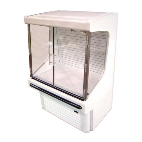
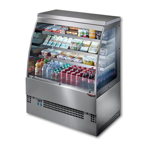
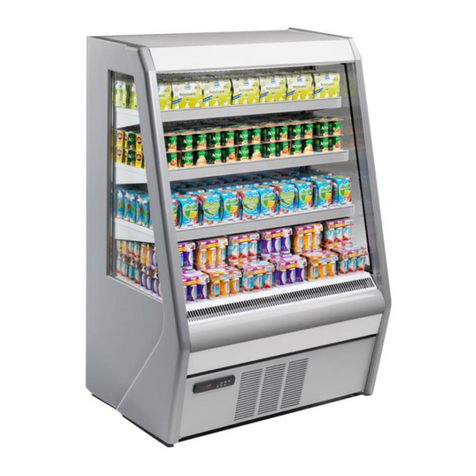
Hussmann Q3SSM6R User manual

Q3SSM4R,Q3SSM6R,Q3SSM8R,
Q3SSM10R, Q3SSM12R
Medium Temperature
Remote Cases
Installation &
Operation Manual
P/N 3068445_E
May 2022
IMPORTANT
Keep in store for
future reference!
MANUAL-I/O Q3 SSM RMT

INSTALLATION
ULListing . . . . . . . . . . . . . . . . . . . . . . . . . 1-1
Federal / State Regulation . . . . . . . . . . . .. 1-1
Hussmann Product Control . . . . . . . . . . . 1-1
Shipping Damage . . . . . . . . . . . . . . . . . .. 1-1
Location . . . . . . . . . . . . . . . . . . . . . . . . . . . 1-1
Clearances . . . . . . . . . . . . . . . . . . . . . . . . 1-2
Unloading . . . . . . . . . . . . . . . . . . . . . . . . . . . 1-3
Exterior Loading . . . . . . . . . . . . . . . . . . . . 1-3
Shipping Skid . . . . . . . . . . . . . . . . . . . . . . . 1-3
Merchandiser Leveling . . . . . . . . . . . . . . . 1-4
Serial Plate Location . . . . . . . . . . . . . . . . . 1-5
Start Up Check List . . . . . . . . . . . . . . . . . 1-6
ELECTRICAL /REFRIGERATION
Merchandiser Electrical Data . . . . . . . . . . 2-1
Field Wiring ........................ 2-1
Electrical Connections . . . . . . . . . . . . . . .. 2-1
Electrical Outlet ..................... 2-1
Wiring Color . . . . . . . . . . . . . . . . . . . . . . 2-2
Electrical Circuit Identification . . . . . . …2-2
Waste Outlet and P-TRAP. . . . . . . . . . ….. 2-2
START UP /OPERATION
Start up............................ 3-1
TEV Adjustment ....................3-1
Load Limits . . . . . . . . . . . . . . . . . . . . . . .. 3-1
Stocking . . . . . . . . . . . . . . . . . . . . . . . . . . . 3-1
Thermometer . . . . . . . . . . . . . . . . . . . . . .. 3-2
MAINTENANCE
Careand Cleaning ............ . . . . . . . 4-1
Removing Scratches from Bumper ......4-2
Cleaning Under Fan Plenum ..........4-2
Cleaning Discharge Air Louvers .......4-2
Cleaning Stainless Steel Surfaces . . . . . . . 4-3
Cleaning Coils ......................4-3
Self-Contained Refrigeration Equipment
Maintenance Check List . . . . . . . . . . . . . . 4-5
SERVICE
Replacing Fan Motors and Blades . . . . . . 5-1
Replacement Parts List . . . . . . . . . . . . . . . 5-2
APPENDIX
Technical Data..................... A-1
Shipping Weights. . . . . . . . . . . . . . . . . . . . A-2
Wiring Diagrams ...................A-3
Bumper Installation ............. .....A-8
WARRANTY
TABLE OF CONTENTS
ANSI Z535.5 DEFINITIONS . . . . . . . . . . iv
iii
HUSSMANN CORPORATION • BRIDGETON, MO 63044-2483 U.S.A. Q3 Remote Merchandisers

iv
REVISION HISTORY
REVISION D – Added Clearances, Page 1-2
REVISION D – Added model Q3SSM10R
REVISION C – updated load limit pictures
REVISION B – updated California Warning and
ABS drain fitting
REVISION A – ORIGINAL ISSUE
* * * * * * * * * * * * * * * * * * * * * * * * **
ANSI Z535.5 DEFINITIONS
•DANGER –Indicate[s] a hazardous
situation which, if not avoided, will
result in death or serious injury.
•WARNING –Indicate[s] a hazardous
situation which, if not avoided, could
result in death or serious injury.
•CAUTION –Indicate[s] a hazardous
situation which, if not avoided, could
result in minor or moderate injury.
•NOTICE –Not related to personal injury –
Indicates[s] situations, which if not avoided,
could result in damage to equipment.
!
!
!
3068445 _EU.S. & Canada 1-800-922-1919 • Mexico 1-800-890-2900 • www.hussmann.com

1-1
Q3 Remote Merchandisers
P/N 3068445 _E
UL LISTING
These merchandisers are manufactured to meet
ANSI/ UL 471 standard requirements for safe-
ty. Proper installation is required to maintain
the listing.
FEDERAL / STATE REGULATION
These merchandisers at the time they are man-
ufactured, meet all federal and state/ provincial
regulations. Proper installation is required to
ensure these standards are maintained. Near
the serial plate, each merchandiser carries a
label identifying the environment for which the
merchandiser was designed for use.
ANSI/NSF-7 Type I –Display Refrigerator /
Freezer
Intendedfor 75°F (24°C) / 55%RHAmbient Application
ANSI/NSF-7 Type II–DisplayRefrigerator /Freezer
Intended for 80°F / 55%RH Ambient Application
ANSI/NSF-7 –Display Refrigerator
Intended for Bulk Produce
HUSSMANN PRODUCT CONTROL
The serial number and shipping date of all
equipment is recorded in Hussmann’s files
for warranty and replacement part purposes.
All correspondence pertaining to warranty or
parts ordering must include the serial number
of each piece of equipment involved. This is to
ensure the customer is provided with the cor-
rect parts.
SHIPPING DAMAGE
All equipment should be thoroughly examined
for shipping damage before and during
unloading. This equipment has been carefully
inspected at our factory. Any claim for loss
or damage must be made to the carrier.The
carrier will provide any necessary inspection
reports and/or claim forms.
Apparent Loss or Damage
If there is an obvious loss or damage, it must
be noted on the freight bill or express receipt
and signed by the carrier’s agent; otherwise,
carrier may refuse claim.
Concealed Loss or Damage
When loss or damage is not apparent until
after equipment is uncrated, retain all packing
materials and submit a written response to the
carrier for inspection within 15 days.
LOCATION
These merchandisers are designed for
displaying products in air conditioned stores
where temperature is maintained at or below
the ANSI / NSF-7 specified level and relative
humidity is maintained at or below 55%.
Placing refrigerated merchandisers in direct
sunlight, near hot tables or near other heat
sources could impair their efficiency. Like
other merchandisers, these merchandisers are
sensitive to air disturbances. Air currents
passing around merchandisers will seriously
impair their operation. Do NOT allow air
conditioning, electric fans, open doors or
windows, etc. to create air currents around the
merchandiser.
INSTALLATION
Recommended operating ambient
temperature is between
65°F (18°C) to 75°F (23.9°C).
Maximum relative humidity is 55%.
HUSSMANN CORPORATION • BRIDGETON, MO 63044-2483 U.S.A.
1-2
Q3 Remote Merchandisers
P/N 3068445 _E
CLEARANCES
INSTALLATION
HUSSMANN CORPORATION • BRIDGETON, MO 63044-2483 U.S.A.
UNLOADING
Unloading from Trailer:
Lever Bar (also known as a Mule, Johnson Bar,
J-bar, Lever Dolly, or Pry Lever)
Move the merchandiser as close as possible to
its permanent location and remove all packaging.
Check for damage before discarding packaging.
Remove all separately packed accessories such
as kits and shelves.
Improper handling may cause damage to the
merchandiser when unloading.
To avoid damage:
1. Do not drag the merchandiser out ofthe
trailer. Use a Johnson bar (mule).
2. Use a forklift or dolly to remove the
merchandiser from the trailer.
1-3
EXTERIOR LOADING
Do NOT walk on top of merchandisers or
damage to the merchandisers and serious
personal injury could occur.
Merchandisers are not structurally
designed to support external loading
such as the weight of a person.
SHIPPING SKID
Each merchandiser is shipped on a skid to
protect the merchandiser’s base, and to make
positioning the case easier.
Remove the top of the crate and detach walls
from each other. Lift crate from the skid.
Unscrew the case from the skid. The fixture
can now be lifted off the crate skid. Lift only at
base of skid! Remove any braces and/or skids
attached (blanket wrapped merchandiser may
have skids).
DO NOT LAY MERCHANDISER OVER
ON THE FLOOR TO REMOVE SKID.
Once the skid is removed, the merchandiser
must be lifted —NOT PUSHED— to reposition.
To remove the skid, remove screws attaching
skid to the merchandiser.
Check floor where cases are to be set to see if
it is a level area. Determine the highest part of
the floor.
Do NOT remove shipping crate until the
merchandiser is positioned
for installation.
Do NOT stand or walk on top of
merchandiser. Do not store items or
flammable materials atop the unit.
Product should always be maintained at proper
temperature.This means that from the time
the product is received, through storage, prepa-
ration and display, the temperature of the
product must be controlled to maximize the
life of the product.
U.S.& Canada1-800-922-1919• Mexico1-800-890-2900•www.hussmann.com
P/N 3068445 _E

Installation
1. Using case blueprints, measure off and mark on the
floor the exact dimensions of where the cases will
sit.Snap chalk line for front and back positions of
base rail or pedestal.Mark the location of each joint
front and back.Find the highest point throughout the
lineup.FLOORS ARE NORMALLY NOT LEVEL!
Determine the highest point of the floor;cases will be
set off this point.All cases in the entire lineup must
be brought up to the highest level of the case sitting at
the highest point in the lineup.This may be done a
few different ways.
a) Walk the floor looking for any mounds or dips.
b) Use astringlevel.
c) Use atransit.
If awedge is used in the middle of alineup, the wedge
must be set on the highest point on the floor FIRST,
with the rest if the lineup being leveled from it.The
Q3-SSMcase has adjustable legs to allow for leveling.
2. Set first case over the highest part of the floor and
adjust legs so that case is level.Remove side and
back leg braces after case is set and joined.
3. Set second case within one foot (1') of the first case,
and remove leg skids.Keep the supports along the
length of the case and far end of case.Level case to
the first using the instructions in step one.
4. Apply masking tape 1/8" in from end of case on inside
and outside rear mullion and body work on both
cases to bejoined.
This equipment is to be installed
to comply with the applicable
NEC, Federal, State , and Local
Plumbing and Construction
Code that has jurisdiction.
ATTENTION
INSTALLER
6. Slide second case up to first case snugly.Then level
second case to the first case so glass front, bumper
and topare flush.
7. To compress butyl at joint, use two Jurgenson wood
clamps. Make sure case is level from front to back
and side to side on inside bulkheads at joint.
DO NOT USE PERMAGUM!
1-4 INSTALLATION
MERCHANDISER LEVELING
Be sure to position merchandisers properly.
Level the merchandiser by all four corners.
Merchandiser(s) must be installed level to ensure
proper operation of the refrigeration system, and to
ensure proper drainage of defrost water.
All cases were leveled and joined prior to shipment to
insure the closest possible fit when cases are joined in the
field. When joining, use a carpenters level and adjust legs
accordingly. The legs on the Q3-SS are adjustable and
do not require shims. Simply screw the leg up or down
to adjust height.
5. Apply liberal bead of case joint sealant
(butyl) to first case.Sealant area is shown using
adotted line in illustration in Step 8. Apply
heavy amount to cover entire shaded area.
DO NOT USE PERMAGUM!
Q3 Remote Merchandisers
HUSSMANN CORPORATION • BRIDGETON, MO 63044-2483 U.S.A.
P/N 3068445 _E

8. Attach sections together via the bolts pictured in the
illustration below.
9. Apply bead of butyl to top of bulk heads and slip on
stainless steel bulkhead cap.Also apply silicone to
seam between joints.
10. Use finger to smooth silicone as thin as possible at
masking tape on inside and outside of rear mullion
(apply additional silicone if necessary). Remove
tape applied on line #4.
11. Remove front, back and end shipping braces.
Q3-SS Refrigerated Wedges and Standard Cases Line up
taper pins and line-up plates with holes on adjoining case.
Bolting is located at the rear of the case, behind the air
discharge wall, and behind the front body panel. The cases
are bolted together in front by means of a bracket located
behind the front panel. Remove the front panel by
unscrewing these bottom screws.
LINE-UP PIN
(INSERT INTO
UPPER 1/2"HOLE)
CASE BOLTING
(USE 3/8"-16 x 1 1/2"
BOLT IN LOWERHOLE)
CASEBOLTING
(USE 3/8" -16 x 1
1/2" BOLT IN HOLE)
FRONT CASE BOLT
(USE 3/8"-16 x 1 1/2"
BOLT IN HOLE)
LINE-UP PLATE
(INSERT INTO
VERTICAL SLOT)
1-5P/N 3068445 _E
U.S.& Canada1-800-922-1919• Mexico1-800-890-2900•www.hussmann.com
SERIALPLATE LOCATION
The serial plate is located on the left side of
the Panel Lower Base Rmt as shown below.

Hussmann Self-Contained Refrigeration Equipment Start Up Check List
***Please note that failure to follow this start-up document may void your factory warranty***
Step Startup Activity Check
1Locate, read and maintain install/operation manual in asafe place for
future reference.
2Examine unit. Confirm there is NO damage or concealed damage.
3Level the unit, side to side and front to rear.
4Remove all shipping brackets/compressor straps/boltsetc.
5Unit must be run on adedicated electrical circuit without the use of
an extension cord.
6Ensure that the proper electrical requirements for the equipment are
supplied.
7Verify field electrical connections are tight.
8Verify all electrical wiring is secured and clear of any sharp edges or
hot lines.
9Verify the condensate drain line is properly trapped and pitched.
10 Verify all required clearances on the sides and back of unit.
11 Verify there are no air disturbances external to the unit. Heat and air
registers, fans, and doorsetc.
Advise owner/operator that merchandiser must operate at temperature for 24 hrs prior to loading
with product.
Form HSCW01 Rev. 30MAY12 P/N 0525209_B
LEGAL DISCLAIMER:
Hussmann shall not be liable for any repair or replacements made without the written consent of Hussmann, or when the product is installed or operated in amanner
contrary to the printed instructions covering installation and service which accompanied suchproduct.
1-6 INSTALLATION
Q3 Remote Merchandisers
HUSSMANN CORPORATION • BRIDGETON, MO 63044-2483 U.S.A.
P/N 3068445 _E

ELECTRICAL/ REFRIGERATION
Refer to the technical data sheets and merchandiser
serial plate for electrical information.
FIELD WIRING
Field wiring must be sized for component
amperes stamped on the serial plate.Actual
ampere draw may be less than specified.
ALWAYS CHECK THE SERIAL PLATE FOR
COMPONENT AMPERES
MERCHANDISER ELECTRICAL DATA ELECTRICAL OUTLET
Before the merchandiser is connected to any
wall circuit, use avoltmeter to check that the
outlet is at 100%of the rated voltage.The wall
circuit must be dedicated for the merchandis-
er.Failure to do so voids the warranty.Do
not use an extension cord.Never plug in more
than one merchandiser per electrical circuit.
ELECTRICAL CONNECTIONS
All wiring must be in compliance with NEC
and local codes.
•Always use a dedicated circuit with the
amperage stated on the unit.
•Plug into an outlet designed for the plug.
•Do not overload the circuit
•Do not use long or thin extensioncords.
Never use adapters.
•If in doubt, call an electrician.
2-1 ELECTRICAL/REFRIGERATION
Q3 Remote Merchandisers
HUSSMANN CORPORATION • BRIDGETON, MO 63044-2483 U.S.A.
P/N 3068445 _E

Wiring Color Code
StandardCaseWireColorCode
CASE MUST BE GROUNDED
NOTE:Refer to label affixed to case to determine the
actual configuration as checked in the “TYPE
INSTALLED” boxes.
Electrical Circuit Identification
Standard lighting for all models will be full length fluorescent
lamps located within the case at the top.The switch
controlling the lights, the plug provided for digital scale, and
the thermometer are located at the rear of the case mullion.
The receptacle that is provided on the exterior back of these
models is intended for computerized scales with afive amp
maximum load, not for large motors or other high wattage
appliances.It should be wired to adedicated circuit.
Electrical Service Receptacles (When Applicable) The
receptacles located on the exterior of the merchandiser are
intended for scales and lighted displays. They are not
intended nor suitable for large motors or other external
appliances.
Color Decsription Color
Ground Green
Anti-Sweat Purple
Lights Orange
Receptacles Yellow
T-Stat/Solenoid230VAC Red/Black
T-Stat/Solenoid115VAC White/Black
T-Stat/Solenoid24VAC Red/White
FanMotors Brown
Blue CondensingUnit
UseCopper ConductorsOnly
430-01-0338 R101003
DANGER
BEFORE SERVICING
ALWAYS DISCONNECT ELECTRICAL
POWER AT THE MAIN DISCONNECT
WHEN SERVICING OR REPLACING ANY
ELECTRICAL COMPONENT.
This includes (but not limited to) Fans, Heaters
Thermostats, and Lights.
2-2P/N 3068445 _E
Field Wiring and Serial Plate Amperage
Field Wiring must be sized for component amperes printed
on the serial plate. Actual ampere draw may be less than
specified. Field wiring from the refrigeration control panel to
the merchandisers is required for refrigeration thermostats.
Case amperes are listed on the wiring diagram, but always
check the serial plate.
LED Driver Location
Drivers are located within the access panel that runs the
length of the rear of the case. Refer to diagram on page 4.
Ashrae Color Code
NOTE: All other manufacturers have no standard sensor
codes.
Waste Outlet and P-TRAP
The waste outlet is located off the center of the case on
one side allowing drip piping to be run lengthwise under
the fixture.
A 1-1/2" P-TRAP and threaded adapter are supplied
with each fixture. The P-TRAP must be installed to
prevent air l eakage and i nsect entrance i nto t he fixture.
NOTE: For installation or maintenance of the P-TRAP,
use
only adhesive compatible with ABS fittings.
U.S.& Canada1-800-922-1919• Mexico1-800-890-2900•www.hussmann.com
Item # 18s279

3-1 START UP / OPERATION
START UP
Follow the controller start up procedures
as detailed in Section 3 of this manual.
Each self contained merchandiser has its
own evaporator coil and a pre-set
thermostatic expansion valve (TEV).
The TEV has been factory set at design
conditions to provide the recommended
performance.
TEVADJUSTMENT
Expansion valves may be adjusted to fully
feed the evaporator. Before attempting to
adjust valves, make sure the evaporator is
clear or only lightly covered with frost, and
the merchandiser is within 10°F of its
expected operating temperature.
Adjust the valve as follows:
a. Attach aprobe to the suction line near the
expansion valve bulb.
b. Obtain apressure reading from the factory
installed Schraeder valve. Convert the pres-
sure reading to asaturated temperature for the
refrigerant.
Temperature (b) minus Temperature (a) is the
superheat.The valve should be adjusted so that
the greatest difference between the two tem-
peratures is 3°F to 5°F.
Make adjustments of no more than 1/2turn of
the valve stem at atime and wait for at least
15 minutes before rechecking the probe tem-
perature and making further adjustments.
STOCKING
Product should NOT be placed inside the
merchandisers until merchandisers are at
proper operating temperature.
Allow merchandiser 24 hours to operate before
loading product.
Proper rotation of product during stocking is
necessary to prevent product loss.Always
bring the oldest product to the top and set the
newest to the bottom.
Air discharge and return flues must remain open
and free of obstruction at all times to provide
proper refrigeration and air curtain
performance.
Do not allow product, packages, signs, etc. to
block these grilles. Do not use non-approved
shelving, baskets, display racks, or any
accessory that could hamper air curtain
performance.
Do not allow product to be placed outside of
the designated load limits in the illustration.
Q3 Remote Merchandisers
HUSSMANN CORPORATION • BRIDGETON, MO 63044-2483 U.S.A.
P/N 3068445 _E
LOAD LIMITS
Each merchandiser has a load limit decal. Shelf
life of perishables will be short if load
limit is violated. See the following page for
load limit drawings.
At no time should merchandisers be
stocked beyond the load limits indicated.

THERMOMETER
Q-Series models have a solar thermometer.
The thermometer is located at the top
interior of the merchandiser.
Product will be degraded and may spoil if
allowed to sit in a non-refrigerated area.
3-2P/N 3068445 _E
U.S.& Canada1-800-922-1919• Mexico1-800-890-2900•www.hussmann.com
LOAD LIMIT
LOAD LIMIT

CAREAND CLEANING
Long life and satisfactory performance of
any equipment is dependent upon the care it
receives. To ensure long life, proper sanitation
and minimum maintenance costs, these
merchandisers should be thoroughly cleaned,
all debris removed and the interiors washed
down, weekly.
Exterior Surfaces
The exterior surfaces must be cleaned with a
mild detergent and warm water to protect and
maintain their attractive finish. Never use
abrasive cleansers or scouring pads.
Interior Surfaces
The interior surfaces may be cleaned with most
domestic detergents, ammonia based cleaners
and sanitizing solutions with no harm to the
surface.
Do NOT Use:
•Abrasive cleansers and scouring pads, as these
will mar the finish.
•Coarse paper towels on coated glass.
•Ammonia-based cleaners on acrylic parts.
•Remove the product and all loose debris to
avoid clogging the waste outlet.
•Store product in a refrigerated area such as a
cooler. Remove only as much product as can
be taken to the cooler in a timely manner.
•Disconnect electrical power before cleaning.
•Thoroughly clean all surfaces with soap and
hot water. Do Not use steam or high water
pressure hoses to wash the interior.
These will destroy the merchandisers’ sealing
causing leaks and poor performance.
•Take care to minimize direct contact between
fan motors and cleaning or rinse water.
•Do NOT flood merchandiser with water.
Never introduce water faster thanthe
waste outlet caN remove it.
•Allow merchandisers to dry before resuming
operation.
•After cleaning is completed, turn on power to
the merchandiser.
Do:
•Solvent, oil or acidic based cleaners on any
interior surfaces.
•Do not use high pressure water hoses.
Product will be degraded and may spoil if
allowed to sit in a non-refrigerated area.
Do NOT allow cleaning agent or
cloth to contact food product.
4-1 MAINTENANCE
Q3 Remote Merchandisers
HUSSMANN CORPORATION • BRIDGETON, MO 63044-2483 U.S.A.
P/N 3068445 _E

REMOVING SCRATCHES FROM
BUMPER
Most scratches and dings can be removed
using the following procedure.
1. Use steel wool to smooth out the surface
area of the bumper.
2. Clean area.
3. Apply vinyl or car wax and polish surface
for a smooth glossy finish.
CLEANING UNDER FAN PLENUM
After cleaning be sure the plenum is properly
lowered into position or producT loss will
resulT due to improper refrigeration.
CLEANING DISCHARGE AIR LOUVERS
Discharge air louvers should be cleaned every
six months. Dirty louvers will cause mer-
chandisers to perform poorly. The louvers
may be cleaned with a vacuum cleaner. Soap
and water may be used if all water is removed
from the louvers cells before replacing. Be care-
ful not to damage the louvers.
SHUT FANS OFF DURING
CLEANING PROCESS.
Do NOT use HOT water on Cold glass
Surfaces. This can cause the glass to
shatter and could result in personal
injury. Allow glass fronts, to warm
before applying hot water.
—LOCKOUT/ TAGOUT—
To avoid serious injury or death from electri-
cal shock, always disconnect the electrical
power at the main disconnect when servicing
or replacing any electrical component.This
includes, but is not limited to, such items as
doors, lights, fans, heaters, and thermostats.
4-2P/N 3068445 _E
U.S.& Canada1-800-922-1919• Mexico1-800-890-2900•www.hussmann.com

CLEANING STAINLESS STEELSURFACES
Use non-abrasive cleaning materials, and
always polish with grain of the steel.Use warm
water or add amild detergent to the water and
apply with acloth.Always wipe rails dry after
wetting.
Use alkaline chlorinated or non-chlorine
containing cleaners such as window cleaners
and mild detergents.Do not use cleaners
containing salts as this may cause pitting and
rusting of the stainless steel finish.Do not use
bleach.
CLEANING COILS
Condenser coils should be cleaned at least
once per month.Additional cleaning may be
needed depending on the operational environ-
ment. A dirty condenser blocks normal airflow
through the coils.
Airflow blockage increases energy consump-
tion and reduces the merchandiser’s ability to
maintain operating temperature.
To clean the coils, use avacuum cleaner with
awand attachment and asoft (non-metallic)
brush to remove dirt and debris.Do not bend
coil fins.Always wear gloves and protective
eye wear when cleaning near sharp coil fins
and dust particles.
DO NOT FLOOD!
Use only enough water necessary to clean
surface. Water must not drip down the case!
Never use ammonia based cleansers, abrasive
cleansers, or scouring pads.
4-3 MAINTENANCE
Q3 Remote Merchandisers
HUSSMANN CORPORATION • BRIDGETON, MO 63044-2483 U.S.A.
P/N 3068445 _E

NEVER USE SHARP OBJECTSAROUND
COILS. Use a soft brush or vacuum brush to
clean debris from coils. Do not puncture coils!
Do not bend fins. Contact an authorized
service technician if a coil is punctured,
cracked, or otherwise damaged.
ICE in or on the coil indicates the refrigera-
tion and defrost cycle is not operating prop-
erly. Contact an authorized service technician
to determine the cause of icing, and to make
adjustments as necessary. To maintain product
integrity, move all product to a cooler until
the unit has returned to normal operating
temperatures.
4-4P/N 3068445 _E
U.S.& Canada1-800-922-1919• Mexico1-800-890-2900•www.hussmann.com

* * * * * Warranty does not cover issues caused by improper installation or lack of basic preventative maintenance. *
* * * * Record starting date
Store Name and Number
Store Address
Unit Model Number
Unit Serial Number
Contractor/Technician
Technician
PM date
PMactivity-For visualinspection items,denote "ok or
complete" in the column to right when PM has been
performed.For measured data requested, record data
requested in the appropriate column to the right)
Quarterly Semi-
Annually Ql Q2 Q3 Q4 Ql Q2 Q3 Q4
Check in with store manager, record any complaints or issues
they have with unit. x
Lookunitover foranydamage,vibrationsorabnormalnoise. x
Verify unit is level side to side and front torear. x
Confirm refrigerant lines properly are secured and not touching or
rubbing other lines, wires or frame work. x
Verify fan motors and motor mounts are tight.x
Confirm fan blade/s are tight and not rubbing or hitting. x
Make sure all electrical connections, factory and field, aretight. x
Verify electrical connections at lamps are they secure anddry. x
Check for and replace any frayed or chaffed wiring. x
Check all electrical wiring make sure it is secured and not on
any sharp edges or hot lines. x
Check for air disturbances external l to the unit. Heat and air
registers, fans, and doorsetc. x
Check for waterleaks. x
Clean evaporator coil/s and fan blade/s. Do not use anacid
base cleaner. Rinse off any cleaner residue. x
Clean discharge air honeycombs or grilles. Do not use anacid
base cleaner. Rinse off anycleaner residue. x
Clean condenser coil/s and fan blade/s. Do not use an acidbase
Cleaner. Rinse off any cleanerresidue. x
Clean condensate drain pan and drain line. x
Verify condensate drain lines are clear andfunctioning. x
Record voltage reading at unit with unit off? x
Verify condenser and evaporator fans areworking. x
Record condenser air inlettemperature x
Record condenser air outlet temperature x
Is condenser air inlet or air exhaust restricted orrecirculating? x
Verify there are no visual oil or refrigerant leaks. x
Record voltage reading with unitrunning. x
Record compressor ampdraw. x
Record defrost heater voltage and amp draw. x
Record anti-sweat heater voltage and amp draw. x
Record case producttemperature. x
Record unit discharge air temperature. x
Record unit return air temperature. x
Record ambient conditions around unit (wet Bulb temperature
and dry bulb temperature). x
Check product loading, do not load beyond the units loadlimits. x
Verify clearances on sides/back ofunit. x
Check unit controller for proper operation. See controller or 1/0
Manual for proper controller operation.x
Confirm door switchesfunction. x
Verify unit doors and lids work and are sealedcorrectly. x
Verify that all the panels, shields and covers are in place. x
Technician Notes:
Form HSCW03 Rev-29 OCTOBER13 P/N 0525210_C
4-5 MAINTENANCE
Q3 Remote Merchandisers
HUSSMANN CORPORATION • BRIDGETON, MO 63044-2483 U.S.A.
P/N 3068445 _E
This manual suits for next models
6
Table of contents
Other Hussmann Display Case manuals

Hussmann
Hussmann PSM15E3R User manual

Hussmann
Hussmann ISM Operating instructions

Hussmann
Hussmann PMM20F3R User manual

Hussmann
Hussmann RBB Operating instructions

Hussmann
Hussmann ISLA Original operating instructions

Hussmann
Hussmann AB Operating instructions

Hussmann
Hussmann DCCG-8 Quick guide

Hussmann
Hussmann DM LOW HEIGHT Series User manual

Hussmann
Hussmann Austral H1 User manual

Hussmann
Hussmann Chino DBP Series Original operating instructions