Hussmann Q2SSNM4SPA User manual

Q2SSNM4SPA
Medium Temperature
Self Contained
P/N 3091736_C
October 2020
Installation &
Operation Manual
®
Æ
Spanish 3091737
WARNINGS:
If the information in these instructions are not followed
exactly, a fire or explosion may result, causing property
damage, personal injury or death.
Installation and service must be performed by a qualified
installer or service agency.
READ THE ENTIRE MANUAL BEFORE
INSTALLING OR USING THIS EQUIPMENT.
The unit uses R-290 (propane) gas as the refrigerant.
R-290 (propane) is flammable and heavier than air. It
collects first in low areas but can be circulated by the
fans. If propane gas is present or even suspected, do not
allow untrained personnel to attempt to find the cause.
The propane gas used in the unit has no odor. The lack
of smell does not indicate a lack of escaped gas. If a
leak is detected, immediately evacuate all persons from
the store, and contact the local fire department to advise
them that a propane leak has occured. Do not let any
persons back into the store until the qualified service
technician has arrived and that technician advises that it
is safe to return to the store. No open flames, cigarettes
or other possible sources of ignition should be used
inside or in the vicinity of the units.
FAILURETOABIDE BYTHIS WARNING COULD
RESULT IN AN EXPLOSION, DEATH, INJURY AND
PROPERTY DAMAGE.
IMPORTANT
Keep in store for future reference!
MANUAL-SELFCONTAINED Q2SSNM4SPA

2
P/N 3091736_C U.S. & Canada 1-800-922-1919 • Mexico 1 800-890-2900 • www.hussmann.com
BEFORE YOU BEGIN
Read these instructions completely and carefully.
PERSONAL PROTECTION EQUIPMENT (PPE)
Personal Protection Equipment (PPE) is required whenever installing or servicing this
equipment. Always wear safety glasses, gloves, protective boots or shoes, long pants, and a
long-sleeve shirt.
1. If the information in these instructions are not followed exactly, a re or explosion may result, causing property damage, personal
injury or death.
2. Installation and service must be performed by a qualied installer or service agency.
3. This unit is designed only for use with R-290 (propane) gas as the designated refrigerant.
THE REFRIGERANT LOOP IS SEALED. ONLY A QUALIFIED TECHNICIAN SHOULDATTEMPT TO SERVICE!
• Propane is ammable and heavier than air.
• It collects rst in the low areas but can be circulated by the fans.
• If R-290 (propane) is present or even suspected, do not allow untrained personnel to attempt to nd the cause.
• The propane gas used in the unit has no odor.
• The lack of smell does not indicate a lack of escaped gas.
• If a leak is detected, immediately evacuate all persons from the store, and contact the local re department to advise them that a pro
pane leak has occured.
• Do not let any persons back into the store until the qualied service technician has arrived and that technician advises that it is safe to
return to the store.
• A hand-held propane leak detector (“sniffer”) shall be used before any repair and/or maintenance.
• No open ames, cigarettes or other possible sources of ignition should be used inside the building where the units are located until
the qualied service technician and/or local re department determines that all propane has been cleared from the area and from the
refrigeration systems.
• Component parts are designed for propane and non-incendive and non-sparking. Component parts shall only be replaced with identical
repair parts.
FAILURE TOABIDE BY THIS WARNING COULD RESULT IN AN EXPLOSION, DEATH, INJURY AND PROPERTY DAMAGE.

P/N 3091736_C 3
ANSI Z535.5 DEFINITIONS ............. iv
INSTALLATION
NSF Listing ............................. 5
Federal / State Regulations ................. 5
Hussmann Product Control ................ 5
Shipping Damage ........................ 5
Location ................................ 5
Self Contained Location ................... 6
Unloading .............................. 6
Exterior Loading ......................... 6
Shipping Skid/Crate ...................... 7
Merchandiser Leveling .................... 7
Serial Plate Location ...................... 7
Refrigeration Unit Access .................. 8
Sealing Merchandiser to Floor .............. 8
Merchandiser Electrical Data ............... 8
Field Wiring ............................. 8
Power Switch ............................ 8
Electrical Connections . . . . . . . . . . . . . . . . . . . . . 8
Electrical Outlet .......................... 9
Refrigeration ............................ 9
Before Beginning Service or Repair ......... 10
Replacing Refrigeration System ............ 11
Steps to Recover Refrigerant............... 11
Charging .............................. 12
Sensor to Control Configuration ........... 13
START UP / OPERATION
Controller Operation ..................... 14
Controller Data ......................... 17
Start Up ............................... 18
Controls and Adjustments ................ 18
Self-Contained Startup Checklist ........... 19
Load Limits ............................ 20
Stocking ............................... 20
Thermometer ........................... 20
MAINTENANCE
Care and Cleaning ....................... 21
Cleaning Discharge Honeycomb ........... 23
Cleaning Stainless Steel Surfaces ........... 23
Cleaning Solar Thermometer .............. 23
Cleaning Under Display Pan .............. 24
Cleaning Evaporation Pan ................ 24
Cleaning Coils .......................... 25
Removing Scratches from Bumper .......... 25
Self-Contained Refrigeration Equipment
Maintenance Checklist................... 26
SERVICE
Replacing Fan Motors and Blades .......... 27
WARRANTY
TABLE OF CONTENTS
IMPORTANT
KEEP IN STORE FOR FUTURE REFERENCE
Quality that sets industry standards!
12999 St. Charles Rock Road • Bridgeton, MO 63044-2483
U.S. & Canada 1-800-922-1919 • Mexico 1-800-890-2900
www.hussmann.com
© 2020 Hussmann Corporation

4
P/N 3091736_C U.S. & Canada 1-800-922-1919 • Mexico 1 800-890-2900 • www.hussmann.com
REVISION HISTORY
REVISION C — Removed tech data; updated warnings
REVISION B — Added Warnings
ORIGINAL ISSUE — APRIL 2019
* * * * * * * * * * * * * * * * * * * * * * * * * *
ANSI Z535.5 DEFINITIONS
• DANGER – Indicate[s] a hazardous
situation which, if not avoided, will
result in death or serious injury.
• WARNING –Indicate[s] a hazardous
situation which, if not avoided, could
result in death or serious injury.
• CAUTION –Indicate[s] a hazardous
situation which, if not avoided, could
result in minor or moderate injury.
• NOTICE – Not related to personal injury –
Indicates[s] situations, which if not avoided,
could result in damage to equipment.
Merchandiser must operate for 24 hours
before loading product!
Regularly check merchandiser temperatures.
Do not break the cold chain. Keep products
in freezer before loading into merchandiser.
These merchandisers are designed
for only pre-frozen products.
AT TENTION
Merchandiser must operate for 24 hours
before loading product!
Regularly check merchandiser temperatures.
Do not break the cold chain. Keep products in
cooler before loading into merchandiser.
These merchandisers are designed
for only pre-chilled products.
— LOCK OUT / TAG OUT —
To avoid serious injury or death from electrical
shock, always disconnect the electrical power
at the main disconnect when servicing or
replacing any electrical component. This
includes, but is not limited to, such items as
doors, lights, fans, heaters, and thermostats.
Case ventilation openings must be clear of any
obstructions. Do not damage the refrigerant
circuit.
Do not use mechanical devices or other means
to accelerate the defrosting process.
Do not use electrical appliances inside the food
storage compartments of the case.
All installation and operating instructions
concerning the handling, moving, and use of
these merchandisers must be carefully followed
to avoid either damaging the refrigerant tubing,
or increasing the risk of a leak.

P/N 3091736_C 5
HUSSMANN CORPORATION • BRIDGETON, MO 63044-2483 U.S.A. Q2SSNM4SPA Merchandisers
NSF LISTING
These merchandisers are manufactured to meet
ANSI / UL 471 standard requirements for
safety. Proper installation is required to main-
tain this listing. Near the serial plate, each case
carries a label identifying the type of conditions
for which the merchandiser was tested.
ANSI/NSF-7 Type I – Display
Refrigerator / Freezer Intended for
75°F / 55% RH Ambient Application
ANSI/NSF-7 Type II – Display
Refrigerator / Freezer Intended for
80°F / 55% RH Ambient Application
ANSI/NSF-7 – Display Refrigerator
Intended for Bulk Produce
FEDERAL / STATE REGULATION
These merchandisers, at the time they are
manufactured, meet all federal and state /
provincial regulations.
HUSSMANN PRODUCT CONTROL
The serial number and shipping date of all
equipment is recorded in Hussmann’s files
for warranty and replacement part purposes.
All correspondence pertaining to warranty or
parts ordering must include the serial number
of each piece of equipment involved. This is to
ensure the customer is provided with the cor-
rect parts.
SHIPPING DAMAGE
All equipment should be thoroughly examined
for shipping damage before and during
unloading. This equipment has been carefully
inspected at our factory. Any claim for loss or
damage must be made to the carrier. The
carrier will provide any necessary inspection
reports and/or claim forms
Apparent Loss or Damage
If there is an obvious loss or damage, it must
be noted on the freight bill or express receipt
and signed by the carrier’s agent; otherwise,
carrier may refuse claim.
Concealed Loss or Damage
When loss or damage is not apparent until
after equipment is uncrated, retain all packing
materials and submit a written response to the
carrier for inspection within 15 days.
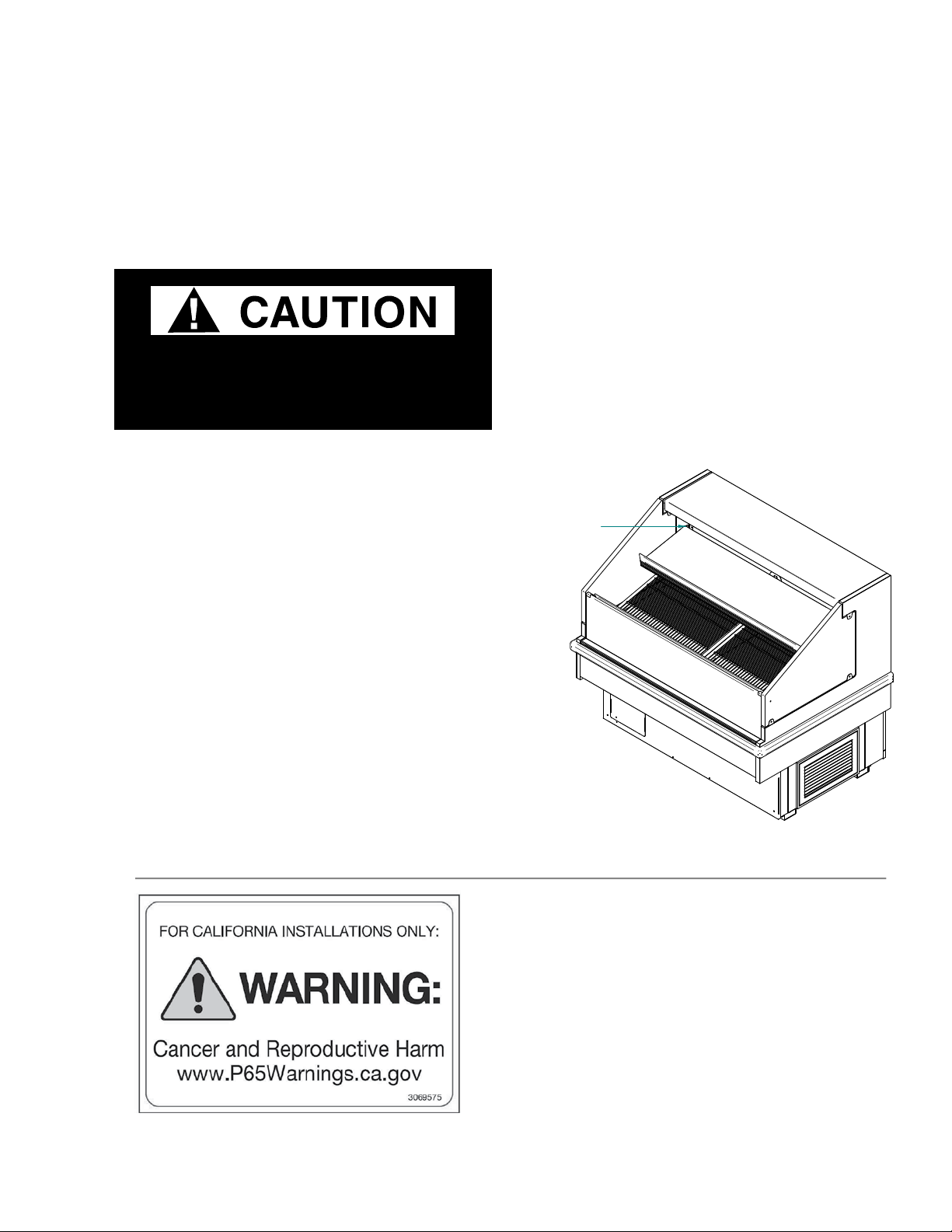
LOCATION
These merchandisers are designed for
displaying products in air conditioned stores
where temperature is maintained at or below
the ANSI / NSF-7 specified level and relative
humidity is maintained at or below 55%.
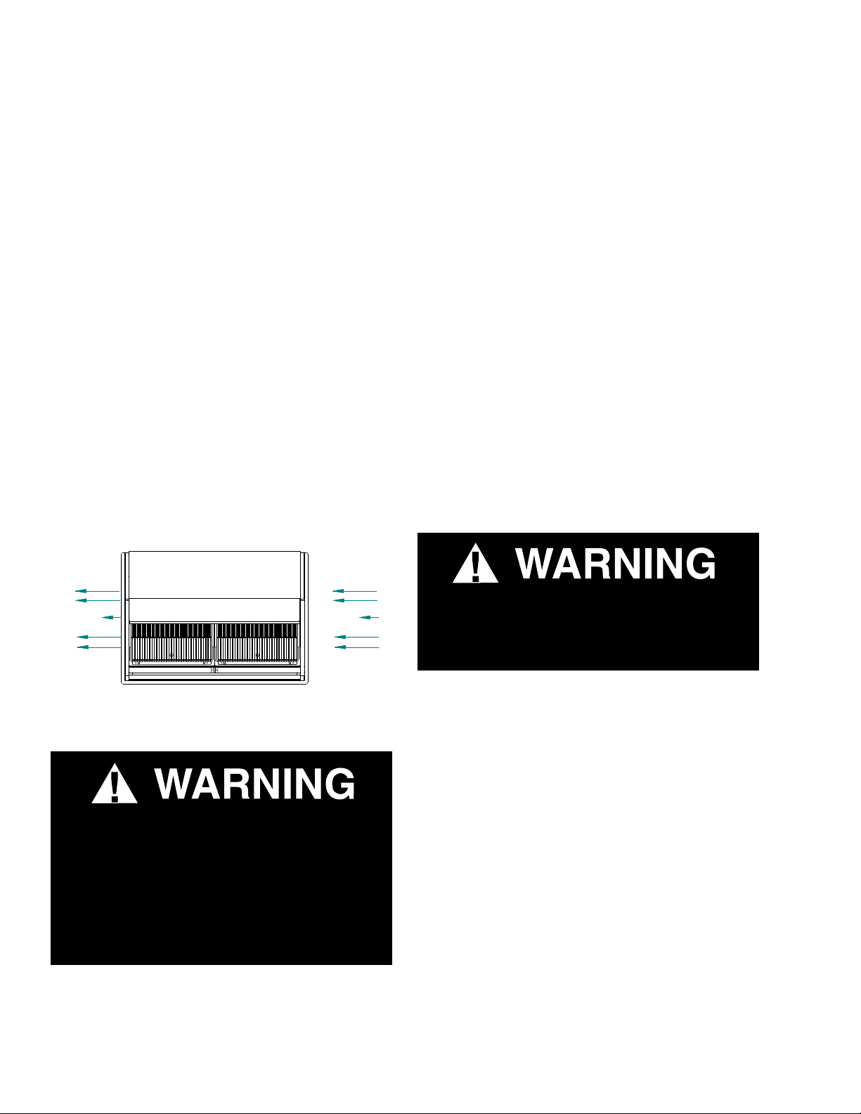
Placing refrigerated merchandisers in direct
sunlight, near hot tables or near other heat
sources could impair their efficiency. Like
other merchandisers, these merchandisers are
sensitive to air disturbances. Air currents
passing around merchandisers will seriously
impair their operation. Do NOT allow air
conditioning, electric fans, open doors or
windows, etc. to create air currents around the
merchandiser.
Recommended operating ambient
temperature is between
65°F (18°C) to 75°F (23.9°C).
Maximum relative humidity is 55%.
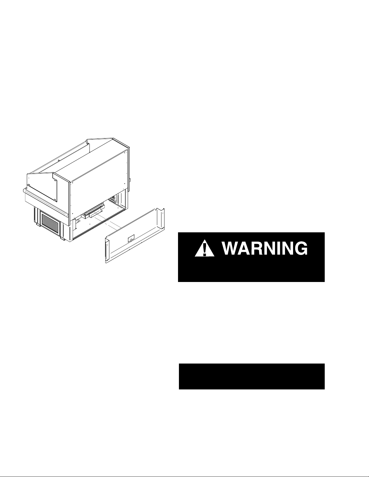
INSTALLATION

6
P/N 3091736_C U.S. & Canada 1-800-922-1919 • Mexico 1 800-890-2900 • www.hussmann.com
SELF CONTAINED (LOCATION)
Product should always be maintained at proper
temperature. This means that from the time
the product is received, through storage, prepa-
ration and display, the temperature of the
product must be controlled to maximize the
life of the product.
Besure to position self contained
merchandisers properly.
SELF CONTAINED models have vented base
panels to allow air circulation through the
condensing unit. Allow for a minimum 4 in.
clearance from walls, merchandisers, and any
other large objects near the merchandiser’s
vented base panels (for self contained models).
Blocking or restricting air flow will adversely
affect performance and may damage the refrig-
eration system.
UNLOADING
Unloading from Trailer:
Lever Bar (also known as a Mule, Johnson
Bar, J-bar, Lever Dolly, or Pry Lever)
Move the merchandiser as close as possible to
its permanent location and remove all packaging.
Check for damage before discarding packaging.
Remove all separately packed accessories such
as kits and shelves.
Improper handling may cause damage to the
merchandiser when unloading. To avoid damage:
1. Do not drag the merchandiser out of the
trailer. Use a Johnson bar (mule).
2. Use a forklift or dolly to remove the
merchandiser from the trailer.
EXTERIOR LOADING
Do NOT walk on top of merchandisers or
damage to the merchandisers and serious
personal injury could occur.
merchandisers are not structurally
designed to support external loading
such as the weight of a person. Do not place
heavy objects on the merchandiser.
FRONT
REAR
AIR EXHAUST
AIR EXHAUST AIR INTAKE Do NOT stand or walk on top of
merchandiser. Do not store items or
ammable materials atop the unit.
— LOCK OUT / TAG OUT —
To avoid serious injury or death from electri-
cal shock, always disconnect the electrical
power at the main disconnect when servicing
or replacing any electrical component. This
includes, but is not limited to, such items as
doors, lights, fans, heaters, and thermostats.

P/N 3091736_C 7
HUSSMANN CORPORATION • BRIDGETON, MO 63044-2483 U.S.A. Q2SSNM4SPA Merchandisers
SHIPPING SKID
Each merchandiser is shipped on a skid to
protect the merchandiser’s base, and to make
positioning the case easier. The skid provides
protection for both the merchandiser and the
floor.
Remove the skid by raising one end of the
merchandiser approximately 6 inches. Block the
merchandiser securely, and remove the two skid
bolts from the raised end. Replace the bolts
with (provided) leg levelers. Repeat this proce-
dure at opposing end. Once the leg levelers are
secured in place, the merchandiser may be slid
off the skid and placed in its final location.
DO NOT TILT MERCHANDISER ON ITS
SIDE OR END WHEN REMOVING SKID.
Once the skid is removed, the merchandiser
must be lifted —NOT PUSHED— to reposition.
Check floor where merchandisers are to be set
to see if it is a level area. Determine the highest
part of the floor.
MERCHANDISER LEVELING
Besure to position merchandisers properly.
Level the merchandiser by all four corners.
Merchandiser(s) must be installed level to
ensure proper operation of the refrigeration
system, and to ensure proper drainage of
defrost water.
SERIAL PLATE LOCATION
The serial plate is located on the inside of the
merchandiser’s display area as shown below.
Do NOT remove shipping crate until the
merchandiser is positioned
for installation.
SERIAL PLATE
REMOVE REAR PANEL
This warning does not mean that Hussmann products
will cause cancer or reproductive harm, or is in
violation of any product-safety standards or
requirements. As clarified by the California State
government, Proposition 65 can be considered more of
a‘right to know’ law than a pure product safetylaw.
When used as designed, Hussmann believes that our
products are notharmful. We provide the Proposition
65 warning to stay in compliance with California State
law. It is your responsibility to provide accurate
Proposition 65 warning labels to your customers when
necessary. For more information on Proposition 65,
please visit the California State government website.
August 31, 2018

8
P/N 3091736_C U.S. & Canada 1-800-922-1919 • Mexico 1 800-890-2900 • www.hussmann.com
REFRIGERATION UNIT ACCESS
The rear front panel may be removed by lifting
the panel straight upward and over the tabs
on which it is hanging. Screws will have to
be removed from either end of the panel. The
panel is installed by reversing the above procedure.
Ensure lower front panel is flat against the
floor when installed to prevent air circulation
problems.
SEALING MERCHANDISER TO FLOOR
If required by local sanitary codes, or if the
customer desires, merchandisers may be sealed
to the floor using a vinyl cove base trim. The
size needed will depend on how much varia-
tion there is in the floor, from one end of the
merchandiser to the other. Sealing of the lower
front and rear panels on self contained mod-
els may hamper their removal for servicing or
maintenance of the condensing unit.
NOTE: Do not allow trim to cover any intake
or discharge grilles located in the lower front
panel.
MERCHANDISER ELECTRICAL DATA
Refer to the merchandiser’s serial plate for
electrical information.
FIELD WIRING
Field wiring must be sized for component
amperes stamped on the serial plate. Actual
ampere draw may be less than specified.
POWER SWITCH
The main electrical power switch is located
behind the front louvered access panel. The
power switch must be turned OFF before
servicing the merchandiser.
ELECTRICAL CONNECTIONS
All wiring must be in compliance with NEC
and local codes. This model is provided with a
power cord.
ALWAYS CHECK THE SERIAL PLATE FOR
COMPONENT AMPERES
Merchandiser must be grounded.
Do not remove the power supply cord ground.
SERIAL PLATE
REMOVE REAR PANEL

P/N 3091736_C 9
HUSSMANN CORPORATION • BRIDGETON, MO 63044-2483 U.S.A. Q2SSNM4SPA Merchandisers
ELECTRICAL OUTLET
Before the merchandiser is connected to any
wall circuit, use a voltmeter to check that the
outlet is at 100% of the rated voltage. The wall
circuit must be dedicated for the merchandiser.
Failure to do so voids the warranty. Do not
use an extension cord. Never plug in more
than one merchandiser per electrical circuit.
• Always use a dedicated circuit with the
amperage stated on the unit.
• Plug into an outlet designed for the plug.
• Do not overload the circuit
• Do not use long or thin extension cords.
Never use adapters.
• If in doubt, call an electrician.
This model has a factory-installed power cord that
is attached at the electrical box.
REFRIGERATION
(Self Contained Models)
Each self contained model is equipped with
its own condensing unit and control panel
located beneath the display area. The correct
type of refrigerant will be stamped on each
merchandiser’s serial plate. The refrigeration
piping is leak tested. The unit is charged with
refrigerant, and shipped from the factory with
all service valves open.
Self contained models have a refrigeration
system that uses a hermetic compressor. This
model uses a capillary tube for refrigerant
control. The capillary tube is soldered to
the suction line pull-out coil for proper
heat exchange. If the capillary should become
plugged or damaged, it is best to replace the
heat exchanger.
For self contained models like, this water seal
drains into a condensate pan located beneath
the merchandiser. Ensure the drain hose is
properly trapped, and the drain area is not
clogged.
NOTE: All lower base panels must be in place
when the refrigerator is operating. If panels are
not in place airflow from the condenser will not be
directed over the evaporator pan and defrost water
in the pan may overflow.
Risk of Electric Shock. If cord or plug
becomes damaged, replace only with
a cord and plug of the same type.

10
P/N 3091736_C U.S. & Canada 1-800-922-1919 • Mexico 1 800-890-2900 • www.hussmann.com
Before Beginning Any Service or Repair:
Use a hand-held propane leak detector (“sniffer”)
to ensure no propane is present in the immedi-
ate area, the inside of the display case and the
inside of the refrigeration system. R-290 is an
odorless refrigerant. Keep the area clear of all
customers and non-essential or unauthorized
personnel.
Verify that all repair parts are identical models
to the ones they are replacing. Do not substitute
parts such as motors, switches, relays, heaters,
compressors, power supplies or solenoids. Fail-
ure to do so can result in an explosion, death,
injury and property damage. Parts used on
hydrocarbon cases must meet specic UL certi-
cation for non-incendive or non-sparking com-
ponents. Use only Hussmann approved parts
approved through the Hussmann Performance
Parts Website. https://parts.hussmann.com/
Brazing must not begin before all propane has
been cleared from the immediate area — the
inside of the displays case and the inside of the
refrigeration system.
If a leak is detected, follow store safety proce-
dures. It is the store’s responsibility to have a
written safety procedure in place. The safety
procedure must comply with all applicable codes
such as local fire department’s codes.
At minimum, the following actions are required:
• Immediately evacuate all persons from the
store, and contact the local fire department to
advise them that a propane leak has occured.
• Call Hussmann and/or a qualified service
agent and inform them that a propane sensor
has detected the presence of propane.
• Do not let any persons back into the store
until the qualified service technician has arrived
and that technician advises that it is safe to re-
turn to the store.
• The propane gas used in the unit has no
odor. The lack of smell does not indicate a lack
of escaped gas.
• A hand-held propane leak detector
(“sniffer”) should be used before any repair and/
or maintenance is attempted. All repair parts
must be identical models to the ones they are
replacing.
• No open flames, cigarettes or other possible
sources of ignition should be used inside the
building where the units are located until the
qualified service technician and/or local fire de-
partment determines that all propane has been
cleared from the area and from the refrigeration
systems.
Only Hussmann or factory
trained technicians should
service or repair this R-290
(propane) equipment.
Failure to follow
instructions can result in
an explosion, death, injury
and property damage.

P/N 3091736_C 11
HUSSMANN CORPORATION • BRIDGETON, MO 63044-2483 U.S.A. Q2SSNM4SPA Merchandisers
REPLACING REFRIGERATION SYSTEM
COMPONENTS
STEPS TO RECOVER REFRIGERANT
1. Make sure you are in a well ventilated area be-
fore making any service or repair to the refriger-
ation system.
2. Disconnect all power sources from the system.
Some systems may have more than one plug or
power supply.
3. Tap system with line tap valves, attaching gauges to
the high and low sides of the system.
4. Connect hose to an evacuated recovery tank.
Open refrigeration gauges and recovery tank.
5. With the suction valve in vacuum, the refrigerant will
be recovered into the recovery tank.
6. Once recovered, close the tank valve and remove
the guage from the tank and connect nitrogen tank
to the system to purge it with nitrogen.
7. Pull vacuum to a minimum of 200 microns or
lower.
Only Hussmann service technicians or
technicians qualied to handle R-290
(propane) refrigerant should service or
repair this R-290 (propane) equipment
Failure to follow instructions can result
in an explosion, death, injury
and property damage.
refrigeration
line tapping
valve

12
P/N 3091736_C U.S. & Canada 1-800-922-1919 • Mexico 1 800-890-2900 • www.hussmann.com
CHARGING
A calibrated scale with +/-2 gram accuracy
must be used to charge the system. The charge
amount is shown on the serial plate. Only R-290
grade refrigerant can be used. Standard propane
does not meet the purity/moisture content of
R-290, and therefore cannot be used to charge
cases.
No gas charge adjustments are allowed. When
connecting hoses between the refrigeration sys-
tem, manifold gauges, and refrigerant cylinder,
ensure that the connections are secure and there
are no potential sources of ignition nearby. En-
sure that contamination of different refrigerants
does not occur when using charging equipment.
Use dedicated hoses to service R-290 (propane)
refrigeration systems. Hoses or lines should be
as short as possible to minimize the amount of
refrigerant contained in them.
Ensure that the refrigeration system is properly
grounded prior to charging the system with
refrigerant, to avoid the potential for static
build-up.
Extreme care must be taken not to overfill the
refrigeration system. After charging, carefully
disconnect the hoses, attempting to minimize
the quantity of refrigerant released. Further
leak check the service ports, hoses, refrigerant
tanks. The service ports shall be checked for
leaks using a hydrocarbon leak detector with a
sensitivity of 3 grams/year (0.106 Oz/year) leak
rate.
Thoroughly leak check the service ports. If no
leak is present, use a pinch-off tool to close the
ends of the service tubes before brazing them
shut. Remove all service ports. If a Schrader
valve is used on the compressor service tube, it
must be removed and the previous steps fol-
lowed in order to braze the service tube shut.
Component parts shall be replaced with like
components, and servicing shall be done by
factory authorized service personnel only, so
as to minimize the risk of possible ignition
due to incorrect parts or improper service.

P/N 3091736_C 13
HUSSMANN CORPORATION • BRIDGETON, MO 63044-2483 U.S.A. Q2SSNM4SPA Merchandisers
Typical Sensor to Control Conguration
TEMPERATURE
SENSOR
DEFROST
SENSOR
THERMOSTAT
SOLID STATE RELAY
MAIN SWITCH
POWER
CORD
CONTROL BOX
CONTROL BOX ASSY MAY INCLUDE:
-LED POWER
SUPPLY
TEMPERATURE
SENSOR
DEFROST
SENSOR
THERMOSTAT
SOLID STATE RELAY
MAIN SWITCH
POWER
CORD
CONTROL BOX
CONTROL BOX ASSY MAY INCLUDE:
-LED POWER
SUPPLY

14
P/N 3091736_C U.S. & Canada 1-800-922-1919 • Mexico 1 800-890-2900 • www.hussmann.com
Controller Operation
Display
The values will be shown with three digits, and
with a setting you can determine whether the
temperature are to be shown in °C or in °F.
Light-emitting diodes (LED) on front panel
HACCP = HACCP function is active
The other LED’s on the front panel will light up
when the belong- ing relay is activated.
= Refrigeration
= Defrost
= Fan running
The light-emitting diodes will ash when there is
an alarm.
In this situation you can download the error
code to the display and cancel/sign for the alarm
by giving the top knob a brief push.
The Buttons
When you want to change a setting, the upper
and the lower buttons will give you a higher or
lower value depending on the button you are
pushing. But before you change the value, you
must have access to the menu. You obtain this
by pushing the upper button for a couple of
seconds - you will then enter the col- umn with
parameter codes. Find the parameter code you
want to change and push the middle buttons
until value for the parameter is shown. When
you have changed the value, save the new value
by once more pushing the middle button.
Examples
Set menu
1. Push the upper button until a parameter r01
is shown
2. Push the upper or the lower button and nd
that parameter you want to change
3. Push the middle button until the parameter
value is shown
4. Push the upper or the lower button and select
the new value
5. Push the middle button again to freeze the
value.
Cutout alarm relay / receipt alarm/see alarm
code
• Push short the upper button
If there are several alarm codes they are found
in a rolling stack. Push the uppermost or lower-
most button to scan the rolling stack.
Set temperature
1. Push the middle button until the temperature
value is shown
2. Push the upper or the lower button and select
the new value
3. Push the middle button again to conclude the
setting.
Reading the temperature at defrost sensor
• Push short the lower button
Manual start or stop of a defrost
• Push the lower button for four seconds.
(Though not for application 4).
Reprinted with permission from the controller manufacturer.
START UP / OPERATION

P/N 3091736_C 15
HUSSMANN CORPORATION • BRIDGETON, MO 63044-2483 U.S.A. Q2SSNM4SPA Merchandisers
Defrost
During defrost a –d- is shown in the display.
This view will con- tinue up till 15 min. after the
cooling has resumed.
However the view of –d- will be discontinued if:
-The temperature is suitable within the 15 minutes
-The regulation is stopped with “Main Switch”
-A high temperature alarm appears
Alarms
The controller can give alarm in different situa-
tions. When there is an alarm all the light-emit-
ting diodes (LED) will ash on the controller
front panel, and the alarm relay will cut in.
Upper alarm limit
Here you set when the alarm for high temperature
is to start. The limit value is set in °C (absolute
value). The limit value will be raised during
night operation. The value is the same as the
one set for night setback, but will only be raised
if the value is positive.
The limit value will also be raised in connection
with reference displacement r39.
Lower alarm limit
Here you set when the alarm for low tempera-
ture is to start. The limit value is set in °C (abso-
lute value). The limit value will also be raised in
connection with reference displacement r39.
Signal to the alarm thermostat
Here you have to dene the ratio between the
sensors which the alarm thermostat has to use.
S3, S4 or a combination of the two.
With setting 0% only S3 is used. With 100%
only S4 is used.
Connections
Power supply
115 V a.c.
Sensors
S3 and S4 are thermostat sensors.
A setting determines whether S3 or S4 or both
of them are to be used.
S5 is a defrost sensor and is used if defrost has
to be stopped based on temperature.
Digital On/Off signals
A cut-in input will activate a function. The pos-
sible functions are described in menus o02 and
o37.
External display
Connection of display type EKA 163A (EKA
164A).
Relays
The general uses are mentioned here. See also
page 6 where the different applications are
shown.
DO1: Refrigeration. The relay will cut in when
the controller demands refrigeration
DO2: Defrost. The relay will cut in when defrost
is in progress

16
P/N 3091736_C U.S. & Canada 1-800-922-1919 • Mexico 1 800-890-2900 • www.hussmann.com
Product will be degraded and may spoil if
allowed to sit in a non-refrigerated area.
DO3: For either fans or refrigeration 2
Fans: The relay will cut in when the fans have
to operate Refrigeration 2: The relay will cut in
when refrigeration step 2 has to be cut in
DO4: For either alarm, rail heat, light or hotgas defrost
Alarm: Cf. diagram. The relay is cut in
during normal opera- tion and cuts out in
alarm situations and when the controller is
dead (de-energised)
Rail heat: The relay cuts in when rail heat
is to operate
Light: The relay cuts in when the light has
to be switched on Hotgas defrost: See dia
gram. The relay will cut out when defrost
has to be done.
Data communication
The controller is available in several versions
where data com- munication can be carried out
with one of the following systems: MOD-bus or
LON-RS485.
If data communication is used, it is important
that the installation of the data communication
cable is performed correctly.
See separate literature No. RC8AC…
Electric noise
Cables for sensors, DI inputs and data com-
munication must be kept separate from other
electric cables:
- Use separate cable trays
- Keep a distance between cables of at least 10 cm
- Long cables at the DI input should be avoided

P/N 3091736_C 17
HUSSMANN CORPORATION • BRIDGETON, MO 63044-2483 U.S.A. Q2SSNM4SPA Merchandisers

18
P/N 3091736_C U.S. & Canada 1-800-922-1919 • Mexico 1 800-890-2900 • www.hussmann.com
START UP
The self contained merchandiser has its own
evaporator coil and a capillary tube.
a. Check the interior cabinet thoroughly for
loose nuts, bolts and electrical connections.
b. Inspect the refrigeration lines for visible
damage or chafing.
c. Replace electrical box cover and access
panel.
d. Turn on the electrical power, power switch
and start the merchandiser. The merchan
diser must pull down in temperature.
Allow merchandiser 24 hours to
operate before loading product.
CONTROLS AND ADJUSTMENTS
1. The T-stat controller controls refrigeration
temperature. This is factory installed in the
control panel. Adjust setpoint on the display
to maintain the discharge air temperature
shown. Measure discharge air temperatures at
the center of the discharge honeycomb.
Defrosts are time initiated and temperature
terminated for self contained. The defrost setting
is factory set as shown below.
Product DischargeAir Defrost Typeof Temperature Failsafe
Application Temperature Frequency Defrost Termination Time
(perday) (minutes)
Q2SSNM4SP
A
MediumTemp. 20°F‐28°F 6 Offtime 48°F 40
(SelfContained) (Meat,Deli,Floral)
Model
RefrigerationControls DefrostControls
ControlsandAdjustments
#Confidential

P/N 3091736_C 19
HUSSMANN CORPORATION • BRIDGETON, MO 63044-2483 U.S.A. Q2SSNM4SPA Merchandisers
Hussmann Self-Contained Refrigeration Equipment Start Up Check List
***Please note that failure to follow this start-up document may void your factory warranty***
Form HSCW01 Rev. 30MAY12 P/N 0525209_B
LEGAL DISCLAIMER:
Hussmann shall not be liable for any repair or replacements made without the written consent of Hussmann, or when the product is installed or operated in a man-
ner contrary to the printed instructions covering installation and service which accompanied such product.
Step Startup Activity Check
1 Locate, read and maintain install/operation manual in a safe place for
future reference.
2 Examine unit. Conrm there is NO damage or concealed damage.
3 Level the unit, side to side and front to rear.
4 Remove all shipping brackets/compressor straps/bolts etc.
5 Unit must be run on a dedicated electrical circuit without the use of an
extension cord.
6 Ensure that the proper electrical requirements for the equipment are
supplied.
7 Verify eld electrical connections are tight.
8 Verify all electrical wiring is secured and clear of any sharp edges or
hot lines.
9 Verify the condensate drain line is properly trapped and pitched.
10 Verify all required clearances on the sides and back of unit.
11 Verify there are no air disturbances external to the unit. Heat and air
registers, fans, and doors etc.
Advise owner/operator that merchandiser must operate at temperature for 24 hrs prior to
loading with product.

20
P/N 3091736_C U.S. & Canada 1-800-922-1919 • Mexico 1 800-890-2900 • www.hussmann.com
At no time should product be stocked:
• Beyond the front of shelves
• Near the air supply duct located at the top rear of case
DO NOT LOAD CASE WITH WARM PRODUCT.
LOAD LIMITS
Each merchandiser has a load limit decal. Shelf
life of perishables will be short if load limit is
violated.
Atno time should merchAndisers be
stocked beyond the loAd limits indicAted.
STOCKING
Product should NOT be placed inside the
merchandisers until merchandisers are at
proper operating temperature.
Allow merchandiser 24 hours to operate before
loading product.
Proper rotation of product during stocking is
necessary to prevent product loss. Always
bring the oldest product to the top and set the
newest to the bottom.
air discharge and return flues must
remain open and free of oBstruction at
all times to provide proper refrigeration and
air curtain performance. Do not allow prod-
uct, packages, signs, etc. to block these grilles.
Do not use non-approved shelving, baskets,
display racks, or any accessory that could
hamper air curtain performance.
Do not allow product to be placed outside of
the designated load limits in the illustration.
THERMOMETER
Q-Series models have a solar thermometer. The
thermometer is located at the top interior of
the merchandiser.
Product will be degraded and may spoil if
allowed to sit in a non-refrigerated area.
LOAD LIMIT
Table of contents
Other Hussmann Food Warmer manuals
Popular Food Warmer manuals by other brands

Delfield
Delfield E-Chef EHEI36C Specifications

Deni
Deni 15500 Instructions for proper use and care

THG PARIS
THG PARIS TWT3H Series installation instructions

Wittco
Wittco 200-1-CW Installation & operation manual

Traulsen
Traulsen AIH132L-FHS Specifications

EMGA
EMGA CaterChef 508.008 Instruction manual for installation and use