manuals.online logo
Brands
  1. Home
  2. •
  3. Brands
  4. •
  5. Hussmann
  6. •
  7. Merchandiser
  8. •
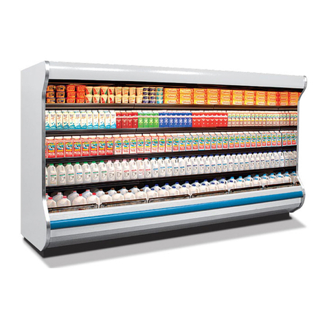
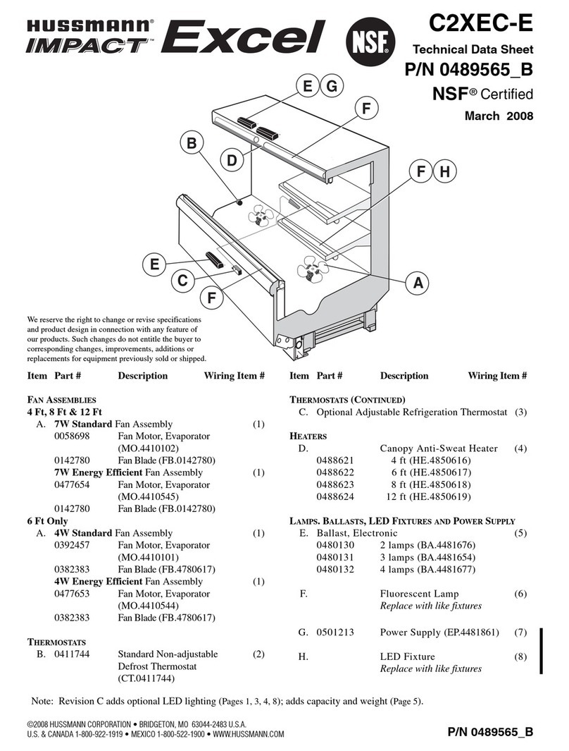
  9. Hussmann IMPACT Elite E2V User manual

Hussmann IMPACT Elite E2V User manual

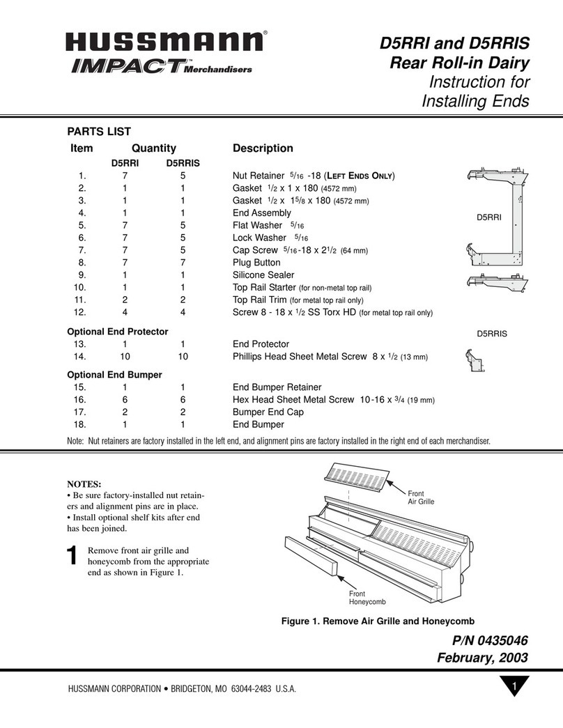
JOINING
JOINING KIT
KIT
NOTE: Be sure merchandisers
have been leveled according to
the installation instructions.
Carefully unpack and inspect the
Joining Kit, making sure there is
no
breakage or damage.
HUSSMANN CORPORATION • BRIDGETON, MO 63044-2483 (Printed in U.S.A.)
®
Vertical Glass
Service Merchandisers
Joining Instruction
Fresh Meat, Deli and Fish Merchandiser
June, 2001
P/N 0430502
1
PARTS LIST
Item Quantity Description
No.
1. 3 Alignment Pin
2. 1 Gasket 1/2x 15/8x 180
3. 1 Gasket 1/2x 1/2x 120
4. 1 Silicone
5. 1 Top Gasket Pad
6. 1 Front Gasket Pad
7. 1 Rear Sill Joining Bracket
8. 4 Washer Head Machine Screws 10-24 x 1/2
9. 1 Cap Screw 5/16 -18 x 11/4
10. 2 Flat Washer 5/16
11. 1 Lock Washer 5/16
12. 1 Hex Nut 5/16 - 18
13. 4 Spacer
14. 2 Cap Screw 5/16 - 18 x 31/2
15. 4 FlatWasher 5/16
16. 2 LockWasher 5/16
17. 2 Hex Nut 5/16 - 18
18. 1 Cap Screw 5/16 - 18 x 3
19. 2 Flat Washer 5/16
20. 1 Lock Washer 5/16
21. 1 Hex Nut 5/16 - 18
22. 4 Cap Plug
23. 1 Interior Trim
24. 1 Exterior Trim
25. 1 Bottom Joint Cover
26. 1 Splashguard Joint Support
27. 4 Hex Head Sheet metal Screw #8 x 1/2
Front
Rear
Top
DO NOT remove rider
until case is in its final position.
CAUTION
!
Cross-Members
Screws
(each leg)
Sides
Leg
Screws
(two each end
of each
cross-member)
Shipping Rider
for 8 ft Case
1Remove items below:
A.
Shelves if installed,
B.
Display Pans,
C.
Rear Pan Bracket and
Upright,
D. Rear Panel and Discharge
Grille,
E. Front Return Air Grille
from case. See Figure 1.
HUSSMANN CORPORATION •BRIDGETON, MO 63044-2483 (Printed in U.S.A.)
2
®
Figure 1. Removing Items from Case
P/N 0430502
A
B
C
D
E
Removing Items from the Case:
2Apply 1 5/8in. (41 mm)
Gasket (Item – 2) to rear
foam panel of both cases as
shown. Check to be sure that
there are no gaps between
gasket and merchandiser.
NNOOTTEE::THIS IS THE ONLY GASKET
THAT IS APPLIED TO BOTH CASES.
THE FOLLOWING STEPS MUST BE
DONE TO ONE CASE ONLY.
SEE FIGURE 3, DETAIL A.
3Apply 1/2in. (13 mm) Gasket
(Item – 3) to the horizontal
recess across the bottom and
on the edge of the glass.
See Figure 3, Detail A.
•Do not stretch gasket, espe-
cially around corners.
•Do not butt gaskets; always
overlap them as shown.
•Remove paper backing after
gasket has been applied.
HUSSMANN CORPORATION •BRIDGETON, MO 63044-2483 (Printed in U.S.A.) 3
Figure 3. Applying 1 5/8in. and 1/2in. Gaskets to the Merchandiser
Figure 2. Checking Alignment Pins
Vertical Glass Service Merchandisers Joining Instruction P/N 0430502
2
3
Apply 1 5/8in. (41 mm) gasket to both cases.
Gasket
Make sure the Alignment Pins (Item – 1) in the front near the
bumpers and at top front are in place before gasketing and
sealing cases. See Figures 2 and 3.
IMPORTANT
Installing Gaskets:
Alignment Pins
DETAIL A.
2
1
1
Alignment Pin
HUSSMANN CORPORATION •BRIDGETON, MO 63044-2483 (Printed in U.S.A.)
4
®
P/N 0430502
AAppppllyyiinnggSSiilliiccoonnee
4Before joining, lay a 1/2in. bead
of clear Silicone (Item – 4)
along the perimeter of the case
as shown in Figure 4.
5
In addition, apply silicone
around the perimeter of
the front box bracket
and over a portion of
the frame as shown in
Figure 4, Details B and
C.
Figure 4. Applying Silicone
4
DETAIL C.
DETAIL B.
4
4
HUSSMANN CORPORATION •BRIDGETON, MO 63044-2483 (Printed in U.S.A.) 5
AAppppllyyiinnggTTooppaanndd
FFrroonnttGGaasskkeettPPaaddss
6Install the Top Gasket Pad,
(Item – 5) over the silicone
applied in previous step.
See Figure 5, Detail D.
7Install the Front Gasket Pad,
(Item – 6) over silicone
applied in previous step.
See Detail E.
8Apply Silicone (Item – 4)
onto the Top Gasket Pad
(Item – 5) and the Front
Gasket Pad (Item – 6).
See Details Fand G.
Top Gasket Pad
Front Gasket Pad
1/2 (13 mm) X 1/2 (13 mm)
1/2 (13 mm) X 1 5/8 in. (41 mm)
2
3
5
4
4
64
Silicone
4
Front
Gasket
Pad 6
Figure 5. Applying Top and Front Gasket Pads
Top
Gasket
Pad
DETAIL G.
DETAIL D.
DETAIL E.
P/N 0430502
5
DETAIL F.
Silicone 4
Vertical Glass Service Merchandisers Joining Instruction
6
®
HUSSMANN CORPORATION •BRIDGETON, MO 63044-2483 (Printed in U.S.A.)
Figure 6. Leveling Merchandisers
9Move the second merchandiser
into position against the first.
Match the alignment pins
with the corresponding holes.
See Figure 6, Details H and I.
10The complete lineup must
be leveled to the highest
point of the floor. After the
first merchandiser has been
set, position the second so
the end frames touch.
A. Set a long level (4 foot or
more) on the upper front panel
of the merchandisers. Adjust
case height by rotating the
Adjustable Leg Leveler until
the merchandisers are flush
and level.
See Figure 6, Detail J.
B. Also check each joint area
to be sure that the panels of
adjoining merchandisers are
flush to each other.
Levels on Upper
Front Panel
MINIMUM
HEIGHT
MAXIMUM
HEIGHT
Adjustable
Leg Leveler
Lower
Raise
Alignment Pins
DETAIL I. DETAIL J.
Levels on Upper
Front Panel
P/N 0430502
CASE 1 CASE 2
DETAIL H.
Top
Alignment
Pin
11Follow the sequence
correctly when bolting the
cases together. See Figure
7, Detail K.
12 Fasten the fronts together
using Cap Screws (Item – 9),
Flat Washers (Item – 10),
LockWashers (Item – 11),
Hex Nut (Item – 12) and
Cap Plug (Item – 22).
See Figure 7, Sequence A.
HUSSMANN CORPORATION •BRIDGETON, MO 63044-2483 (Printed in U.S.A.)
P/N 0430502
Vertical Glass Service Merchandisers Joining Instruction
Figure 7. Overview of Fastener Locations
18
19
19 20 19
21
22
Cap
Plug
C
9
10
11
12
22 A
Cap
Plug
17
15
13
15
14
22
B
Cap
Plug
Spacer
16
Top Alignment
Pin
7
C.
A. B.
Note: Make sure that no more than
(2) threads are exposed when the
cases are bolted together. If this does
occur, the bolt should be shortened,
replaced with a shorter bolt or capped
off according to NSF specifications.
DETAIL K.
HUSSMANN CORPORATION •BRIDGETON, MO 63044-2483 (Printed in U.S.A.)
8
®
13Fasten the rear of the cases
together at two locations
shown below using,
Spacer (Item –13),
Cap Screws (Item –14),
Flat Washers (Item –15),
Lock Washers (Item –16),
Hex Nut (Item –17) and
Cap Plug (Item –22).
See Figure 8, Detail L.
Figure 8. Fastening Rear of Cases Together (Sequence B)
Use caution when installing
fasteners around wiring or
refrigeration lines inside of
struts.
WARNING
!
DETAIL L.
P/N 0430502
RH End of Case
from Front
Electrical Wires
always here
LH End of Case
from Front
Copper Tubing inside
encasement only
on gravity models
otherwise empty
Nut
17
Spacer Spacer
Hex Head
Cap Screw
Lock
Washer
Flat
Washer
CASE
ONE CASE
TWO
14
13
15
16
Flat
Washer
15
13
22
Cap Plug
16 Lock
Washer
B
Top View of Joined Struts
Strut Joining Location
HUSSMANN CORPORATION •BRIDGETON, MO 63044-2483 (Printed in U.S.A.)
P/N 0430502
15Fasten the top rear of the
cases together using
Cap Screws (Item –18),
Flat Washers (Item –19),
Lock Washers (Item –20)
Hex Nut (Item –21), and
Cap Plug (Item –22).
See Figure 9.
Figure 9. Fastening Top Fronts of Cases Together (Sequence C)
Vertical Glass Service Merchandisers Joining Instruction
CASE
ONE
CASE
TWO
20
18
19
19
21
22
Cap Plug
C
9
10
P/N 0430502
Mhdi
®
16Align the Rear Sill and
attach Joining Bracket
(Item –7) with Washer
Head Machine Screw
(Item –8). See Figure 10.
17Apply a bead of
Silicone (Item –4)
down and into the joint
from the exterior and
interior side of glass next
to the Gasket (Item –2).
See Figure 11 and
Figure 12 on next page.
HUSSMANN CORPORATION •BRIDGETON, MO 63044-2483 (Printed in U.S.A.)
Figure 10. Joining Rear Sill
6
7
Use only specified fasteners.
Longer screws will penetrate
rear sill causing damage.
CAUTION
!
Figure 11. Front Lighting Rail Joining Plate
Joining
Plate
Rear
Sill
Gasket
Silicone
Exterior Silicone
Interior
2
4
8
7
10-24 x 1/2
Machine Screw
HUSSMANN CORPORATION •BRIDGETON, MO 63044-2483 (Printed in U.S.A.) 11
P/N 0430502
Adding Trim to the
Joint and Front Glass
18While the silicone is still wet,
insert the Interior and
Exterior Trim (Items –23
and 24) into the silicone that
was applied in Step 17.
Apply tape over the trims to
hold them in place as the
silicone dries for 24 hours.
See Figure 12,
Details M, N and O for
this procedure.
Figure 12. Sealing and adding trim to the Front Joint of Case
Gasket
Exterior
Trim Interior
Trim (Shorter)
Silicone
Silicone
Glass
Glass
Tape
Tape
CASE 1
CASE 1
CASE 2
CASE 2
Detail M.
Detail N.
Detail O.
Add silicone to both interior and
exterior of glass next to the gasket
Note: Cases are shown apart for
clarity of trim and location
Push trim into silicone Cover trim with tape
24
4
4
223
Vertical Glass Service Merchandisers Joining Instruction
HUSSMANN CORPORATION •BRIDGETON, MO 63044-2483 (Printed in U.S.A.)
12
®
P/N 0430502
Figure 13. Installing and Sealing Joint Cover
SEALING THE INTERIOR
BOTTOM OF THE CASE
19Apply a continuous bead
of Silicone (Item –4) to the
joint. Apply a continuous
bead of silicone to each bot-
tom. Press Bottom Joint
Cover (Item –25) over
both cases.
Also apply silicone over
each end of the Joint Cover.
See Figure 13.
Bottom
Joint
Cover
Case
Bottom
Case
Bottom
Joint
Silicone
Joint
Cover
End
Joint Cover
End
25
HUSSMANN CORPORATION •BRIDGETON, MO 63044-2483 (Printed in U.S.A.)
P/N 0430502
SEALING THE EXTERIOR
OF THE CASE
20Apply a smooth continuous
bead of silicone over the
Exterior Top Joint of the
cases.
See Figure 14, Detail P.
21Continue sealing down the
Rear Mullion Joint of the
cases and finally seal the
Rear Sill Joints, as shown in
Figure 14, Details Q &R.
Vertical Glass Service Merchandisers Joining Instruction
Figure 14. Sealing Case Joints
P.
Q.
R.
13
14
P/N 0430502
®
HUSSMANN CORPORATION •BRIDGETON, MO 63044-2483 (Printed in U.S.A.)
22Install the Splashguard
Joint Support (Item –26)
to the splashguard retainer
using Screws (Item –27).
See Figure 15.
Figure 15. Installing the Splashguard Joining Bracket and Splashguard
Splashguard
Splashguard
Retainer
26
27
HUSSMANN CORPORATION •BRIDGETON, MO 63044-2483 (Printed in U.S.A.)
P/N 0430502
23TOINSTALL BUMPERS:
A. Starting from left end of line-
up, insert 2 foot (610 mm)
starter bumper into the front
Top Bumper Retainer. Swing
Bumper down into position
until it “snaps” into place on
the bottom of the retainer.
B. Install full length bumper to
overlap merchandiser joint.
Slide toward left, closing all
gaps. Repeat for rest of line-
up.
C. Use a miter box and fine
toothed saw to cut last full-
length bumper.
See Figures 16 and 17.
24Re-install all items that
were removed in Step 1.
Retainer
2 Foot (610mm) Starter Bumper
Full Length Bumper 2 Foot (610mm) Starter Bumper
Full Length Bumper
Figure 16. Installing Impact Bumper
Figure 17. Installing and offsetting Bumpers
Vertical Glass Service Merchandisers Joining Instruction
Bumper
Bumper
Retainer "Snap"
Bumper
Miter Box
15

Other manuals for IMPACT Elite E2V

1

This manual suits for next models

4

Other Hussmann Merchandiser manuals

Hussmann D5NX-E Instruction Manual

Hussmann

Hussmann D5NX-E Instruction Manual

Hussmann Q3-BC Instruction Manual

Hussmann

Hussmann Q3-BC Instruction Manual

Hussmann RGSSFP Original operating instructions

Hussmann

Hussmann RGSSFP Original operating instructions

Hussmann IMPACT D5R User manual

Hussmann

Hussmann IMPACT D5R User manual

Hussmann GC User manual

Hussmann

Hussmann GC User manual

Hussmann RI2N Instruction Manual

Hussmann

Hussmann RI2N Instruction Manual

Hussmann M3NX-GEP Instruction Manual

Hussmann

Hussmann M3NX-GEP Instruction Manual

Hussmann GGSM Quick guide

Hussmann

Hussmann GGSM Quick guide

Hussmann FMSS Instruction Manual

Hussmann

Hussmann FMSS Instruction Manual

Hussmann IMPACT Elite E4 User manual

Hussmann

Hussmann IMPACT Elite E4 User manual

Hussmann CIDM-I Operating instructions

Hussmann

Hussmann CIDM-I Operating instructions

Hussmann RI2-E Instruction Manual

Hussmann

Hussmann RI2-E Instruction Manual

Hussmann IMPACT Elite E3-XC User manual

Hussmann

Hussmann IMPACT Elite E3-XC User manual

Hussmann MicroSC ISMGG2DA-A User manual

Hussmann

Hussmann MicroSC ISMGG2DA-A User manual

Hussmann IMPACT LWUG Instruction Manual

Hussmann

Hussmann IMPACT LWUG Instruction Manual

Hussmann ARV-570 User manual

Hussmann

Hussmann ARV-570 User manual

Hussmann RCD Operating instructions

Hussmann

Hussmann RCD Operating instructions

Hussmann Impact PWWSP49 Instruction Manual

Hussmann

Hussmann Impact PWWSP49 Instruction Manual

Hussmann RDI Instruction Manual

Hussmann

Hussmann RDI Instruction Manual

Hussmann IMPACT EDS1 Instruction Manual

Hussmann

Hussmann IMPACT EDS1 Instruction Manual

Hussmann Impact Excel M5X-GE Instruction Manual

Hussmann

Hussmann Impact Excel M5X-GE Instruction Manual

Hussmann CWI-6 Quick guide

Hussmann

Hussmann CWI-6 Quick guide

Hussmann IMPACT LWUGH Instruction Manual

Hussmann

Hussmann IMPACT LWUGH Instruction Manual

Hussmann RCD Instruction Manual

Hussmann

Hussmann RCD Instruction Manual

Popular Merchandiser manuals by other brands
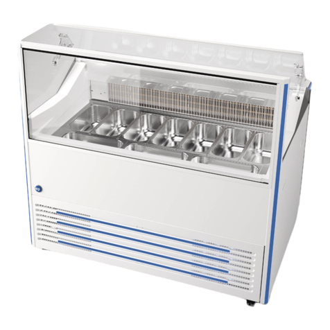
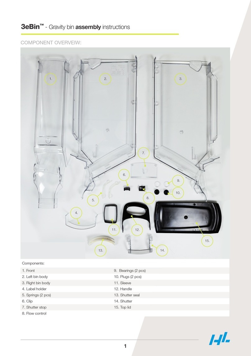
HL Display 3eBin Assembly instructions

HL Display

HL Display 3eBin Assembly instructions

True GDM-23FC-RF Specifications

True

True GDM-23FC-RF Specifications

Crane BevMAX Refresh 6 Media Operation guide
Crane

Crane BevMAX Refresh 6 Media Operation guide
Summit SCR486L owner's manual

Summit

Summit SCR486L owner's manual

True GDM-3 installation manual

True

True GDM-3 installation manual

Randell PH120E2 Operator's manual

Randell

Randell PH120E2 Operator's manual

Master Bilt HOAM Series Installation, operation and maintenance instructions

Master Bilt

Master Bilt HOAM Series Installation, operation and maintenance instructions

Arktic 233238 v.02 user manual

Arktic

Arktic 233238 v.02 user manual

Hatco FLAV-R-SAVOR FSHC-6W1 Installation and operating manual

Hatco

Hatco FLAV-R-SAVOR FSHC-6W1 Installation and operating manual

True GDIM installation manual

True

True GDIM installation manual

Hatco FLAV-R-SAVOR FSD-1 Replacement parts list

Hatco

Hatco FLAV-R-SAVOR FSD-1 Replacement parts list

Carrier Miracool 1300L owner's manual

Carrier

Carrier Miracool 1300L owner's manual

Symbol PTC-960L user guide

Symbol

Symbol PTC-960L user guide

Fusion 20-95651 user manual

Fusion

Fusion 20-95651 user manual

Howard McCray R-CDS40E-12 Specifications

Howard McCray

Howard McCray R-CDS40E-12 Specifications

APW Wyott Racer DMXD-30H Specifications

APW Wyott

APW Wyott Racer DMXD-30H Specifications

Bonnet Neve SkySpace User instructions

Bonnet Neve

Bonnet Neve SkySpace User instructions

Hatco Glo-Ray GRDW-2 Installation & operating manual

Hatco

Hatco Glo-Ray GRDW-2 Installation & operating manual

manuals.online logo
manuals.online logoBrands
  • About & Mission
  • Contact us
  • Privacy Policy
  • Terms and Conditions

Copyright 2025 Manuals.Online. All Rights Reserved.