HVAC Partners EHC09AKCN User manual

482 01 2231 02 4/27/15
Specifications are subject to change without notice
INSTALLATION INSTRUCTIONS
ELECTRIC HEAT ACCESSORY
EHC09AKCN, EHC15AKF, EHC15AKB, EHC20AKF, EHC20AKB,
EHC25AHCF, EHC30AHCF
DANGER, WARNING, CAUTION, and NOTE
The signal words DANGER, WARNING, CAUTION, and NOTE
are used to identify levels of hazard seriousness. The signal
word DANGER is only used on product labels to signify an im-
mediate hazard. The signal words WARNING, CAUTION, and
NOTE will be used on product labels and throughout this manual
and other manuals that may apply to the product.
DANGER −Immediate hazards which will result in severe per-
sonal injury or death.
WARNING −Hazards or unsafe practices which could result in
severe personal injury or death.
CAUTION −Hazards or unsafe practices which may result in
minor personal injury or product or property damage.
NOTE −Used to highlight suggestions which will result in en-
hanced installation, reliability, or operation.
Signal Words in Manuals
The signal word WARNING is used throughout this manu-
al in the following manner:
The signal word CAUTION is used throughout this manu-
al in the following manner:
Signal Words on Product Labeling
Signal words are used in combination with colors and/or
pictures on product labels.
WARNING
Safety Labeling and Signal Words
!
CAUTION
WARNING
!
ELECTRICAL SHOCK HAZARD.
Failure to follow this warning could result in
death and/or personal injury.
Installation or repairs made by unqualified persons
can result in hazards to you and others. Installation
must conform with local building codes or, in the
absence of local codes, with National Electrical Code
ANSI/NFPA 70−1996 or current edition.
The information contained in this manual is intended
for use by a qualified service technician familiar with
safety procedures and equipped with the proper
tools and test instruments.
Shut OFF electric power at unit disconnect and/or
service panel before beginning the following proce-
dures.
!WARNING
USE
EHC heater kits are designed for use with the Observert
Communicating Wall Control and FCM4X communicating fan coil.
When used with the Observer communicating system the electric
heater will be automatically recognized and the airflow will be
configured automatically.
INSTALLATION
INSTALL ELECTRIC HEATER ASSEMBLY
NOTE: Ensure heater coils are not deformed or damaged during
heater installation.
1. Make sure power to unit is off.
2. Remove blower access panel of fan coil unit.
UNIT DAMAGE HAZARD.
Failure to follow this caution may result in property
damage.
Before installation of heater, the black and yellow
pigtail leads must be removed from the fan coil board
or wire harness to prevent possible damage to the
product. Electrical power will be provided to the
board through the heater circuit plug.
!CAUTION
3. Disconnect 2 power wires (black and yellow pigtail leads) from
fan control board or wire harness (if applicable) and discard.
Wires may be part of a plug assembly or attached to terminals
L1 and L2. Remove cooling control plate from fan coil (if
equipped). For 24kW, and 30kW heaters, remove adapter plate.
(See Figure 1)
4. Insert heater assembly into front of fan coil so that element rods
engage holes in rear heat shield.
5. Attach heater control plate to fan coil using 2 screws provided.
For 24kW, and 30kW heater models, attach front of heater to fan
deck using third screw. (See Figure 1)

482 01 2231 02 2
Specifications are subject to change without notice
Figure 1 Installing The Electric Heat Accessory
Table 1 −Accessory Heater Usage
Part Number Description Use with Model Sizes
EHC09AKCN3 9 kW, single phase, no internal circuit protection ALL
EHC15AKF3* 15 kW, single phase, with fuses ALL
EHC15AKB3*† 15 kW, single phase, with circuit breakers ALL
EHC20AKF3* 20 kW, single phase, with fuses ALL
EHC20AKB3*† 20 kW, single phase, with circuit breakers ALL
EHC25AHCF3 24 kW, supplied as 3 phase, field convertible to single phase, with fuses 48 −60
EHC30AHCF3 30 kW, supplied as 3 phase, field convertible to single phase, with circuit breakers 48 −60
† EHC15AKB3 & EHC20AKB3 are not approved for use in Canada (must use fused heaters and certified single point wiring kit).
* 15kW & 20kW are not recommended for specific heat pump applications, see AIRFLOW DELIVERY (CFM)
HEAT PUMP MINIMUM CFM WHEN USING ELECTRIC HEAT (CFM)
FCM
Model Size
Outdoor
Unit Size
Heater Size kW
9 15 20 24, 30
24
18 625 −− −− −−
24 725 875 −− −−
30 875 875 1040 −−
36 970 970 1040 −−
36
24 875 −− −− −−
30 875 1100 1150 −−
36 975 1100 1225 −−
42 1125 1125 1225 −−
48
30 875 875 1150 −−
36 975 1100 1225 −−
42 1125 1125 1225 −−
48 1305 1305 1305 1400
60
36 1100 1350 1350 −−
42 1125 1350 1350 −−
48 1300 1350 1465 1750
60 1625 1625 1750 1750
A/C MINIMUM CFM WHEN USING ELECTRIC HEAT (CFM)
FCM
Model Size
Heater Size kW
9 15 20 24, 30
24
Heater Only
625 725 875 −−
36 700 850 1050 −−
48 700 850 1050 1400
60 1050 1050 1050 1750
NOTES:
1. Heater Only−Air conditioner with electric heater application.
2. These airflows are minimum acceptable airflows as UL listed. Actual airflow delivered will be per airflow delivery chart for Electric Heating
Modes.

482 01 2231 02
3Specifications are subject to change without notice
ATTACH FUSE BOX OR CIRCUIT BREAKER BOX
1. For 15kW and 20kW fused models:
After installing heater assembly, attach fuse assembly to side of
fan coil unit by inserting fuse box tab between insulation and to
left side of unit and fan deck. Mount front of assembly to side
flange with two (2) screws provided. On fan coil units size 4200
and larger, remove wire tie that shortens wire length between
heater and fuses. Fuse cover is closed by engaging dimples in
fuse box. (See Figure 2)
2. For 24kW and 30kW fused models:
Fuse assembly is mounted on heater. Be sure fuse cover is
closed by engaging clip latch on unit top panel. (See Figure 1)
ELECTRICAL SHOCK.
Failure to follow this warning could result in death and/or
personal injury.
Close fuse box before power is turned to ON position.
!WARNING
3. For 5kW through 20kW circuit breaker models:
After installing heater assembly, attach circuit breaker assembly
to unit with screws provided. (See Figure. 3) On fan coil units
size 4200 and larger, remove wire tie that shortens wire length
between heater and circuit breaker assembly to allow mounting
of circuit breaker assembly. (See Figure 3)
4. Circuit breaker models require installing a bezel in unit door to
provide safe access to circuit breakers. Bezel mounts on inside
of blower door. (See Figure 4)
Figure 2 Fused Model Installation
a. Cut insulation away from access hole in blower access panel.
Slide bezel flanges under insulation. Lip on bezel must protrude
inward toward unit.
b. Secure bezel to panel with two (2) No. 6 hex head screws. Insert
screws through original cover plate holes on access panel and
drive into engagement holes on bezel flanges.
ELECTRICAL CONNECTIONS
Refer to unit instructions for recommended wiring procedures.
Install wiring in accordance with all applicable local and national
codes.
Connect heater wiring harness plug to receptacle on fan control
board or wire harness. A positive connection must be made
between plug and receptacle. Plug will interlock with receptacle
when properly seated. Harness contains both 24V control and
high−voltage wiring. Blower power is provided through heater
harness.
NOTE: Units with or without electric heaters require a minimum
CFM. Refer to unit wiring label to ensure the fan speed selected with
electric heaters is equal to or greater than the minimum fan speed
indicated. The minimum CFM for cooling is determined by the
outdoor unit requirements. Use the higher of the two for year−round
operation.
Figure 3 Circuit Breaker Model Installation
A. Wire 24V Control Systems
1. Connections to unit
Use No. 18 AWG color−coded, insulated (35 Deg. C minimum)
wire to make low−voltage connections between thermostat, fan
coil unit, and outdoor unit. If thermostat is located more than 100
ft. from unit (as measured along the low−voltage wire), use No.
16 AWG color−coded, insulated (35 Deg. C minimum) wire. All
wiring must be separated from line voltage power leads. Refer
to outdoor unit wiring instructions for additional wiring procedure
recommendations.
2. Transformer
Transformer is factory wired for 230V operation. For 208V ap-
plications, disconnect black wire on transformer 230V terminal
and reconnect it to 208V terminal. (See Figure 5) The secondary
circuit of transformer is protected by a 5−amp fuse mounted on
fan control board.
3. Heater staging
The units are shipped circuited for single stage operation and
the Observer Wall Control only supports single stage operation.
4. Rectifier and Time Delay Boards
Each heater element is controlled by a relay mounted on the
heater panel. The relay has a 24V DC coil. Each relay has a
small rectifier board attached directly to relay coil terminals. The
rectifier board converts incoming 24V AC control signal to DC.
Some heaters may have up to three relays. These relays are for
future use with a control capable of staging the electric heat. The
second and/or third relay rectifier board also has a time delay
feature and a small jumper wire built into it. With the jumper un-
cut, the time delay allows the second stage heat to be energized
approximately five (5) seconds after the first stage. On 24kW,

482 01 2231 02 4
Specifications are subject to change without notice
and 30kW heaters, the third stage relay board jumper is cut at
factory. This provides an eight (8) second delay after first stage
relay closes.
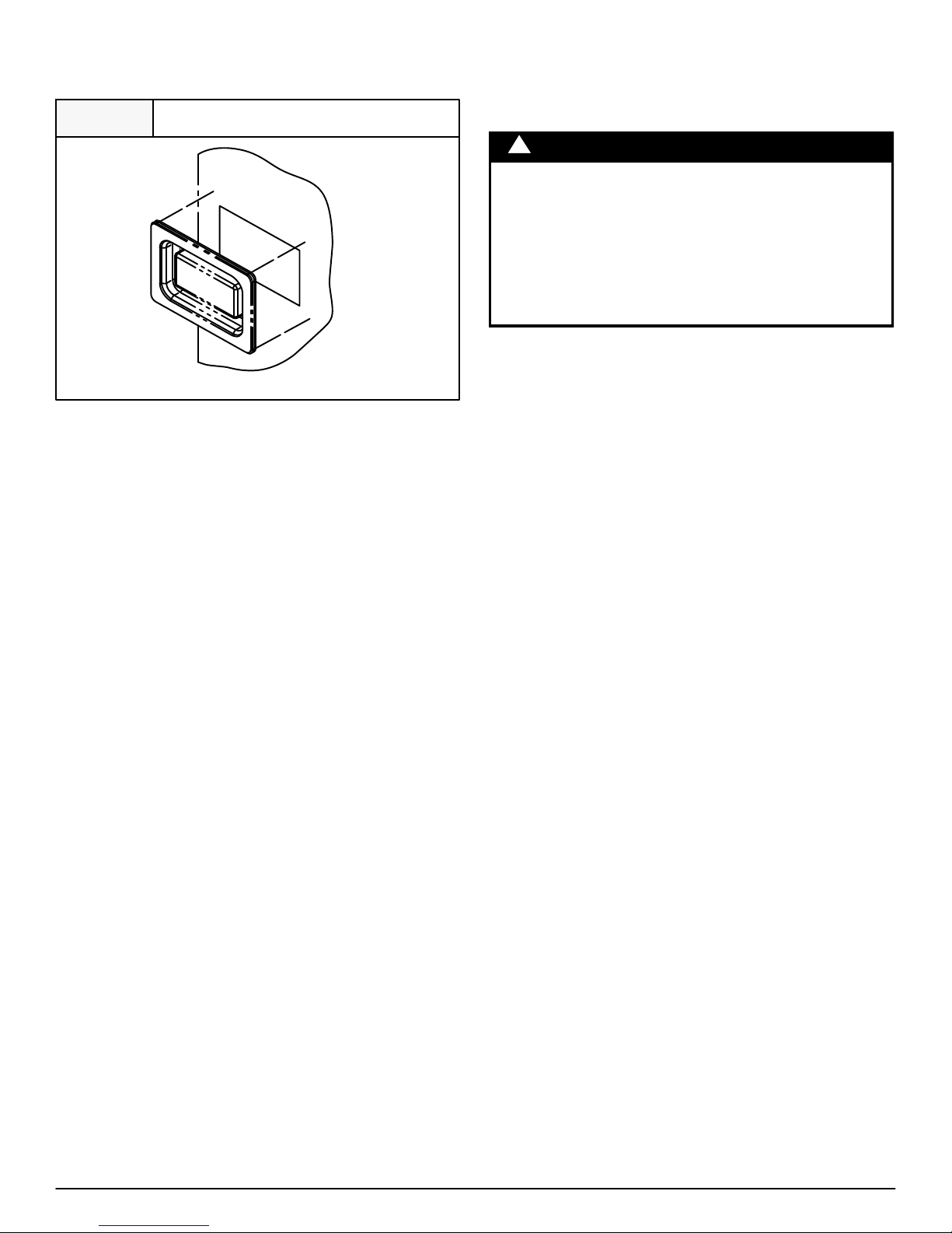
Figure 4 Bezel Installation
A03069
Installation of Window Bezel for Circuit Breaker Model Heater
B. Power Connections
NOTE: Heater supply circuit wire size and overcurrent protection
must comply with National Electrical Code (NEC) and UL branch
circuit requirements. (See Table 3) Wires and overcurrent
protection, integral to the heater, are not required to meet branch
circuit requirements. Internal circuit protection of 60 amps
(maximum) is acceptable.
1. Unprotected heaters: (See Figures 6, 10, and 11)
a. The 9kW single phase and 15kW three phase heaters can be
wired for single supply circuit only. Supply circuit connects to
heater pigtail leads.
b. The 9kW single phase heaters can use a separate field−
installed, factory−authorized disconnect kit which installs in fan
coil.
NOTE: Refer to wiring label for component locations.
c. The 9kW heater is factory wired for single supply circuit, single
phase. To convert heater to single supply circuit, three phase:
(1.) Disconnect blue wire from relay 1 terminal 6. Cut, strip, and
connect to field wire L3.
(2.) Disconnect yellow wire from relay 3 terminal 6 and connect
to relay 1 terminal 6.
(3.) Disconnect blue wire from relay 3, terminal 2, and connect
to relay 3 terminal 6.
2. Circuit breaker heaters: (See Figures 7 and 9)
The 15kW and 20kW heaters can be wired for dual−supply circuits
only.
3. Fused heaters: (See Figures 8, 12, 13, and 14)
a. The 15kW and 20kW heaters can be wired for single or dual
supply circuits. Single supply circuit wiring requires a factory
authorized, single−point adapter kit.
b. The 24kW and 30kW heaters can be wired for single or multiple
supply circuits. Heaters are factory wired for single circuit three
phase. To convert heaters to single circuit single phase, discon-
nect yellow lead from L3 and connect to L1. Disconnect black
lead from L3 and connect to L2. To convert heaters to multiple
supply circuit single phase, remove and discard leads between
single circuit terminal block and fuse block. Remove and discard
single circuit terminal block. Attach L1 through L6 power leads
as indicated on label next to fuse block.
C. Ground Connections
ELECTRICAL SHOCK.
Failure to follow this warning could result in property
damage and/or death.
According to NEC, ANSI/NFPA 70, and local codes,
cabinet must have an uninterrupted or unbroken ground
to minimize personal injury if an electrical fault should
occur. The ground may consist of electrical wire or metal
conduit when installed in accordance with existing
electrical codes. (See Ground/Conduit Note below.)
!WARNING
NOTE: Use UL−listed conduit and conduit connector for connecting
supply wire(s) to unit to obtain proper grounding. If conduit
connection uses reducing washers, a separate ground wire must be
used. Grounding may also be accomplished by using grounding
lugs provided in control box.
1. For unprotected or single circuit heaters, 1 equipment ground
connection is provided on fan coil unit. (See Figure 1 or 2)
2. For 15kW and 20kW circuit breaker heaters, an additional
ground lug is provided on circuit breaker mounting bracket for dual
circuit grounding. (See Figure 3)
3. For 15kW and 20kW fused heaters, an additional ground lug is
provided on fuse mounting bracket for dual circuit grounding. (See
Figure 2)
4. For 24kW and 30kW fused heaters, two (2) additional ground
lugs are provided for single phase, multi circuit wiring. (See Figure
1)
D. FAN SPEED SELECTION
FCM
The FCM fan coil with the Observer Wall Control will automatically
select the appropriate airflow for the selected heater size. Refer to
airflow/CFM tables for airflow delivery.
CONVERSION OF CIRCUIT BREAKER FOR DOWNFLOW
APPLICATIONS
1. Tag and disconnect factory wiring from terminals on circuit
breaker(s).
2. Pull white plastic release tab on the bottom of circuit breaker
straight out to release circuit breaker from bracket. (See Figure 16)
3. Remove quick connect adapters from factory side of breaker(s).
Reinstall adapters on other end of breakers(s). Be sure adapter is
located between lug screw and plate. Torque lug screw to 30−in−.lb.
4. Rotate breaker 180 degrees from its original position and reinstall
in bracket. Slide breaker slot into sheet metal tab and snap breaker
into place. Make sure both tabs engage breaker. Reconnect wiring
on opposite end. Make sure wires are positioned as before.
5. Remount circuit breaker bracket into unit so that the switch will be
in UP position when ON.
ATTACH WIRING DIAGRAM AND RATING LABEL
Attach heater rating label included with kit over existing electrical
information label located on front access panel of fan coil. (See
Figure 17) If kit contains multiple rating labels, ensure correct label
is applied (check phase and supply circuits).
VERIFY INSTALLATION
After completion of heater installation, check wiring to ensure
tightness and that proper connections and routings have been
made. Ensure all electrical covers are in place and proper labels
have been applied. Reinstall blower access panel before turning
unit power on.

482 01 2231 02
5Specifications are subject to change without notice
Figure 5 Connection of Transformer
230
C
208
BRN
RED
YEL
BLK
SECONDARY
PRIMARY
A94067
Figure 6 9 kW Non−fused Heaters
Figure 7 15 and 20 kW Fused Heaters
Figure 8 15 and 20 kW Circuit Breakers
Figure 9
lug
15 kW 3−Phase Heater
Figure 10 24 and 30 kW Heaters

482 01 2231 02 6
Specifications are subject to change without notice
Figure 11 24 and 30 kW Heaters
Figure 12 24 and 30 kW Heaters
Figure 13 Conversion of Circuit Breaker
Figure 14 Heater Rating Label Location

7 482 01 2231 02
Specifications are subject to change without notice
ELECTRIC HEATER ELECTRICAL DATA
Heater Model Heater kW PHASE
INTERNAL
CIRCUIT
PROTECTION
HEATER AMPS
208/230V
BRANCH CIRCUIT
Min Ampacity k
208/230V
Min Wire Size (AWG)
208/230V 1
Min Gnd Wire Size
208/230V
Max Fuse/Ckt Bkr Amps
208/230V
Max Wire Length
208/230V (Ft)‡‡
Single
Circuit
Dual Circuit Single
Circuit
Dual Circuit Single
Circuit
Dual Circuit Single
Circuit
Dual Circuit Single
Circuit
Dual Circuit Single
Circuit
Dual Circuit
230v 208v L1,l2 L3,L4 L1,L2 L3,L4 L1, L2 L3, L4 L1, L2 L3,L4 L1,L2 L3,L4 L1,L2 L3,L4
EHC09AKCN3{9 6.8 1 None 32.8/36.0 — — 49.5/53.5 — — 8/6 — — 10/10 — — 50/60 — — 54/87 — —
9 6.8 3 None 18.8/20.8 — — 32.0/34.5 — — 8/8 — — 10/10 — — 35/35 — — 83/85 — —
EHC15AKF3 15 11.3 1 Fuse 54.2/59.9 36.2/40.0 18.1/20.0 76.3/83.4 53.8/58.5 22.7/25.0 4/4 6/6 10/10 8/8 10/10 10/10 80/90 60/60 25/25 88/89 78/80 75/76
EHC15AKB3 15 11.3 1 Ckt Bkr — 36.2/40.0 18.1/20.0 — 53.8/58.5 22.7/25.0 — 6/6 10/10 — 10/10 10/10 — 60/60 25/25 — 78/80 75/76
EHC20AKF3 20 15.0 1 Fuse 72.3/79.9 36.2/40.0 36.2/40.0 98.9/108.4 53.8/58.5 45.3/50.0 3/2 6/6 8/8 8/6 10/10 10/10 100/110 60/60 50/50 85/109 78/80 59/59
EHC20AKB3 20 15.0 1 Ckt Bkr — 36.2/40.0 36.2/40.0 — 53.8/58.5 45.3/50.0 — 6/6 8/8 — 10/10 10/10 — 60/60 50/50 — 78/80 59/59
EHC25AHCF3}24 18.0 3 Fuse 50.1/55.4 — — 71.2/77.8 — — 4/4 — — 8/8 — — 80/80 — — 94/95 — —
24 18.0 1 Fuse 86.7/95.5 — — 116.9/127.9 — — 1/1 — — 6/6 — — 125/150 — — 115/116 — —
EHC30AHCF3}30 22.5 3 Fuse 62.6/69.2 — — 86.8/95.0 — — 3/3 — — 8/8 — — 90/100 — — 97/98 — —
30 22.5 1 Fuse 109.0/120.0 — — 144.8/158.5 — — 0/00 — — 6/6 — — 150/175 — — 117/150 — —
FIELD MULTIPOINT WIRING OR 24 AND 30 KW SINGLE PHASE
Heater Model
Heater kW
P
H
A
S
E
Heater Amps 208/230V Minimum Circuit Ampacity
208/230V k
Minimum Wire Size (AWG)
208/230V}Min Gnd
Wire Size
208/230V
Max Fuse/Ckt Bkr Amps
208/230V
Max Wire Length 208/230V
(FT)}}
L1, L2 L3, L4 L5, L6 L1, L2 L3, L4 L5, L6 L1, L2 L3, L4 L5, L6 L1, L2 L3, L4 L5, L6 L1, L2 L3, L4 L5, L6
230V 208V
EHC25AHCF3}24 18.0 1 28.9/32.0 28.9/32.0 28.9/32.0 44.7/48.5 36.2/40.0 36.2/40.0 8/8 8/8 8/8 10/10 45/50 40/40 40/40 59/60 73/73 73/73
EHC30AHCF3}30 22.5 1 36.2/40.0 36.2/40.0 36.2/40.0 53.8/58.5 45.3/50.0 45.3/50.0 6/6 8/8 8/8 10/10 60/60 50/50 50/50 78/80 59/59 59/59
Notes:
1Copper wire must be used. If other than uncoated (non−plated), 75°C ambient, copper wire (solid wire for 10 AWG and smaller, stranded wire for larger than 10 AWG) is used,
consult applicable tables of the National Electric Code (ANSI/NFPA 70).
kIncludes blower motor amps of largest Fan Coil used with heater.
{Supplied as single phase, field convertible to 3−phase.
}Supplied as 3−phase, field convertible to single phase, single or multiple supply circuits.
}} Length shown is as measured one way along wire path between unit and service panel for a voltage drop not to exceed 2%.

482 01 2231 02
8Specifications are subject to change without notice
WIRING DIAGRAM FOR HEAT ACCESSORIES
EHC09AKCN (Field Convertible to three phase.)
N = NON−FUSED
EHC15AKF/B
F = FUSED, B = CIRCUIT BREAKER

482 01 2231 02 9
Specifications are subject to change without notice
WIRING DIAGRAM FOR HEAT ACCESSORIES
EHC20AKF/B
F = FUSED, B = CIRCUIT BREAKER
EHC25AHCF, EHC30AHCF (Shipped three phase, see below.)
F = FUSED

482 01 2231 02
10 Specifications are subject to change without notice
WIRING DIAGRAM FOR HEAT ACCESSORIES
EHC25AHCF, EHC30AHCF (Field Converted to single phase, see below.)
F = FUSED
Copyright 2015 International Comfort Products
Lewisburg, Tennessee 37091 USA
This manual suits for next models
6
Table of contents
Popular Electric Heater manuals by other brands

Creda
Creda Heating Solution brochure

Airflow
Airflow SunShine Threesome 6500A Installation Instructions and Warranty

Harvia
Harvia Virta Instructions for installation and use

Nibe
Nibe ELK 42 Installation and maintenance instructions

Harvia
Harvia TRC70EE Instructions for installation and use

Cadet
Cadet The Com-Pak Plus owner's guide

Bromic Heating
Bromic Heating Tungsten 2000W Installation, instruction and service manual

DeLonghi
DeLonghi HVR 9032 instruction manual

IKI
IKI Pillar IKI 4,5 kW Instructions for installation and use

Holmes
Holmes HFH436WGL owner's guide

Kiwi
Kiwi kht-8417 instruction manual

Space-Ray
Space-Ray LTU 160/100-N7 Installation and operation instructions