MP24.9731
09JUL09
SECTION II
625/625S SERIES LEVELING SYSTEMS
COMPONENT INSTALLATION
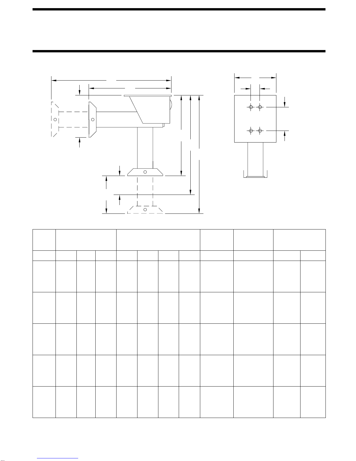
Vehicles with spring suspensions. The ground clearances listed in the Dimension Charts apply to vehicles with a
full load of fuel, water and equipment. If the vehicle is empty, typically 1 inch should be added to the listed dimensions. Also,
if the vehicle is new, the vehicle may settle down 3/4 of an inch or more in the first year or 10,000 miles.
CLEARANCE TO WORK UNDER THE VEHICLE WITH THE AIR BAGS DEFLATED.
SEVERAL INCHES WHEN THE AIR IS EXHAUSTED FROM THE AIR BAGS. MAKE SURE THERE IS ADEQUATE
VEHICLE IF THE VEHICLE IS SUPPORTED ON THE SUSPENSION AIR BAGS. THE VEHICLE WILL RAPIDLY DROP
DO NOT CRAWL UNDER A VEHICLE WITHOUT PROPERLY SUPPORTING THE FRAME OF THE
WARNING:
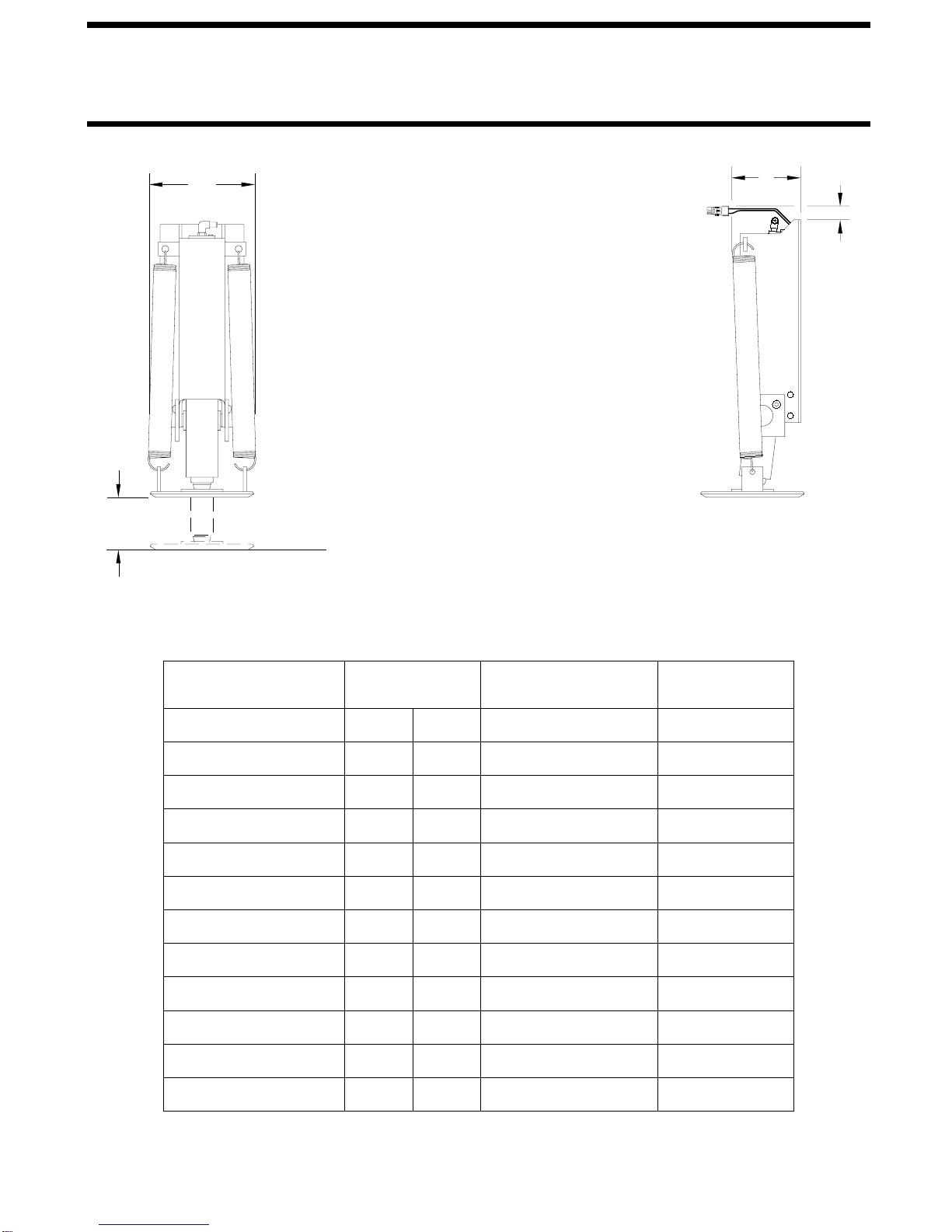
Vehicles with air suspensions. Typically, straight-acting jacks are used on vehicles with an air suspension. If the
vehicle is at normal ride height when mounting heights are set, you must remember the chassis will lower between 2 and 3
inches when the suspension air bags are emptied. Ground clearances listed in the Dimension Charts are typically figured with
the suspension air bags empty. If possible, measure the difference between the bottom of the frame and the ground with the
vehicle at normal ride height and with the air bags empty. Add this dimension to the suggested ground clearance for the jacks
listed in the dimension charts. Example: A 13 inch stroke jack is typically mounted with 7 to 9 inches of ground clearance. A
vehicle with an air suspension drops 3 inches from normal ride height when the suspension air bags are emptied. The typical
ground clearance for this installation should be 10 to 12 inches with the vehicle at normal ride height.
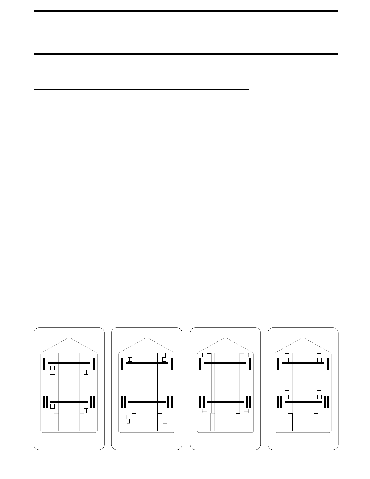
The following are some general rules to follow for a typical installation of leveling jacks on a vehicle:
1.) The front and rear jacks should be mounted behind the front and rear axles as close to the axles as possible. Jacks are not
typically mounted in front of either the front or rear axles.
2.) The rear jacks are not typically mounted behind the end of the main frame rails on frame rail extensions.
3.) If the vehicle is equipped with a tag axle, the rear jacks are typically mounted between the drive axle and the tag axle.
4.) Front or rear jacks may be staggered several inches to accommodate vehicle equipment and compartments. If a cross tie is
required, staggering the jacks more than an inch or two may not be possible.
5.) Most mounting brackets and straight-acting jack pivot brackets are designed with specific mounting hole arrangements.
Some brackets are designed with a flange or finger that bolts to the bottom flange of the frame rail. When a mounting
bracket or pivot bracket has a specific mounting hole arrangement, use of all bolt holes, including the flange holes is
important. When mounting brackets or pivot brackets have multiple hole arrangements, the widest possible set of
holes should be used. Always bolt brackets as close to the top and bottom of the frame rail as the brackets allow.
6.) Jacks and/or mounting brackets must be mounted so they do not interfere with suspension components, springs, air bags,
linkages, etc. when retracted or extended.
7.) Front jacks and/or mounting brackets must be mounted so they do not interfere with the front tires when the tires are turned
from stop to stop. Remember as a vehicle moves up and down, the geometry of the suspension can change. Clearance with
the vehicle at rest may change as the vehicle moves up or down.
8.) Jacks should not be exposed to high temperatures such as exhaust components. Heat shields must be installed when
necessary. If heat shields are supplied with jacks or brackets, both sides should be installed. Aftermarket exhaust systems
may be installed at a later date.
9.) Normally, modification of the vehicle exhaust is not needed but if modification is needed, this should be done before the
installation of the leveling jacks.
Welding and drilling frame rails.Typically, HWH mounting brackets and jacks are designed with holes to allow a
bolt on installation. Welding to HWH supplied mounting brackets or a straight-acting jack pivot bracket is allowable but all
acceptable welding practices must be followed.
Before any welding is done on the frame rail, the chassis manufacturer
must be contacted for authorization and procedures.
Refer to WELDING in PART II JACK INSTALLATION for general
welding information. This section contains basic welding information including procedures to follow for several different
frame manufactures.
This information may not be complete and may change from time to time so it is important to
contact the frame manufacturer for current, specific welding information and procedures.
When drilling holes,
do not
drill in the radius of the frame rail,
do not
drill closer than one bolt diameter to the edge of the frame rail flange and
do not
drill next to an existing hole. Again, one bolt diameter distance should be maintained.
As with welding, contact the
frame manufacturer for specific drilling information and procedures.
WHEN DRILLING OR WELDING, ALWAYS
CHECK BEHIND THE OBJECT YOU ARE WELDING OR DRILLING ON FOR OBSTRUCTIONS OR EQUIPMENT SUCH
AS WIRING, HOSES, BATTERIES OR HOLDING / FUEL TANKS. THESE OBJECTS MUST BE PROTECTED FROM
WELDING HEAT OR DRILLING.