Hy-Brid Lifts HB-1230 User manual

MAINTENANCE & TROUBLESHOOTING MANUAL
SELF-PROPELLED AERIAL WORK PLATFORM
SUPO-646
REV A
HB-1230
SERIES I
BY CUSTOM EQUIPMENT LLC

NOTES
If there is a question about application
and/or operation, contact:
Custom Equipment, LLC
2647 Hwy 175
Richfield, WI 53076
U.S.A.
P: +1-262-644-1300
F: +1-262-644-1320
www.hybridlifts.com
MAINTENANCE & TROUBLESHOOTING
HB1230
SUPO646
REV A
2
FOREWORD
Original instructions written in English
The purpose of this Maintenance Manual is to provide qualified service personnel with information for servicing and
maintaining Hy-Brid Lifts. All information in this manual must be read and understood before any attempt is made
to service this machine.
The operation and safety manual is considered a part of the work platform and contains instructions and operating
procedures essential to properly and safely operate the Custom Equipment Hy-Brid Lift. Users must read and
understand all information in the Safety and Operations Manual before operation.
THE OPERATION AND SAFETY MANUAL MUST
BE READ AND UNDERSTOOD PRIOR TO OPERATING THE MACHINE.
• The user/operator should not accept operating responsibility until the manual has been read and understood as
well as having operated the lift under supervision of an experienced and qualified operator.
• Because the manufacturer has no direct control over machine application and operation, proper safety
practices are the responsibility of the user and all operating personnel.
ANY MODIFICATION ON THIS MACHINE WITH
OUT THE EXPRESS WRITTEN CONSENT OF THE MANUFACTURER IS PROHIBITED.
DANGER
WARNING
MAINTENANCE & TROUBLESHOOTING
HB1230
SUPO646
REV A
3

TABLE OF CONTENTS
NOTES.......................................................................................................................................................................................... 2
FOREWORD ................................................................................................................................................................................ 3
TABLE OF CONTENTS............................................................................................................................................................... 4
INDEX OF FIGURES.................................................................................................................................................................... 5
SECTION 1 | SAFETY.................................................................................................................................................................. 6
1.1 | SAFETY SYMBOLS.......................................................................................................................................................................... 6
1.2 | GENERAL RULES AND PRECAUTIONS ................................................................................................................................... 6
1.3 | SAFETY GUIDELINES.................................................................................................................................................................... 7
SECTION 2 | MAINTENANCE ................................................................................................................................................... 8
2.1 | BATTERY MAINTENANCE........................................................................................................................................................... 8
2.2 | CHARGING THE BATTERY.........................................................................................................................................................8
2.3 | LUBRICATION.............................................................................................................................................................................. 10
2.4 | COMPONENTS REQUIRING ADJUSTMENT....................................................................................................................... 10
2.5 | EXAMINATION, REPAIR, REPLACEMENT OF LIMITED LIFE COMPONENTS..............................................................10
2.6 | SAFETY DEVICES AND SYSTEMS REQUIRING CHECKS ............................................................................................... 10
2.7 | STORAGE......................................................................................................................................................................................10
2.8 | MAJOR ALTERATIONS OR REPAIRS...................................................................................................................................... 10
2.9 | OTHER PROCEDURES.............................................................................................................................................................. 10
SECTION 3 | MAINTENANCE CHECKLISTS ..........................................................................................................................11
3.1 | PRESTART INSPECTION CHECKLIST................................................................................................................................... 12
3.2 | MONTHLY INSPECTION CHECKLIST ................................................................................................................................... 13
3.1 | PREDELIVERY/ANNUAL/FREQUENT INSPECTION CHECKLIST................................................................................... 14
SECTION 4 | TECHNICAL REFERENCES .............................................................................................................................. 16
4.1 | HYDRAULIC SCHEMATIC ......................................................................................................................................................... 16
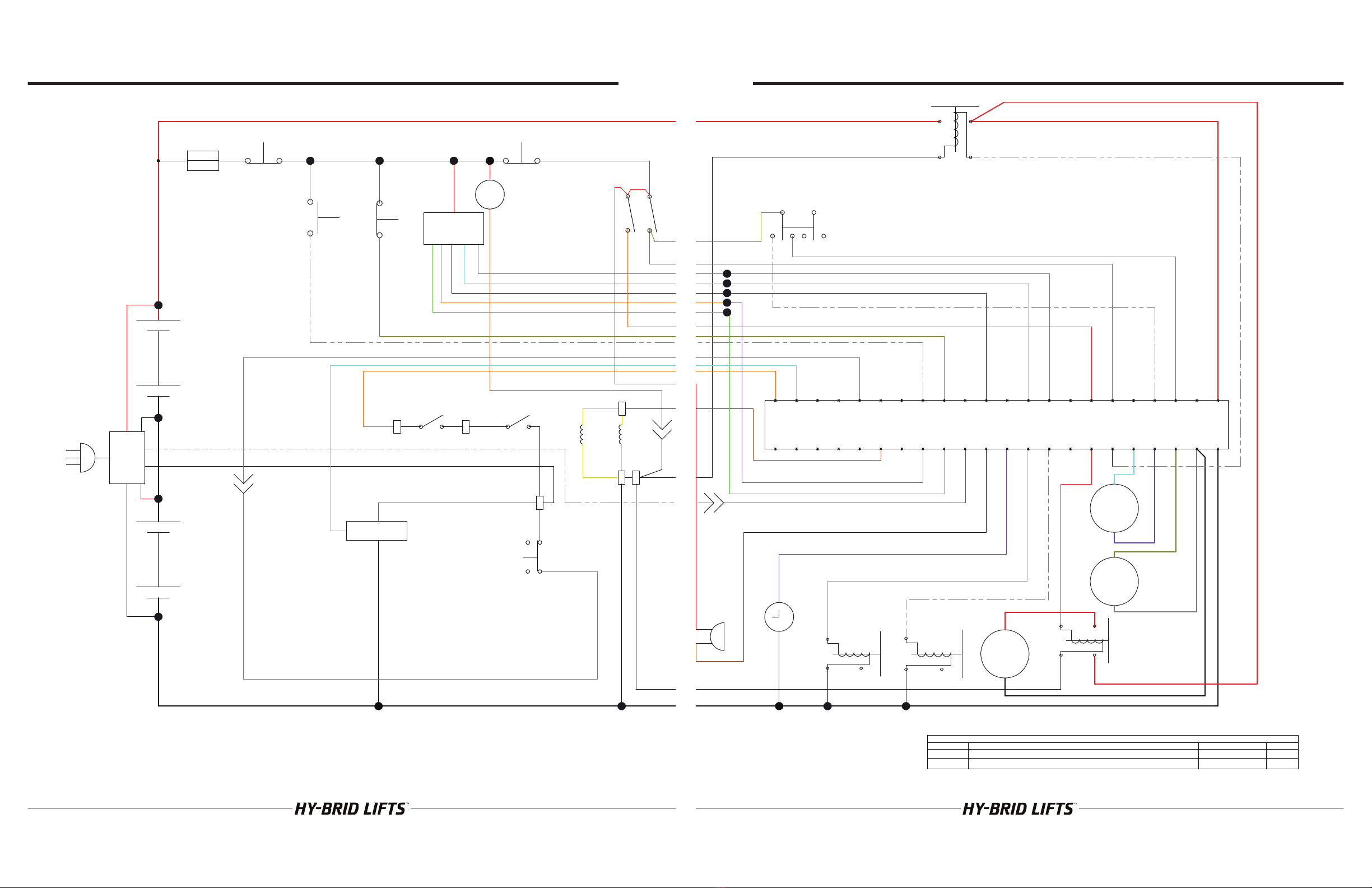
4.2 | ELECTRICAL SCHEMATIC........................................................................................................................................................ 18
4.3 | CONTROL BOARD DIAGNOSTICS........................................................................................................................................20
SECTION 5 | WIRING DIAGRAMS.......................................................................................................................................... 22
5.1 | WIRING DIAGRAM .....................................................................................................................................................................23
5.2 | LOWER CONTROLS WIRING DIAGRAM ..............................................................................................................................24
5.3 | UPPER CONTROLS WIRING DIAGRAM................................................................................................................................26
5.4 | MAIN POWER/SAFETY CIRCUIT.............................................................................................................................................28
5.5 | DRIVE CIRCUIT ...........................................................................................................................................................................30
5.6 | ELEVATE/LOWER CIRCUIT ......................................................................................................................................................32
SECTION 6 | TROUBLESHOOTING FLOWCHARTS ...........................................................................................................34
6.1 | MAIN POWER/SAFETY CIRCUIT.............................................................................................................................................34
6.2 | DRIVE CIRCUIT...........................................................................................................................................................................36
6.3 | ELEVATE CIRCUIT ......................................................................................................................................................................38
6.4 | LOWER CIRCUIT........................................................................................................................................................................ 40
SECTION 7 | PARTS DIAGRAMS.............................................................................................................................................42
7.1 | SAFETY AND CONTROL DECALS...........................................................................................................................................42
7.2 | MAIN POWER/SAFETY CIRCUIT .............................................................................................................................................43
7.3 | DRIVE CIRCUIT............................................................................................................................................................................44
7.4 | ELEVATE / LOWER CIRCUIT ....................................................................................................................................................46
7.5 | COVERS.........................................................................................................................................................................................48
7.6 | RAILINGS.......................................................................................................................................................................................49
SECTION 8 | WARRANTY........................................................................................................................................................50
SECTION 9 | ADDITIONAL RESOURCES .............................................................................................................................. 52
NOTES........................................................................................................................................................................................54
MAINTENANCE & TROUBLESHOOTING
HB1230
SUPO646
REV A
4
Revision Log
Revision A..........................................................................................................................................................................December 2013
INDEX OF FIGURES
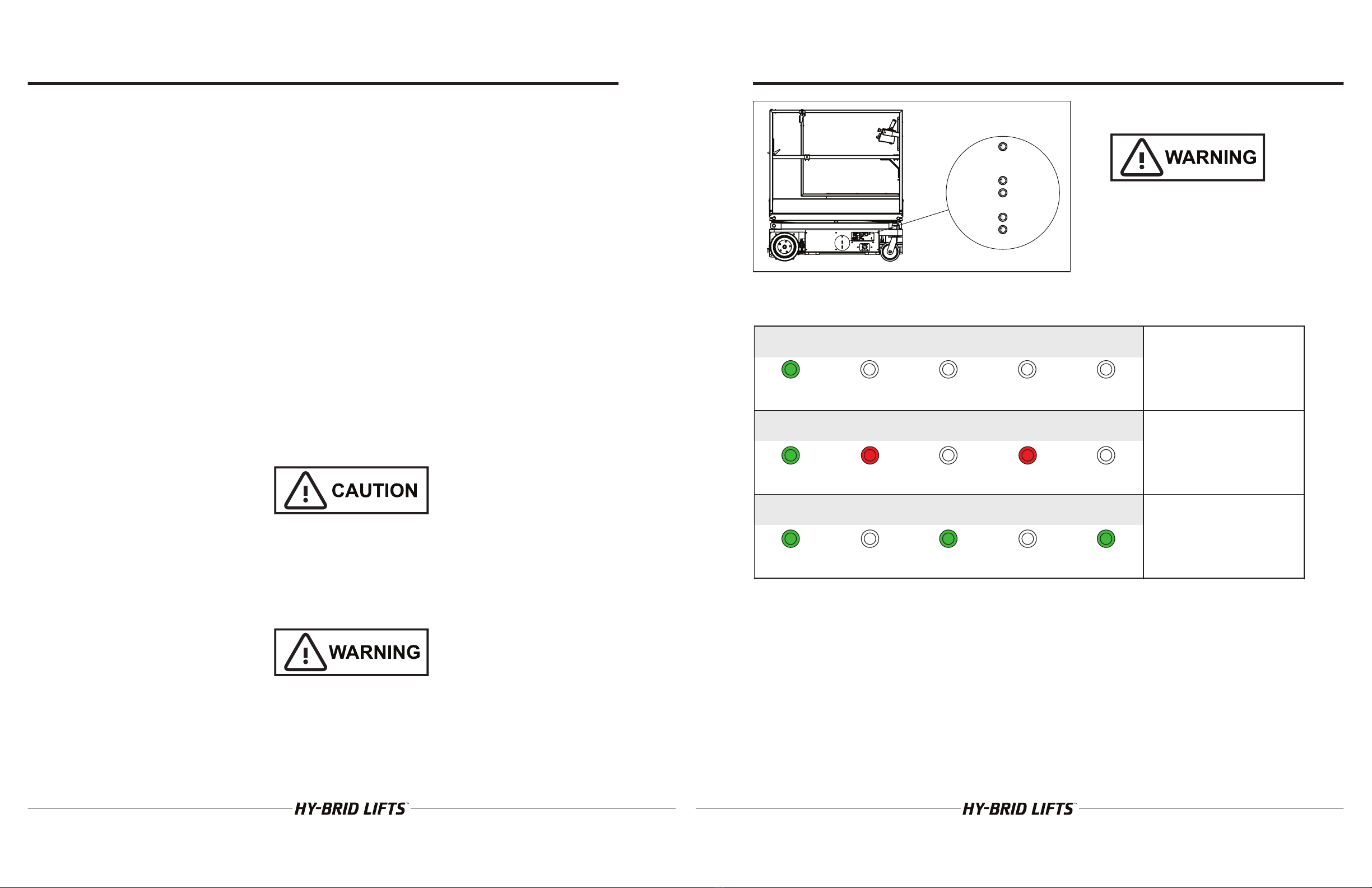
FIGURE 1: Battery Charger LED Display .............................................................................................................................................. 9
MAINTENANCE & TROUBLESHOOTING
HB1230
SUPO646
REV A
5

FAILURE TO FOLLOW THIS WARNING WILL CAUSE
DEATH OR PERSONAL INJURY.
“DANGER” indicates an imminently hazardous situation,
which, if not avoided, will result in death or serious
injury.
FAILURE TO FOLLOW THIS WARNING MAY CAUSE
DEATH OR PERSONAL INJURY.
“WARNING” indicates a potentially hazardous situation,
which, if not avoided, could result in death or serious
injury
FAILURE TO FOLLOW THIS WARNING MAY CAUSE
INJURY OR DAMAGE TO EQUIPMENT.
“CAUTION” indicates a potentially hazardous situation
which, if not avoided, could result in minor or
moderate injury or damage to equipment
CAUTION
DANGER
WARNING
1.1 | SAFETY SYMBOLS
1.2 | GENERAL RULES AND PRECAUTIONS
Custom Equipment, LLC designed the Hy-Brid Lift self-propelled scissors lift to be safe and reliable. It is intended for
elevating personnel, along with their necessary tools and materials to overhead work locations.
An operator of any type of work platform is subject to certain hazards that cannot be protected by mechanical
means. It is therefore essential that operators be competent, careful, physically and mentally fit and thoroughly
trained in safe operation of this machine.
Although Custom Equipment, LLC conforms to specified American National Standards Institute ANSI/SIA A92.6
Standard, it is the responsibility of the owner to instruct operators with the safety requirements made not only by
Custom Equipment, LLC, but by the various safety boards in your area, as well as additional requirements set forth
by ANSI A92.6. If you come across a situation that you think might be unsafe, stop the platform and request further
information from qualified sources before proceeding.
MAINTENANCE INFORMATION IS FOR USE BY TRAINED PERSONNEL ONLY
SECTION 1 | SAFETY
MAINTENANCE & TROUBLESHOOTING
HB1230
SUPO646
REV A
6
SECTION 1 | SAFETY
NEVER REACH BETWEEN SCISSORS LINKS OR PROP UP PLATFORM UNLESS MAINTENANCE PINS ARE IN
PLACE.
1.3 | SAFETY GUIDELINES
Maintenance Lock
The maintenance lock must be placed into position whenever the machine is being serviced in the raised or partially
raised position. Serious injury and/or death could result if maintenance lock is not used properly.
FAILURE TO COMPLY WITH THE LISTED SAFETY PRECAUTIONS MAY RESULT IN MACHINE DAMAGE,
PERSONNEL INJURY, OR DEATH.
Other Guidelines
• Never work under an elevated platform until maintenance locks have been engaged.
• Remove all rings, watches, and jewelry when performing any maintenance.
• Do not wear long hair unrestrained or loose fitting clothing and neckties which may become caught on or
entangled in equipment.
• Observe and obey all warnings and cautions on machine and in Operation and Safety Manual.
• Keep oil, grease, water, etc. wiped from standing surfaces and handholds.
• Before making any adjustments, lubricating or performing any other maintenance, shut o all power controls.
• Battery should always be disconnected during replacement of electrical components.
• Keep all support equipment and attachments stowed in their proper place.
• Use only approved nonflammable cleaning solvents.
• After maintenance, inspect the machine as described for Pre-delivery.
MAINTENANCE & TROUBLESHOOTING
HB1230
SUPO646
REV A
7

2.1 | BATTERY MAINTENANCE
Battery cycle life will vary significantly depending on the depth of discharge. The deeper the depth of discharge the
fewer cycles a battery will deliver. Conversely, the shallower the depth of discharge the more cycles a battery will
deliver. To optimize the health of your battery, limit discharge to 80%.
The performance and life of a battery will vary with application, usage, temperature and depth of discharge. AGM
batteries tend to deliver higher than their rated capacity (up to 10-15% higher) for -30 cycles until they are “broken in”
and settle at their rated capacity.
Operating batteries above 80°F (27°C) will yield runtimes above the rated capacity and operating batteries below
80°F (27°C) will yield runtimes below the rated capacity. Cold temperatures can significantly reduce battery capacity.
Although higher temperatures increase the battery capacity they also accelerate corrosion and reduce overall
battery life.
2.2 | CHARGING THE BATTERY
This unit is equipped with a two deep cycle 12-volt AGM maintenance-free batteries.
Batteries should be fully charged after each use. Opportunity charging can be done but the batteries should be fully
charged at least every other day if they are used daily. Charge in a ventilated area as gases may be released through
the pressure relief valve if the batteries are excessively over-charged.
NOTE: The surrounding temperature greatly aects the power reserve within a battery.
EXAMPLE: A battery that is 100% charged at 80° F (27°C) drops to 65% at 32°F (0°C) At 0°F (-18°C), this battery will
drop to 40% eciency.
NEVER ADD ACID TO BATTERY!
To Charge:
• Park the machine on a level surface.
• Plug charger into AC outlet until charged.
• Unplug charger.
LEADACID BATTERIES GENERATE EXPLOSIVE GASES. KEEP SPARKS AND FLAME AWAY FROM BATTERIES. DO
NOT SMOKE WHILE CHARGING.
The charger will not begin charging on severely discharged batteries. This will be evident by the three indicators
blinking simultaneously.
SECTION 2 | MAINTENANCE
MAINTENANCE & TROUBLESHOOTING
HB1230
SUPO646
REV A
8
DO NOT OPERATE UNIT WHILE CHARGING.
DO NOT DISABLE CHARGER INTERLOCK.
How to read the battery displays
SECTION 2 | MAINTENANCE
FIGURE 1: Battery Charger LED Display
Power
Power
Power
Green LED (ON)
Green LED (ON)
Green LED (ON)
Red LED (OFF)
Red LED (ON)
Red LED (OFF)
Green LED (OFF)
Green LED (OFF)
Green LED (ON)
Red LED (OFF)
Red LED (ON)
Red LED (OFF)
Green LED (OFF)
Green LED (OFF)
Green LED (ON)
This display indicates that the
power is on but there is no
connection to a battery. The
charger must see
approximately five (5) volts on a
battery to deliver D/C current.
This display indicates that
power is on and that both
outputs are delivering D/C
current to the batteries.
This display indicates that
power is on and that both
outputs are finished charging
and are in a float maintenance
mode.
Battery 1 Status
Charging Ready
Battery 2 Status
Charging Ready
Battery 1 Status
Charging Ready
Battery 2 Status
Charging Ready
Battery 1 Status
Charging Ready
Battery 2 Status
Charging Ready
MAINTENANCE & TROUBLESHOOTING
HB1230
SUPO646
REV A
9

SECTION 2 | MAINTENANCE
2.3 | LUBRICATION
There are no components that routinely need lubrication.
2.4 | COMPONENTS REQUIRING ADJUSTMENT
Under normal use, no components should require adjustment. Contact the manufacturer if adjustments are
required.
2.5 | EXAMINATION, REPAIR, REPLACEMENT OF LIMITED LIFE COMPONENTS
With proper use, battery maintenance, and regular inspection, there are no limited life components that require
routine replacement.
2.6 | SAFETY DEVICES AND SYSTEMS REQUIRING CHECKS
Check safety functions as part of daily inspection. Check that the electromagnetic brakes are holding.
2.7 | STORAGE
After periods of storage, exposure to extremes of ambient conditions-heat, cold, moisture, dust etc., inspect the
machine. Refer to the Pre-Delivery/ Frequent Inspection Checklist in the Maintenance Manual.
2.8 | MAJOR ALTERATIONS OR REPAIRS
Any alterations must be approved by the manufacturer. Major repairs, which aect the stability, strength or
performance of the machine must also be approved by the manufacturer, recorded, and include machine
inspection and testing. Never attach pipe racks, material lifting devices or make any other alteration that is not part
of the intended design of the machine.
2.9 | OTHER PROCEDURES
Voltage Test Points
Contact technical assistance for more details.
Wire Connections
When disconnecting or reconnecting any wires, make sure the master power switch in in the OFF position.
MAINTENANCE & TROUBLESHOOTING
HB1230
SUPO646
REV A
10
Regular inspection and conscientious maintenance is important to ecient economical operation of this machine.
It will help to assure that equipment will perform satisfactorily with a minimum of service and repair. Make checks at
the stated intervals or more frequently if required by local operating conditions. The following inspection checklists
are included in this manual:
• Pre-Start (required before operation at each work shift)
• Frequent
• Pre-Delivery/Annual (Required at intervals not more than twelve months)
The rated life of the machine is Light Intermittent Duty (typical use 10 years, 40 weeks per year, 20 hours per week,
5 load cycles per hour).
SECTION 3 | MAINTENANCE CHECKLISTS
MAINTENANCE & TROUBLESHOOTING
HB1230
SUPO646
REV A
11

3.1 | PRESTART INSPECTION CHECKLIST
THIS CHECKLIST MUST BE USED AT THE BEGINNING OF EACH SHIFT OR
AFTER EVER SIX TO EIGHT HOURS OF USE. FAILURE TO DO SO COULD
AFFECT THE SAFETY OF THE OPERATOR.
MODEL NUMBER: SERIAL NUMBER:
Keep inspection records up-to-date.
Record and report all discrepancies to your supervisor.
A dirty machine cannot be properly inspected.
Y — Yes/Acceptable N — No/Unacceptable R — Repaired
Description YNR
VISUAL INSPECTIONS
There are no loose or missing parts. ڧڧڧ
Check that warning and instructional labels are legible and secure. Ensure that load capacity is clearly
marked. ڧڧڧ
Check the platform rails and safety gate for damage. ڧڧڧ
Platform and base controls are not missing, damaged, or disconnected. ڧڧڧ
Electrical cables and wires are not torn, frayed, or disconnected. ڧڧڧ
Hydraulic hoses are not torn or loose; there are no leaks; hoses and the cables have no worn areas or
chafing. ڧڧڧ
Check the tires for damage. Check that wheel axle retaining rings and set screw in rear wheel are
tight. ڧڧڧ
Check that all snap rings are secure in grooves on pivot pins. ڧڧڧ
Functional Tests
Gate closes automatically and latches (alignment can be adjusted with screw on toe board or railing if
necessary). ڧڧڧ
Platform Controls: Check all switches and push buttons for proper operation.
Emergency Stop (Stops all movement) ڧڧڧ
Drive & Up/Down Mode Switch (Selects drive/steer or elevate mode) ڧڧڧ
Joystick (Return to neutral, drives forward & reverse, elevates & lowers) ڧڧڧ
Drive Enable Trigger (Must be activated to drive) ڧڧڧ
Base Controls: Check all switches and push buttons for proper operation.
Emergency Stop (Stops all movement) ڧڧڧ
Key Switch (Selects Platform Control, Ground Control, or O) ڧڧڧ
Up/Down Rocker Switch (Elevates, Lowers) ڧڧڧ
Alarm (Not damaged, sounds for descent, tile) ڧڧڧ
Wheels: Front and rear wheels rotate freely. ڧڧڧ
Drives in slow speed when elevated. ڧڧڧ
Brakes: Machine stops when joystick released. ڧڧڧ
Pothole guards deploy and lock when platform is elevated. ڧڧڧ
Lift does not elevate when pothole guards are blocked. ڧڧڧ
DATE INSPECTED BY
SECTION 3 | MAINTENANCE CHECKLISTS
MAINTENANCE & TROUBLESHOOTING
HB1230
SUPO646
REV A
12
3.2 | MONTHLY INSPECTION CHECKLIST
MODEL NUMBER: SERIAL NUMBER:
Keep inspection records up-to-date.
Record and report all discrepancies to your supervisor.
A dirty machine cannot be properly inspected.
Y — Yes/Acceptable N — No/Unacceptable R — Repaired
Description YNR
Perform all the checks on the Pre-Start Inspection Checklist. ڧڧڧ
Inspect the condition of hydraulic fluid in reservoir. Oil should have a clear amber color. ڧڧڧ
Inspect the entire machine for signs of damage, broken welds, loose bolts, or improper repairs.
(Check for corrosion, cracking, abrasion, etc.)
ڧڧڧ
Check that all snap rings are secure in grooves on pivot pins. ڧڧڧ
Check if tires are leaning in or out ڧڧڧ
Check electrical motor brushes (every 150 hours) ڧڧڧ
DATE INSPECTED BY
THIS CHECKLIST MUST BE USED MONTHLY OR AFTER EVERY 100 HOURS OF
USE. FAILURE TO DO SO COULD AFFECT THE SAFETY OF THE OPERATOR.
SECTION 3 | MAINTENANCE CHECKLISTS
MAINTENANCE & TROUBLESHOOTING
HB1230
SUPO646
REV A
13

3.1 | PREDELIVERY/ANNUAL/FREQUENT INSPECTION CHECKLIST
AERIAL PLATFORMS SHALL BE INSPECTED, SERVICED, AND ADJUSTED TO
MANUFACTURER’S REQUIREMENTS BY A QUALIFIED MECHANIC PRIOR TO
EACH SALE, LEASE, OR RENTAL; AND EVERY 3 MONTHS OR 150 HOURS,
WHICHEVER COMES FIRST.
MODEL NUMBER: SERIAL NUMBER:
Check each item listed below.
Use proper operating, service, and maintenance manual for specific information and settings
If an item is found to be unacceptable make the necessary repairs and check the “repaired” box.
When all items are “acceptable”, the unit is ready for service.
Base: Y N R Extending platform: Y N R
Inspect slide tracks for damage ڧڧڧ Extends freely ڧڧڧ
All frame bolts tight ڧڧڧ Cables in place/secure ڧڧڧ
Pump Secure ڧڧڧ Locks in Stowed Position ڧڧڧ
DC motors secure ڧڧڧ Locks in Extended Position ڧڧڧ
Covers screwed on ڧڧڧ Functions: Y N R
Batteries Fully Charged ڧڧڧ All Functions Operational ڧڧڧ
Wheels: Y N R Emergency Stop Breaks Circuits ڧڧڧ
Snap Rings Secure ڧڧڧ Slow Speed limit switch Set properly ڧڧڧ
Bolts/Nuts Tight ڧڧڧ Wiring: Y N R
Scissors: Y N R Switches secure ڧڧڧ
Broken Welds ڧڧڧ Contactor(s) secure ڧڧڧ
Bent Beam Members ڧڧڧ Tight on terminals (No loose wiring) ڧڧڧ
All rollers Turn Freely ڧڧڧ Pothole guards deploy when platform elevated ڧڧڧ
Ret. Rings Secure On Pivots ڧڧڧ Pothole interlock functions correctly ڧڧڧ
Emergency Down Operational ڧڧڧ Oil: Level 1” from top ڧڧڧ
Maintenance Locks: ڧڧڧ Brakes: Operational ڧڧڧ
Pins in cabinet ڧڧڧ Check all hose for leaks ڧڧڧ
Platform: Y N R Check all fittings for leaks ڧڧڧ
Bent rails ڧڧڧ Battery charger: Y N R
Broken welds ڧڧڧ Secure/Operational ڧڧڧ
All rails in place/secure ڧڧڧ Tilt sensor ڧڧڧ
110V outlet safe/working (if applicable) ڧڧڧ Warning Horn (if applicable) ڧڧڧ
Entrance gate Closes Freely ڧڧڧ Hour meter operational ڧڧڧ
Decals: Y N R Battery indication operational ڧڧڧ
Legibility ڧڧڧ All Shields/Guards in place ڧڧڧ
Correct capacity noted ڧڧڧ Operator/Service Manual ڧڧڧ
Proper placement quantity ڧڧڧ
DATE INSPECTED BY
SECTION 3 | MAINTENANCE CHECKLISTS
MAINTENANCE & TROUBLESHOOTING
HB1230
SUPO646
REV A
14
THIS PAGE WAS INTENTIONALLY LEFT BLANK
MAINTENANCE & TROUBLESHOOTING
HB1230
SUPO646
REV A
15

*30
SECTION 4 | TECHNICAL REFERENCES
4.1 | HYDRAULIC SCHEMATIC
MAINTENANCE & TROUBLESHOOTING
HB1230
SUPO646
REV A
16
*30
5(9
'(6&5,37,21
'$7(
%<
$
,1,7,$/5(/($6(
'-6
%
&+$1*(')/2:&7/)52072(&2
'-6
SECTION 4 | TECHNICAL REFERENCES
MAINTENANCE & TROUBLESHOOTING
HB1230
SUPO646
REV A
17

SECTION 4 | TECHNICAL REFERENCES
12
1&
1&
(6723
1&
(6723
12
(/(9(1$%/(
-2<67,&.
$1*6(16
%5$.(6:,7&+
&7/6,'(
%5$.(6:,7&+
38036,'(
1&
'5,9((1$%/(
12
12
9
%5$.(
3803
6,'(
%5$.(
&7/
6,'(
3+/6
.(<6:,7&+
4.2 | ELECTRICAL SCHEMATIC
MAINTENANCE & TROUBLESHOOTING
HB1230
SUPO646
REV A
18
SECTION 4 | TECHNICAL REFERENCES
0
0
0
2))
2))
83'2:152&.(5
/2:(5&21752/
76
%
%
0
0
0
0
3
3 3
3
33
3
3 3
3
3
3
3
3 3
3
3
3
3 3
3 33 3
3 33
3
3
3
3
3 3
33 3
5(9
'(6&5,37,21
'$7(
%<
'
.(<6:,7&+(&2
'-6
(
$''('%$77(5<*$8*(5HYLVHG0RWRU&RQQHFWLRQV
MAINTENANCE & TROUBLESHOOTING
HB1230
SUPO646
REV A
19

SECTION 4 | TECHNICAL REFERENCES
4.3 | CONTROL BOARD DIAGNOSTICS
When using the LED for diagnosis, note that a DUAL
FLASH code is indicated. The LED will flash on/o a
certain number of times, pause o for a short delay,
then flash on/o a second certain number of times,
followed by a much longer pause o. The sequence will
then repeat.
Example: The LED flash code 3-2 will look like: on/o/
on/o/on/o-short-delay/on/o/on/o-long-delay/
repeat
LED Code Possible Cause
Fast Flash Control Module is not calibrated, Do not operate unit.
Steady
Unit has just been powered on. You may need to wait for initialization, then re-select function.
Ready to operate, things should be working normally.
A function is selected but the enable trigger is not squeezed.
1-1 The control module is not calibrated. Do not use this unit.
2-1
The key switch selector switch indicate the mode in which the TS100 must operate. If neither
input is active, or if both are active together, the TS100 does not know how to function.
Check key switch and wiring to P15-1 and P12-1.
2-2
A safety feature is locking functions or a switch has failed.
Check that platform is not overloaded, operating on a level surface, and pothole guards deploy.
Check that joystick is neutral when powered on.
Check that joystick trigger is not closed for too long without selecting a function.
Check for failed joystick, selector switches, and up/down switches.
3-x
There is a problem with the drive contactor or valve wiring, or with the motor power wiring;
disconnect connector P9 to see if the problem is caused by drive contactor or valve wiring (if the
fault clears, check for an illegal B+ supply in to P9)
Check motor power wiring; with the drive contactor open the B+ power terminals should be at
10V-15V (significantly lower than B+) If the LED is steady at power-on, and the fault (3-5) occurs
after a delay when attempting to drive or lift, the motor may be stalled and causing an overload of
the TS100 or there is a power wiring error like connecting the B+ cable to a motor stud
3-2 Check P9 wiring. One or more signals showing outputs when all should be o.
3-3 Check B+ stud connections on controller. Voltage is too high.
3-4 There is voltage on safe pre-valve supply when there should not be.
Controller may need to be replaced.
3-5 The drive brake current is too high.
Motor overload. Check for a siezed motor or for power wiring to motors.
4-x
There is a problem with battery supply, the height and/or pressure sensors, the supply to them, or
the temperature sensor inside the TS100
Check battery supply to EMS inputs P15-1 or P12-1 (relative to the B- stud); the battery supply
should be between 15V and 32V
Check the output from height sensor (P12-12)
If the TS100 heatsink is very hot then perhaps the controller has temporarily shut down – if so,
platform lowering is still allowed; wait for the controller to cool down
4-2 Functions Locked: Board is overheated. Check pump, drive motor wiring.
Problem with controller internal voltage. Controller may need to be replaced.
MAINTENANCE & TROUBLESHOOTING
HB1230
SUPO646
REV A
20
SECTION 4 | TECHNICAL REFERENCES
4-3 Problem with controller internal voltage. Controller may need to be replaced.
4-4
Battery supply is too low or too high.
Make sure batteries afe fully charged.
Do not operate while charging.
4-5 Joystick signal problem.
Wiring problem-check for short circuits, misconnection, check P15-12 connection.
6-x
There is a problem with the height measurements, or the elevation switch disagrees with the
height sensor.
Check that the output from height sensor (P12-12) is in range (between 0.5V and 4.5V)
6-1 Problem with angle sensor or its connections
6-2 This feature does not apply on ANSI/CSA models.
6-3 Problem with elevation switch or its connections
6-6 This feature does not apply on ANSI/CSA models.
7-x There is a problem with the power wiring – the voltage on the B+ stud is too low
Check for a short-circuit to the B+ stud
7-1 Motor A current too high.
7-2 Motor A current too low.
7-3 Motor B current too high.
7-4 Motor B current too low.
7-5 Check drive connections at both drives--short or multiple wiring faults.
7-7 Check B+ stud connections on controller. Voltage is too low.
MAINTENANCE & TROUBLESHOOTING
HB1230
SUPO646
REV A
21

SECTION 5 | WIRING DIAGRAMS
5.1 | WIRING DIAGRAM
Part No. WD-129-20-001-50
%$77(5<
&+$5*(5
%$77(5<
%$77(5<
833(5
&21752/
12
1&
$1*/(
6(1625
(/(&&
(/(&$
MAINTENANCE & TROUBLESHOOTING
HB1230
SUPO646
REV A
22
SECTION 5 | WIRING DIAGRAMS
76
0
0
%
0
0
%
'2:1
83
3803
5(6(592,5
+<'3803
0
/:(5&21752/
0,&526:,7&+
%5$.(
0
'5,9(
%5$.(
0,&526:,7&+
'5,9(
0
32:(5
6:,7&+
(/(&
(/(&$
5(9
'(6&5,37,21
'$7(
%<
%
&+$5*(5,17(5/2&.(&2
'-6
&
5HYLVHG0RWRU&RQQHFWLRQVDGGHGYROWPHWHU
FRQQHFWLRQ(&2
'-6
MAINTENANCE & TROUBLESHOOTING
HB1230
SUPO646
REV A
23

SECTION 5 | WIRING DIAGRAMS
5.2 | LOWER CONTROLS WIRING DIAGRAM
Part No. 129-20-004-50
$/$50
62&.(73,1
62&.(73,1
7276
62&.(7
$1*/(6(16
62&.(7
$1*/(6(16
62&.(7
35(6685(6(16
62&.(7
3+/6
7276
%DW76
%
3:562/
%
3:562/
(1$%/(
3:562/
&+$5*(5
,17(5/2&.
%$77(5<
*$8*(
MAINTENANCE & TROUBLESHOOTING
HB1230
SUPO646
REV A
24
SECTION 5 | WIRING DIAGRAMS
1&
+2850(7(5
12
12
.(<6:,7&+
62&.(7
835&7/
380362/&2,/
&211(&7,216
%DW76
/:5&7/52&.(56:
(6723
5(9
'(6&5,37,21
'$7(
%
&+$1*('7(50,1$/213(&2
&
F+$1*('.(<6:,7&+67</(
'
$''('%$77(5<*$8*(*5281':,5(
MAINTENANCE & TROUBLESHOOTING
HB1230
SUPO646
REV A
25

SECTION 5 | WIRING DIAGRAMS
5.3 | UPPER CONTROLS WIRING DIAGRAM
Part No. 129-20-006-50
1&
%$77(5<*$8*(
%$77
%$77
1&
12
5('
5('
25$1*(
:+,7(
5('
<(//2:
(6723
'5,9((1$%/(
/,)7(1$%/(
5('
5('
MAINTENANCE & TROUBLESHOOTING
HB1230
SUPO646
REV A
26
SECTION 5 | WIRING DIAGRAMS
67((5*5$<
/,)7'5,9(%/8(
-61(**5((1
-6925$1*(
-675,*,15('
-675,*287%/$&.
-2<67,&.
%/8(
*5$<
%/$&.
*5((1
25$1*(
5('
5(9
'(6&5,37,21
'$7(
%<
$
,1,7,$/5(/($6(
'-6
%
5(9,6('&217$&7%/2&.6(&2
'-6
&
$''('%$77(5<*$8*(
*+
MAINTENANCE & TROUBLESHOOTING
HB1230
SUPO646
REV A
27

SECTION 5 | WIRING DIAGRAMS
5.4 | MAIN POWER/SAFETY CIRCUIT
Part Nos. WS-129-20-001-50-PWR, Part No. WD-129-20-001-50-PWR
1&
(6723
1&
(6723
-2<67,&.
$1*6(16
76
%
%
0
0
0
0
3 3 3
3
33 3
3 3
3
3 3
3
3 3
3
3
3
3 3
3 33 3
3 33 3
3
3
3
3 3
33 3
12
12
9
.(<6:,7&+
5(9
'(6&5,37,21
'$7(
%<
'
.(<6:,7&+(&2
'-6
(
$''('%$77(5<*$8*(5HYLVHG0RWRU&RQQHFWLRQV
76
0
0
%
0
0
%
%$77(5<
&+$5*(5
3803
5(6(592,5
+<'3803
0
%$77(5<
%$77(5<
833(5
&21752/
/:(5&21752/
$1*/(
6(1625
32:(5
6:,7&+
(/(&&
(/(&$
(/(&
5(9
'(6&5,37,21
'$7(
%<
%
&+$5*(5,17(5/2&.(&2
'-6
&
5HYLVHG0RWRU&RQQHFWLRQVDGGHGYROWPHWHU
FRQQHFWLRQ(&2
'-6
MAINTENANCE & TROUBLESHOOTING
HB1230
SUPO646
REV A
28
SECTION 5 | WIRING DIAGRAMS
Part Nos. WD-129-20-004-50-PWR, WD-129-20-004-50-PWR
67((5*5$<
/,)7'5,9(%/8(
-61(**5((1
-6925$1*(
-675,*,15('
-675,*287%/$&.
1&
%$77(5<*$8*(
%$77
%$77
1&
12
%/8(
*5$<
%/$&.
*5((1
25$1*(
5('
5('
25$1*(
(6723
5('
5('
5(9
'(6&5,37,21
'$7(
%<
$
,1,7,$/5(/($6(
'-6
%
5(9,6('&217$&7%/2&.6(&2
'-6
&
$''('%$77(5<*$8*(
*+
1&
$/$50
12
12
.(<6:,7&+
62&.(73,1
62&.(73,1
7276
62&.(7
$1*/(6(16
62&.(7
$1*/(6(16
62&.(7
35(6685(6(16
62&.(7
835&7/
7276
380362/&2,/
&211(&7,216
%DW76
%DW76
(6723
%
3:562/
%
3:562/
(1$%/(
3:562/
&+$5*(5
,17(5/2&.
%$77(5<
*$8*(
5(9
'(6&5,37,21
'$7(
%<
%
&+$1*('7(50,1$/213(&2
'-6
&
F+$1*('.(<6:,7&+67</(
*+
'
$''('%$77(5<*$8*(*5281':,5(
*+
MAINTENANCE & TROUBLESHOOTING
HB1230
SUPO646
REV A
29

SECTION 5 | WIRING DIAGRAMS
5.5 | DRIVE CIRCUIT
Part Nos. WS-129-20-001-50-DRV, WD-129-20-001-50-DRV
-2<67,&.
%5$.(6:,7&+
&7/6,'(
%5$.(6:,7&+
38036,'(
76
%
%
0
0
0
0
3 3 3
3
33 3
3 3
3
3 3
3
3 3
3
3
3
3 3
3 33 3
3 33 3
3
3
3
3 3
33 3
1&
'5,9((1$%/(
12
12
%5$.(
3803
6,'(
%5$.(
&7/
6,'(
.(<6:,7&+
76
0
0
%
0
0
%
3803
5(6(592,5
+<'3803
0
833(5
&21752/
/:(5&21752/
0,&526:,7&+
%5$.(
0
'5,9(
%5$.(
0,&526:,7&+
'5,9(
0
5(9
'(6&5,37,21
'$7(
%<
%
&+$5*(5,17(5/2&.(&2
'-6
&
5HYLVHG0RWRU&RQQHFWLRQVDGGHGYROWPHWHU
FRQQHFWLRQ(&2
'-6
MAINTENANCE & TROUBLESHOOTING
HB1230
SUPO646
REV A
30
SECTION 5 | WIRING DIAGRAMS
Part Nos. WD-129-20-006-50-DRV, WD-129-20-004-50-DRV
+2850(7(5
.(<6:,7&+
62&.(73,1
62&.(73,1
7276
62&.(7
835&7/
7276
%
3:562/
%
3:562/
(1$%/(
3:562/
&+$5*(5
,17(5/2&.
%$77(5<
*$8*(
5(9
'(6&5,37,21
'$7(
%<
%
&+$1*('7(50,1$/213(&2
'-6
&
F+$1*('.(<6:,7&+67</(
*+
'
$''('%$77(5<*$8*(*5281':,5(
*+
67((5*5$<
/,)7'5,9(%/8(
-61(**5((1
-6925$1*(
-675,*,15('
-675,*287%/$&.
-2<67,&.
1&
%/8(
*5$<
%/$&.
25$1*(
5('
<(//2:
'5,9((1$%/(
5(9
'(6&5,37,21
'$7(
%<
$
,1,7,$/5(/($6(
'-6
%
5(9,6('&217$&7%/2&.6(&2
'-6
&
$''('%$77(5<*$8*(
*+
MAINTENANCE & TROUBLESHOOTING
HB1230
SUPO646
REV A
31

SECTION 5 | WIRING DIAGRAMS
5.6 | ELEVATE/LOWER CIRCUIT
Part Nos. WS-129-20-001-50-ELV, WD-129-20-001-50-ELV
76
0
0
%
0
0
%
'2:1
83
3803
5(6(592,5
+<'3803
0
833(5
&21752/
/:(5&21752/
12
1&
(/(&$
5(9
'(6&5,37,21
'$7(
%<
%
&+$5*(5,17(5/2&.(&2
'-6
&
5HYLVHG0RWRU&RQQHFWLRQVDGGHGYROWPHWHU
FRQQHFWLRQ(&2
'-6
0
12
1&
2))
2))
83'2:152&.(5
/2:(5&21752/
12
(/(9(1$%/(
-2<67,&.
76
%
%
0
0
0
0
3
3 3
3
33
3
3 3
3
3
3
3
3 3
3
3
3
3 3
3 33 3
3 33
3
3
3
3
3 3
33 3
12
12
3+/6
.(<6:,7&+
5(9
'(6&5,37,21
'$7(
'
.(<6:,7&+(&2
(
$''('%$77(5<*$8*(5HYLVHG0RWRU&RQQHFWLRQV
MAINTENANCE & TROUBLESHOOTING
HB1230
SUPO646
REV A
32
SECTION 5 | WIRING DIAGRAMS
Part Nos. WD-129-20-006-50-ELV, WD-129-20-004-50-ELV
67((5*5$<
/,)7'5,9(%/8(
-61(**5((1
-6925$1*(
-675,*,15('
-675,*287%/$&.
%/8(
*5$<
%/$&.
25$1*(
5('
.(<6:,7&+
62&.(73,1
62&.(73,1
7276
62&.(7
3+/6
62&.(7
835&7/
7276
/:5&7/52&.(56:
%
3:562/
%
3:562/
(1$%/(
3:562/
&+$5*(5
,17(5/2&.
%$77(5<
*$8*(
5(9
'(6&5,37,21
'$7(
%<
%
&+$1*('7(50,1$/213(&2
'-6
&
F+$1*('.(<6:,7&+67</(
*+
'
$''('%$77(5<*$8*(*5281':,5(
*+
MAINTENANCE & TROUBLESHOOTING
HB1230
SUPO646
REV A
33

SECTION 6 | TROUBLESHOOTING FLOWCHARTS
6.1 | MAIN POWER/SAFETY CIRCUIT
Does the machine have
any function:
(Drive, Elevate/Lower)
Are the batteries
connected?
Are batteries fully
charged?
Is short protection
fuse blown?
Is key switch
turned on in the desi
r
selection?
(may select upper cont
r
lower controls)
No
Yes, but some
function(s) are
not working properly
Is the battery charger
plugged in?
No
Yes
No
No
Yes
Yes
Visually i
harness
control
s
Is there
Turn key switch
Connect
battery.
No
No
Replace with 20
Amp AGC Fuse.
Y
WARNING
Any modification on this machine without
the express consent of the manufacturer
is prohibited.
R
wi
r
o
See Wiring Diagram
WD-129-20-001-50
See also Main Power & Safety Circuit
Wiring Diagram: WD-129-20-001-50 Power
Or
Schematic: WS-129-20-001-50-Power
Fl ow char t : HB-830/ 1230-Pow er
Tr oubl eshoot i ng St ep 1: Mai n Pow er
No Light
Charge
batteries.
Is the master power
switch turned off or
the key missing?
No
Turn the master
power switch
to the “ON”
position.
Yes
Unplug the charger.
Machine cannot be
operated while battery is
charging.
MAINTENANCE & TROUBLESHOOTING
HB1230
SUPO646
REV A
34
SECTION 6 | TROUBLESHOOTING FLOWCHARTS
r
ed
r
ols or
Is either E-Stop Button
depressed/activated:
Yes
Contact Hy-Brid Lifts
with questions about a
different problem
Yes
Are all power
supply connections and
switches functioning
properly?
nspect wire
from lower
s
to upper.
damage?
on
Reset E-Stop
buttons. Pull out
at both upper
control and lower
control locations.
See
Elevating
Problems
Flowchart
See
Lowering
Problems
Flowchart
No
Y
es
Repair or
Replace
identified
problem.
No
What type of
problem?
Troubleshooting Flowcharts--General Notes:
Inspect parts for visible damage as they are encountered.
After each step, check if problem has been indentified and/or resolved.
If so, make the recommended fix or see a referenced document.
If not, continue troubleshooting.
If a part has been identified as needing replacement, see the Parts View
to identify part number to order.
If any wiring or components have been altered from the original
manufacture, problems may not be identifiable.
WARNING
Failure to comply with safety precautions
may result in damage, injury, or death.
Refer to Maintenance Manual for
complete warnings
R
eplace
r
e harness
o
r repair
wire
Check wiring connections to
identify a power supply
problem.
See
Electrical Schematic
WS-129-20-001-50
Or Pictorial Schematic
WSP-129-20-001-50
And Instruction
Circuit Check-129-20-001-50
See Drive
Problems
Flowchart
Is the control
board LED
flashing?
Yes
No
Refer to
Diagnostic
Light Codes in
Maintenance
Manual
MAINTENANCE & TROUBLESHOOTING
HB1230
SUPO646
REV A
35

SECTION 6 | TROUBLESHOOTING FLOWCHARTS
6.2 | DRIVE CIRCUIT
Flowchart-HB-1230-Drive
Troubleshooting Step 3: Drive
See also
Wiring Diagram WD-129-20-001-50-DRV or
Schematic: WS-129-20-001-50-DRV
Reference Revision A
Does the machine
drive?
Is either or two brakes
manually released?
Is either of two brake
switches damaged or
disconnected?
Is drive unit d
a
Yes
No
Yes
No
Yes
Driving slowly? Are batteries fully charged?
Drives slow when
lowered?
Drives fast when elevated?
Does not drive when
elevated?
Is angle sensor damaged? Yes
Are brakes hot?Yes
Drives intermittently?
Check
connections at
both pump and
board. See wiring
diagrams.
Yes, but not properly
Is machine tilted? No
Is there a trouble
code flashing?
Yes
Refer to
Diagnostic
Light Codes in
Maintenance
Manual
Flip brake handle(s)
at rear of machine
to engage brakes.
Replace brake switch.
Note that brake limit
switch tabs are delicate.
Use caution not
to break off.
Re
p
driv
e
Charge
batteries
No Check brake
connections.
Replace brake
if damaged.
Yes
Check wirin
g
See Electri
Pictorial
Circui
t
Some models have
tilt interlock installed.
Lower platform and move to
a flat surface.
MAINTENANCE & TROUBLESHOOTING
HB1230
SUPO646
REV A
36
SECTION 6 | TROUBLESHOOTING FLOWCHARTS
Troubleshooting Flowcharts--General Notes:
Inspect parts for visible damage as they are encountered.
After each step, check if problem has been indentified and/or resolved.
If so, make the recommended fix or see a referenced document.
If not, continue troubleshooting.
If a part has been identified as needing replacement, see the Parts View
To identify part number to order.
If any wiring or components have been altered from the original
manufacture, problems may not be identifiable.
WARNING
Any modification on this machine without
the express consent of the manufacturer
is prohibited.
WARNING
Failure to comply with safety precautions
may result in damage, injury, or death.
Refer to Maintenance Manual for
complete warnings
Reference Revision A
a
maged?
Are all connections to
drive joystick and drive
control board secure?
No
Is there moisture or
corrosion in any
connections?
No
Yes
Yes
Contact Hy-brid Lifts for further
troubleshooting.
Consider brake damage, broken joystick
handle (drive enable), bad hour meter, loose
connections in lower and upper control, and
control board failure.
Still no drive?
Do pothole guards and
lock deploy properly? Yes Contact Hy-Brid Lifts for further troubleshooting.
Consider board failure or loose wiring.
Contact CEI for further troubleshooting.
Consider board failure, pothole interlock limit switch
failure
Contact Hy-Brid Lifts for further troubleshooting.
Consider board failure or incorrect wiring.
Contact Hy-Brid Lifts for further troubleshooting.
Consider board failure
Is a drive motor
damaged?
No
p
lace
e
unit Reconnect
Allow to dry for 24 hours and
try again. Board probably will
need replacement. Apply
dielectric grease to connectors
at main wire harness.
Replace
drive motor.
Check for proper
connection to sensor.
Replace sensor.
Clean any debris
from pothole arm
mechanism.
g
connections in drive components.
cal SchematicWS-129-20-001-50
Or
SchematicWSP-129-20-001-50
And instruction
t
Check-129-20-001-50-Drive
MAINTENANCE & TROUBLESHOOTING
HB1230
SUPO646
REV A
37

SECTION 6 | TROUBLESHOOTING FLOWCHARTS
6.3 | ELEVATE CIRCUIT
Does machine elevate? Does the
pump run?
Not At All
Ascent speed
slow or erratic?
Is the
emergency down
valve open?
Yes
No
Is battery fully
charged?
Are any structural
members bent?
Contact
manufacturer to
arrange
replacement.
Is there a restriction in
hydraulic hose?
Yes, but
not properly
Is up/down
switch
damaged?
Starts ascending,
then drifts back down?
Is platform
overloaded?
Yes
Can you see
anything obstructing
the components?
Are power connections
to elevate circuit and
switches functioning
properly?
Flowchart-HB-830/ 1230-Elevating
Troubleshooting Step 2A: Elevating
Remove
obstruction
Yes
No
Yes
Replace da
m
rocker swit
c
upper or lo
w
control.
Goes up, but
comes down
Replace or
repair identified
problem. See
Parts List.
No
T
Yes
Close
emergency
down valve
Remove overload. Lower to
stowed position before
continuing use.
Yes
No Yes
Yes
See also
Wiring Diagram WD-129-20
-
Schematic: WS-129-20-
0
And
Hydraulic Schematic HS-12
9
Pictorial Hydraulic Circuit HS
P
No
Check wiring connections in
elevate components.
See Electrical Schematic
WS-129-20-001-50
Or
Pictorial Schematic
WSP-129-20-00-50
And instruction
Circuit Check-129-20-001-
50-Elevate
Yes
WARNING: Set up for maintenance safety:
Remove load from platform.
Check for overhead obstructions.
Platform movement may occur.
Never Reach between scissors links or prop up
platform unless maintenance pins are in place.
No
No
See Lowering
Problems
Flowchart
No
Replace
hydraulic
hose.
Yes
Reference Revision A
`No
Do pothole
guards deploy?
Is pothole limit
switch
operating?
Remove
obstruction
Yes
No
Yes
Replace
Switch
No
Charge
batteries.
Refer to
Diagnostic
Light Codes
in
Maintenance
Manual
What is the
diagnostic LED
flashing?
MAINTENANCE & TROUBLESHOOTING
HB1230
SUPO646
REV A
38
SECTION 6 | TROUBLESHOOTING FLOWCHARTS
Is hydraulic
fluid low?
Yes
Contact
Hy-Brid Lifts
m
aged
c
hat
w
er
ime and parts
available? Replace Pump
Assembly
Does pump operate?
Try replacing
up valve
No
Is there a different
problem? (something is leaking,
unusually noisy, etc.)
Replace pump
assembly. May
be worn or
defective.
Troubleshooting Flowcharts--General Notes:
Inspect parts for visible damage as they are encountered.
After each step, check if problem has been indentified and/or resolved.
If so, make the recommended fix or see a referenced document.
If not, continue troubleshooting.
If a part has been identified as needing replacement, see the Parts View
To identify part number to order.
If any wiring or components have been altered from the original
manufacture, problems may not be identifiable.
WARNING
Any modification on this machine without
the express consent of the manufacturer
is prohibited.
WARNING
Failure to comply with safety precautions
may result in damage, injury, or death.
Refer to Maintenance Manual for
complete warnings
-
001-50-ELV or
0
01-50-ELV
9
-20-001-50 Or
P
-129-20-001-50
Check wiring connections
in elevate components.
See Electrical Schematic
WS-129-20-001-50
Or
Pictorial Schematic
WSP-129-20-001-50
And instruction
Circuit Check-129-20-001-
50-Elevate
Yes No
No
Level of skill
with hydraulic
maintenance?
Are power
connections to
elevate circuit and
switches functioning
properly?
Replace or
repair identified
problem. See
Parts List.
Check Hydraulic Circuit.
(Additional tools and higher
level of skill required) See
Hydraulic Schematic
HS-129-20-001-50
No
Yes
Experienced
with hydraulic
systems
Not experienced
with hydraulics
No
Yes
Yes
Reference Revision A
Are any of these switches damaged?
Selector Switch (Upr Ctl)
Joystick (Upr Ctl)
Joystick Trigger (Upr Ctl)
No
Replace or repair
identified problem. See
Parts List.
Flush down valve by
simultaneously pressing
up switch at base and
pulling manual e-down
override knob on down
valve for 30 sec.
There may be foreign
matter lodged.
With platform
lowered, fill pump
reservoir with
specified oil.
MAINTENANCE & TROUBLESHOOTING
HB1230
SUPO646
REV A
39
Other manuals for HB-1230
2
Table of contents
Other Hy-Brid Lifts Lifting System manuals

Hy-Brid Lifts
Hy-Brid Lifts HB-830 Programming manual

Hy-Brid Lifts
Hy-Brid Lifts HB-P3.6 Programming manual

Hy-Brid Lifts
Hy-Brid Lifts 1 Series Programming manual

Hy-Brid Lifts
Hy-Brid Lifts HB-P827 Programming manual

Hy-Brid Lifts
Hy-Brid Lifts ZERO-TURN Series Programming manual

Hy-Brid Lifts
Hy-Brid Lifts PS-1030 Programming manual

Hy-Brid Lifts
Hy-Brid Lifts HB-1230CE Programming manual

Hy-Brid Lifts
Hy-Brid Lifts PRO Series Programming manual

Hy-Brid Lifts
Hy-Brid Lifts PA-1030 Use and care manual

Hy-Brid Lifts
Hy-Brid Lifts HB-830 Programming manual