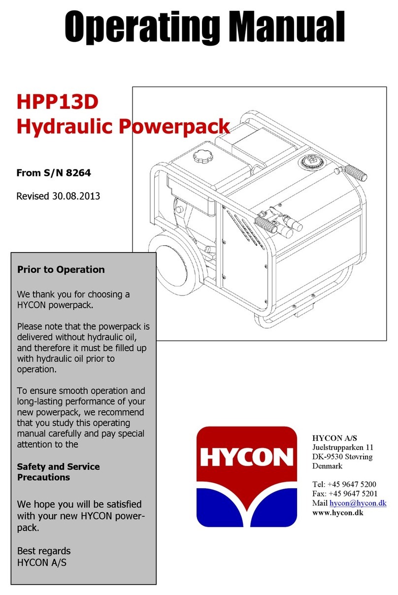
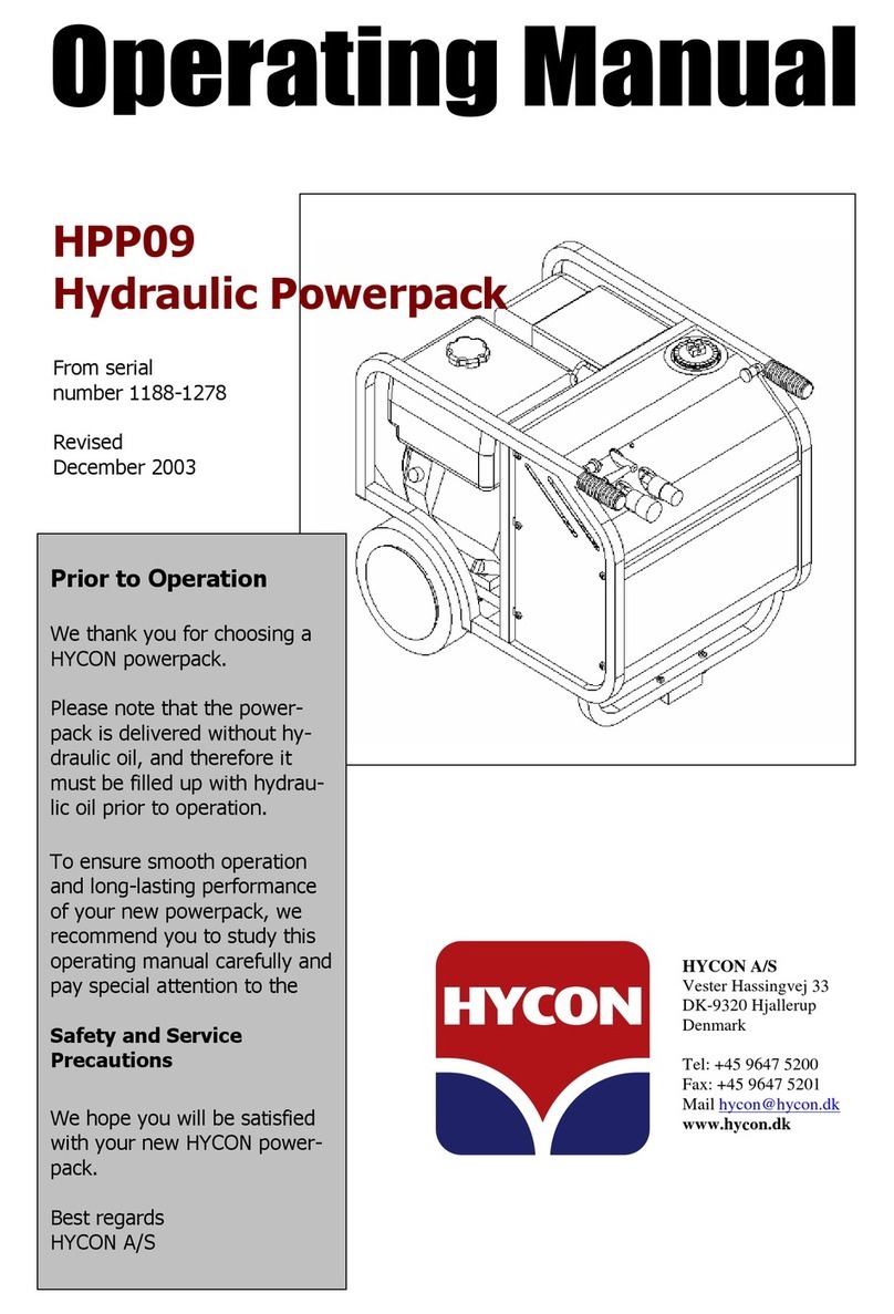
HYCON HPP26DMF User manual

HYCON A/S
Juelstrupparken 11
DK-9530 Støvring
Denmark
Tel: +45 9647 5200
Fax: +45 9647 5201
Mail hycon@hycon.dk
www.hycon.dk
HPP26DMF
Hydraulic Powerpack
From serial number: 11315
Revised
16.08.2016
Prior to Operation
We thank you for choosing a
HYCON powerpack.
Please note that the powerpack
is delivered without hydraulic
oil, and therefore it must be
filled up with hydraulic oil prior
to operation.
To ensure smooth operation
and long-lasting performance of
your new powerpack, we
recommend that you study this
operating manual carefully and
pay special attention to the
Safety and Service
Precautions
We hope you will be satisfied
with your new HYCON power-
pack.
Best regards
HYCON A/S

1
Contents
Page
Safety precautions ............................................................................................ 2
Filling up hydraulic oil ....................................................................................... 2
Technical data .................................................................................................. 3
Starting instructions ......................................................................................... 4
Setting of flow ................................................................................................ 4
Service, maintenance and hydraulic settings ...................................................... 5
Oil types .......................................................................................................... 6
Warranty conditions ......................................................................................... 6
Spare parts list ................................................................................................. 7

2
Safety Precautions
1. Always use protective earplugs. Daily long-lasting operation there is a risk of
hearing defects.
2. Always connect hoses before starting.
3. Never add fuel and oil when the engine is running.
4. In case of non-operation or performance of service, always turn off the engine.
5. Never start the engine without side covers.
6. Operation of the powerpack without tool connected and with lever at “ON” may
cause overheating of the system and damage to the powerpack.
7. When lifting the powerpack from a vehicle, we recommend the use of a crane.
8. The pressure relief valves are set at 160 bar from our plant. Never set them
higher.
9. Always use filters with by-pass. The use of filters without by-pass may blow the
hydraulic hoses and the filter cover.
Filling Up Hydraulic Oil
To fill up with hydraulic oil, loosen the
filter cover on top of the powerpack.
Remove the filter element (see photo),
and fill up with oil. When oil is showing
at the bottom of the filter unit, there is
enough oil on the powerpack.
Insert the filter element again, mount
the cover and the powerpack is ready
for use.
Please note: When connecting new extension
hoses, it is necessary to fill up with extra 2 litres of
oil. Therefore always top up the powerpack when
connecting new extension hoses.

3
Technical Data
Hydraulics
The HYCON HPP26DMF open centre Powerpack is designed in accordance with the
EHTMA categories D, E and F, which prescribe a performance of 30, 40 and 60 l.p.m.
respectively at 138 bar. The HYCON powerpack is fully compatible with and sufficient
for the common European tools.
The powerpack is mounted with a double pump (two independent hydraulic circuits),
and it has three connections for each circuit separately or both circuits simul-
taneously. This way the powerpack can operate two tools simultaneously. For a more
detailed description, please refer to the section about “Setting of Flow”
The powerpack is mounted with pressure relief valves to avoid a too high pressure.
Furthermore, the very efficient air cooling protects the powerpack against
overheating. The powerpack has no POR system, and the engine r.p.m. (oil flow) is
adjusted manually by means of the throttle.
Oil flow connection A 30 l.p.m. at 2000 r.p.m.
40 l.p.m. at 2600 r.p.m.
60 l.p.m. at 3600 r.p.m.
Oil flow connections B and C 15 l.p.m. at 2000 r.p.m.
20 l.p.m. at 2600 r.p.m.
30 l.p.m. at 3600 r.p.m.
Working pressure nominal 120 bar
Pressure relief valves Set at 160 bar
Pump Double gear pump
Oil temperature Max. 70° C
Capacity hydraulic oil tank Min. 11 litres/max. 15 litres
Capacity fuel tank 25 litres
Hydraulic system complete 16 litres
Filter system (filter element) 25 Micron with by-pass
Engine Lombardini 3-cylinder 26 HP (gross power)
4-stroke diesel
Fuel: Diesel
Engine oil 2.4 litres
Guaranteed sound power level LWA
Sound pressure level 1 m LPA
Dimensions (LxWxH) 1040x740x850 mm
Weight w/o hydraulic oil 230 kg

4
Starting Instructions
Please observe the starting instructions on the front of the powerpack.
Start: Check engine oil level
Check hydraulic oil level at sight glass
Connect hoses and tool
Switch fuel tap to “ON”
Turn ignition key
Wait until engine warning light disappears
Activate electric start
Set the flow – see below
Stop: Move all levers to “OFF“
Turn off the ignition switch
Turn the fuel tap to “OFF”
Setting of Flow
The powerpack has three connections, allowing for connection of two tools
simultaneously. The connections are marked A, B and C, respectively.
The oil flow can be adjusted by regulating the engine r.p.m. by means of the
throttle. Connection A can be set to 30-60 l.p.m. Connections B and C can be set to
15-30 l.p.m. Connection A cannot be used simultaneously with connections B and C.
Each connection is equipped with an ON-OFF lever. Connections not in use must be
set at OFF, and connections in use must be set at ON. Connections B and C can only
be used when connection A is OFF. Never turn the lever to ON if no tool is
connected.

5
Service, Maintenance and Hydraulic Settings
Service/Maintenance Daily Weekly Yearly
Hydraulic oil Check 1 x replacement
Hydraulic oil filter *) 1 x replacement
Check hoses (tighten up if needed)
Air filter 1 x replacement
Fuel filter 1 x replacement
*) use only filters with by-pass
Engine service
The engine must be serviced according to the Lombardini service book
Hydraulic Settings
Check the working pressure by means of test equipment. The test equipment must
comprise a pressure gauge, a flow meter and a valve for adjustment of pressure.
The pressure relief valves are placed on the valve block. There are two pressure
relief valves (one for each hydraulic circuit), and they must be adjusted individually.
The pressure relief valves are marked with B and C respectively.
1. Connect the test equipment to connection B, start the powerpack and move the B
lever to ON and the A and C levers to OFF. Then close the valve on the test
equipment and adjust the pressure relief valve B according to the technical data.
Adjust the pressure relief valve by loosening the lock nut and turning the
adjustment screw in or out. “In” increases the pressure, and “out” decreases the
pressure.
Retighten the lock nut after adjustment.
Connect the test equipment to connection C, start the powerpack and move lever
C to ON and levers A and B to OFF. Then close the valve on the test equipment
and adjust the pressure relief valve C according to the technical data.
2. Having adjusted the pressure relief valves correctly, set the working pressure to
100 bar by means of the valve on the test equipment. At 100 bar the oil flow
should correspond to the flow rate which the lever is set at (see Setting of Flow).
If correct pressure/oil flow cannot be achieved by following
the above instructions, the powerpack must be re-adjusted.
If the pressure/oil flow is then still incorrect, the pump is
defect and must be replaced.
6
Oil Types
The HYCON powerpack uses standard hydraulic oil, i.e. all types of mineral oil and
biodegradable oil, which comply with the following values:
Ambient temperature range Below 10°C
50°F
10 … 30°C
50 … 86°F
Above 30°C
86°F
Recommended oil viscosity grade VG 32 VG 46 VG 68
Recommended oil cleanliness
ISO 4406 /19/16 / NAS 1638 10
Permitted viscosity cSt
10 – 600
Viscosity index Minimum
100
Oil temperature area °C /°F -20 to 70 / -4 to 158

7
Warranty Conditions
We grant 12 months warranty from the first date of operation – however, not more
than 18 months from the date of delivery.
The warranty applies to faults that can be related to construction and production
errors.
Faults caused by incorrect operation, incorrect handling, lack of maintenance or the
like will not be accepted as warranty.
The warranty covers the parts necessary for repair and the suggested average time
needed for repair.
For further warranty details, please contact your local dealer.
HYCON A/S
Juelstrupparken 11
DK-9530 Støvring
Denmark
Martin Møller
Managing Director
26.07.2019
Table of contents
Other HYCON Power Pack manuals

HYCON
HYCON FLEX HPP14V User manual

HYCON
HYCON HPP18E FLEX User manual

HYCON
HYCON HPP09 Instruction manual

HYCON
HYCON HPP18E FLEX User manual

HYCON
HYCON HPP13D User manual

HYCON
HYCON HPP09 User manual

HYCON
HYCON HPP09 User manual

HYCON
HYCON HPP18V FLEX User manual

HYCON
HYCON HPP18E FLEX User manual

HYCON
HYCON HPP06 User manual