Hycontrol SW2 User manual

SMARTFOAM SENSORS
INSTALLATION AND OPERATION MANUAL
Hycontrol Ltd
Larchwood House, Orchard Street, Redditch, Worcestershire, B98 7DP, UK
Tel: 44 (0)1527 406800. Fax: 44 (0)1527 406810
email: sales@hycontrol.com website: www.hycontrol.com V1.5

Hycontrol Ltd V1.5
Page 2
CONTENTS
1 SPECIFICATION . 2
2 HOW IT WORKS 3
3 CONNECTIONS . 3
3.1 Indicators .. 4
4 INSTALLATION
4.1 Installing the Sensor in A Tank . 5
4.2 Cabling .. 7
5 COMMISSIONING
5.1 Setting-U 8
5.2 Sensitivity . 8
5.3 Res onse Time 9

Hycontrol Ltd V1.5
Page 3
1) SMARTFOAM SPECIFICATION
Power Supply: 24 V d.c. 100mA
Response Time: 1, 4, 10 seconds.
Sensitivity: 0 – [0 = dense foam, = light foam]
Nominal Impedance at each Sensitivity Setting (KΩ)
0 1 2 3 4 5 6 7 8
0.5 1.75 3.3 5 7.5 10 14 20 27 35
Fouling Immunity: Sensitivity to fouling <1% of sensitivity to foam with
Hycontrol Sensors.
Output: 'Volt-free' c/o contacts rated at 24 Volts d.c.
at 500 mA max
Connections: Screw terminals.
Cable: 4 /5 core cable. (e.g. type 16-2-4C, 16x0.2mm)
Head: Polypropylene, IP66
Dimensions: 20mm Diameter, Length 60, 100 or 150cm
Process entry: ¾” BSPT (R3/4) on standard version
Materials: Body – 316 Stainless steel, Insulators – PVDF
Design Pressure: 1.5 bars
Design Temperature: 80o C

Hycontrol Ltd V1.5
Page 4
J1 J2
SW2
SW1
1 2 3 4 5
Sens
Set
+ 24 - G
O/P
1
2
3
4
5
6
7
8
90
Sensitivity
Adjustment
0 - Low ( Dense foam)
5 - Normal
9 - High (light foam)
Response Time
Position for
normal response
Output termin ls
24Vdc, 500mA m x
ontact opens
if foam detected
Supply termin ls
Indic tors
Amber on = no foam
Green on = power
2) SMARTFOAM – HOW IT WORKS.
The SmartFoam is a new and unique roduct from Hycontrol designed to measure and
control foam in a single unit which is easy and quick to install. The sensor contains its own
transmitter located inside the head so it can connect directly to a rocess controller or a
um . The SmartFoam can be used to create an effective foam control system without the
need for any additional transmitter. It is designed to be robust for industrial use.
The sensor is designed using the IMA SensingTM technology which enables foam to be
measured reliably even when it is covered with a build-u of sticky material which frequently
ha ens during foam measurement. The sensor works by using a small current assing
through the foam into the liquid surface, which is used to measure the foam density.
3) CONNECTIONS
The terminals and adjustments are shown in Figure 1 below.
Figure 1 – CONNECT ONS and ADJUSTMENTS

Hycontrol Ltd V1.5
Page 5
3.1) Indicators
There are two indicators in the head to show the status. These can be seen in the
diagram above.
1. Green – Power on.
2. Amber – On when no foam is present. Off when foam is measured.
) INSTALLATION
.1) Installing the Sensor in a Tank
The sensor can be installed in a closed tank by connecting with the 3/4” BSP fitting. If the
sensor needs to be sealed into the tank, the fitting should be sealed by using PTFE ta e or a
sealing com ound. Alternatively the sensor can be fixed by a bracket over an o en tank.
Fit the sensor in a osition where the foam will come into contact with it. However it should
not be too close to metal structures (e.g. baffles or tank wall) as a “bridge” of foam can stick
between the sensor and the structure and cause false alarms. Ensure 50mm of clearance
exists between the end of the sensor and any other metal arts.
The sensor should be connected with a 4-core screened cable. The cable carries the ower
(24V dc) as well as the sensor out ut and in some cases the earth/return signal. See figure 1
for connections.
The sensor requires a return ath for the measurement to work correctly. If the foam is
measured in a metal tank, the return can be an earth/ground connection. If a lastic tank is
used then a se arate electrode in the water may be required or a connection to metal
i ework can be used.
The easiest return ath is sim ly the screwed fitting in connection with the metal tank which
rovides a return ath though the sensor. (See figure 2) Alternatively the return can be
connected via the cable screen and the earth nnetwork. (See figure 3)
Figure 2 – Metal tank
Direct return via
fitting
SmartFoam fitting
Connects to metal tank
To provide return path.

Hycontrol Ltd V1.5
Page 6
However, if a lastic tank is used, then an earth electrode is required in the liquid. An
electrode may be a sim le stainless steel rod or i e which is artially immersed in the
liquid. This should be connected using a wire to earth as shown in figure 4 with the sensor
cable screen also connected to earth/ground. Alternatively the earth electrode can be
connected directly to the sensor rocess fitting as shown in figure 5. If a metal i e is in
contact with the liquid this may be used in lace of an electrode.
It is essential that a return ath is connected for the measurement to work correctly.
Return via
ground Network
metal ground electrode
Plastic Tank
Figure 4 – Plastic tank
With return path using a ground
electrode and the network ground.
Figure 3 – Metal Tank
With return path via
ground network.

Hycontrol Ltd V1.5
Page 7
.2) Cabling and Connections
The easiest way to connect the sensor is to use a 4-core screened cable. The cable does
not need to be screened for shielding ur oses but the screen is a convenient way to
connect the earth return if the set-u in figure 3 or 4 is used. If the sensor is fitted to a metal
tank with the fitting connected to the tank as shown in figure 2 then the screen is not
required.
The sensor out ut has volt-free contacts which o en when foam is detected. This can be
used to switch 24V dc to a PLC or a um . Some PLC in uts can be wired directly to volt-
free contacts and can detect the contact closure. The out ut contacts are rovided by an
isolated solid state switch. The maximum load is 500mA. If switching inductive loads then a
su ressor or snubber should be fitted to rotect the out ut contacts.
The ower su ly required is 24V dc. The maximum current required is less than 100mA so
the cable rating is not critical. See figure 1 for connections.
Return via
probe fitting
metal ground
electrode
Plastic Tank
Figure 5 – Plastic Tank
With return path via
ground electrode and
fitting.

Hycontrol Ltd V1.5
Page 8
5) COMMISSIONING
5.1) Setting-Up
There is very little to set u as in most cases the sensor can be fitted without any
adjustment. However there are adjustments for sensitivity and res onse time, should they be
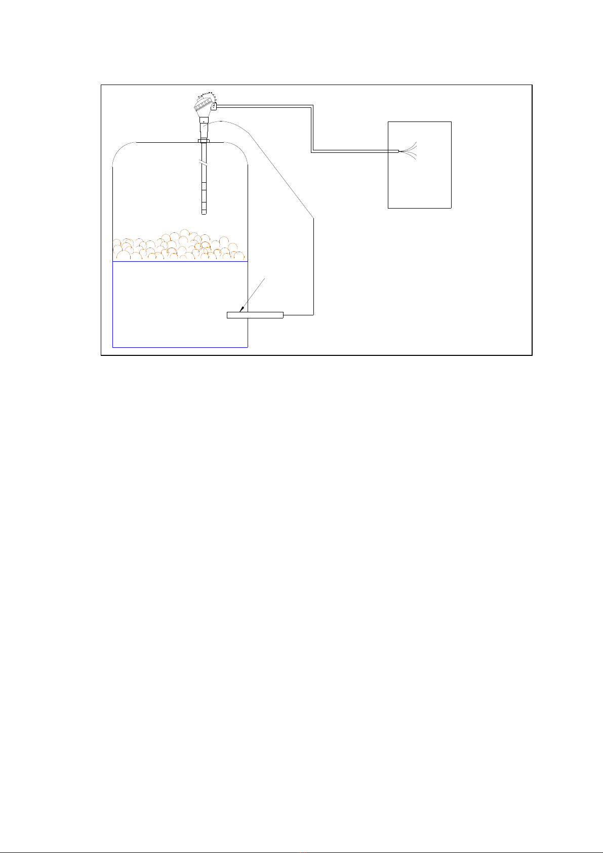
needed. To test the sensitivity arrange for the foam to increase to reach the sensor. The
sense electrode at the send of the sensor is the sensitive art. Once the foam makes a good
contact with the sense electrode the robe should be able to detect the foam. If it’s
im ractical to make foam for a test then a sim le test is to touch the end of the sensor
against the wall of the tank. This is a very coarse test and does not show that it will measure
the foam, however it will trigger the sensor to allow the connections to be tested.
If the test above does not trigger the sensor then there is almost certainly an earth return
roblem.
5.2) Sensitivity Setting
The sensitivity can be set by the small adjuster in the head. The adjustment is from 0 –9
where 0 is the lowest sensitivity. The factory setting of 5 is suitable for most a lications.
However if the foam is very light the sensitivity may need to be increased. Alternatively with
very dense sticky foam it is advisable to reduce the sensitivity. See Table 1 below for more
details of the sensitivity settings. .
If the sensor is in contact with foam but does not trigger then increase the sensitivity
setting to a higher figure.
Table 1 Sensitivity Adjustment – SW2
Sensitivity Setting Application
0 Liquid Lowest Sensitivity
1 Very dense heavy foam
2 Processed food with high salt level
3 Waste water with high solids
4 Waste water
5 Most applications Default Setting
6
7 Light foam from detergent
8
Very light foam Highest Sensitivity

Hycontrol Ltd V1.5
Page 9
5.3) Response Time
The res onse time is the time taken by the sensor to res ond to foam. The factory set
res onse time is 4 seconds. This is o timum for most a lications and allows sufficient time
for rejection of s lashing and s urious triggers. However in rare cases foam can build u
within a few seconds to a high level for which 4 seconds may be too slow. Ty ical fast
a lications are vacuum cooling and gas stri ing. To change the res onse time remove the
small white link on sw2 and refit as shown below. In cases of high s lashing the res onse
time can be increased to 10 seconds. See table 2 below.
Table 2 – Response Time adjustment
Application
Response
Setting SW1
Almost all
Standard – 4 seconds
Vacuum cooling
Fast – 1 second
Effluent Slow – 10 seconds
Table of contents
Popular Accessories manuals by other brands

Nexen
Nexen WEB CONTROL PH 16 user manual

IFM Electronic
IFM Electronic efector500 PI20 operating instructions

MICRO-EPSILON
MICRO-EPSILON eddyNCDT 3060 operating instructions

SWR
SWR ProGap S operating instructions

Rubbermaid
Rubbermaid Thermo-Electric Travel Cooler and Warmer Owner's manual & warranty information

Bosch
Bosch SCD 110 operating instructions