HYDAC FILTER SYSTEMS CSM-E User manual

CSM-E
ContaminationSensor Module -
Economy
Installation and Maintenance Instructions
English (translation of original instructions)
Keep for future reference.
Document No.: 3911629a

Imprint
Imprint
Manufacturer / publisher and responsible for the content:
HYDAC FILTER SYSTEMS GMBH
Industriestraße
66280 Sulzbach / Saar
Germany
Telephone:
+49 6897 509 01
Fax:
+49 6897 509 9046
E-mail:
filtersystems@hydac.com
Homepage:
www.hydac.com
Court of Registration:
Saarbrücken, HRB 17216
Executive director:
Mathias Dieter,
Dipl.Kfm. Wolfgang Haering
Documentation Representative
Mr. Günter Harge
c/o HYDAC International GmbH, Industriegebiet, 66280 Sulzbach / Saar
Telephone:
+49 6897 509 1511
Fax:
+49 6897 509 1394
E-mail:
guenter.harge@hydac.com
© HYDAC FILTER SYSTEMS GMBH
All rights reserved. No part of this work may be reproduced in any form (print,
photocopy or by other means) or processed, duplicated or distributed using
electronic systems without the written consent of the publisher.
These documents have been created and inspected with the greatest care.
However, errors cannot be ruled out completely.
All details are subject to technical modifications. Technical specifications are
subject to change without notice.
CSM-E en(us) Page 2 / 64
MoWa CSM-E 3911629a en-us 2017-12-11.docx 2017-12-11

Content
Content
Imprint............................................................................................................2
Documentation Representative ...................................................................2
Content ..........................................................................................................3
Preface...........................................................................................................5
Technical Support........................................................................................5
Modifications to the Product ........................................................................5
Warranty......................................................................................................5
Using the documentation.............................................................................6
Safety information ........................................................................................7
Signal words and their meaning in the safety information and
instructions ..................................................................................................7
Structure of the safety information and instructions.....................................8
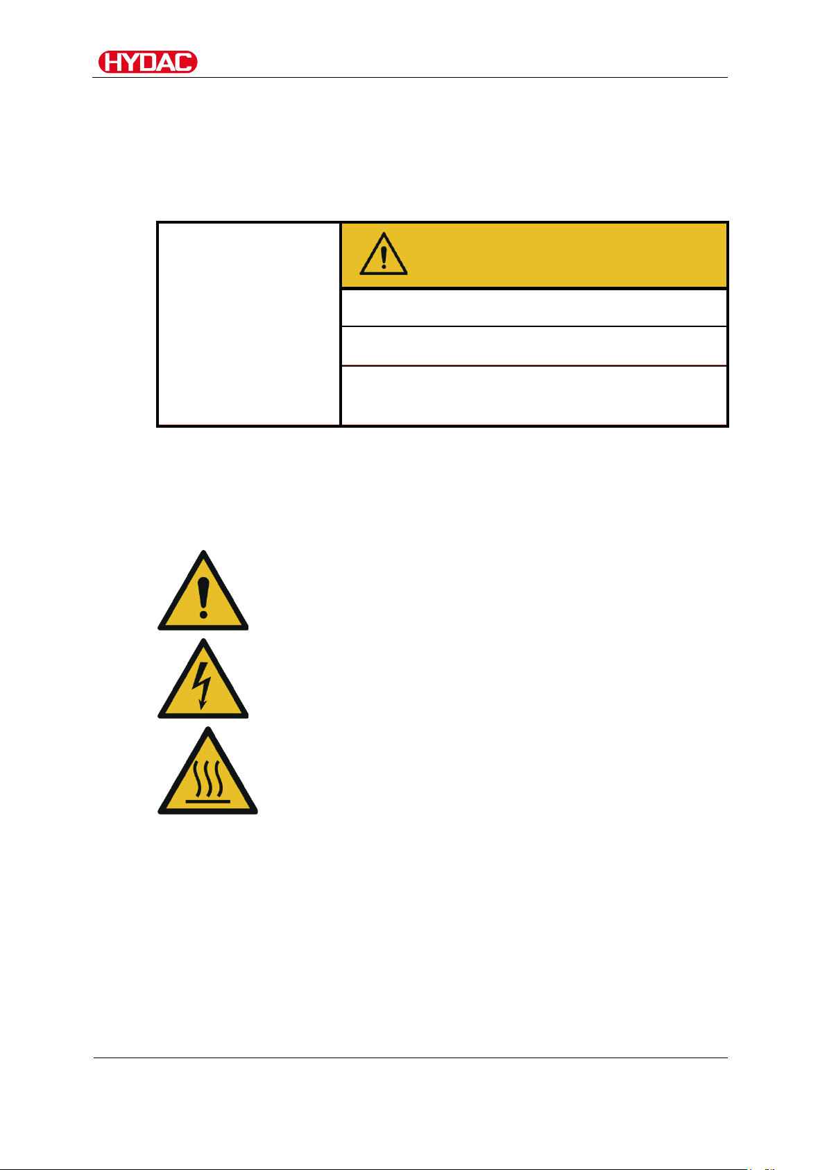
Warning signs used .....................................................................................8
Signs used for giving orders ........................................................................9
Others used symbols...................................................................................9
Signs used for the required specialist personnel .......................................10
Specialist personnel – Mechanical .........................................................10
Specialist personnel – Electricity ............................................................10
Observe regulatory information .................................................................10
Proper/Designated Use .............................................................................11
Improper Use or Use Deviating from Intended Use ...................................11
Qualifications of personnel / target group ..................................................13
Wear suitable clothing ...............................................................................15
Procedure in an Emergency ......................................................................15
Firefighting/Extinguishing Fires ..............................................................15
Unpacking the unit......................................................................................16
Transporting the unit..................................................................................16
Storing the unit ...........................................................................................16
Decoding the name plate ...........................................................................17
Checking the scope of delivery .................................................................18
Characteristics of the unit..........................................................................19
Unit components.........................................................................................20
Hydraulic circuit powerpack ......................................................................21
Drilling template for fastening ....................................................................22
Making the hydraulic connections to the unit..........................................23
Installing ContaminationSensor .................................................................23
Installing additional sensor(s) AS1000 / AS3000 / HLB1400.....................25
CSM-E en(us) Page 3 / 64
MoWa CSM-E 3911629a en-us 2017-12-11.docx 2017-12-11

Content
Overview of the hydraulic connections ......................................................26
Notes on pipes/hosing ...............................................................................27
Connecting the IN suction port ...............................................................28
Hooking up tank connection OUT...........................................................29
Connecting drain port LEAK (with CSM-E 1xxx-2 only…) ......................29
For the version with the magnetic coupling (CSM-E 1xxx-4…)
please note the following:.......................................................................30
Electrical connection of the unit................................................................31
Electrical connection of the ContaminationSensor CS1000 ......................32
Electrical connection of the AquaSensor AS1000 / AS3000
(optional)....................................................................................................32
Electrical connection of the HYDACLab HLB1400 (optional).....................32
Electrical connection of the CSI-C-11 (optional) ........................................32
Starting up the unit .....................................................................................33
Adjusting the counter balance valve.........................................................33
Required tools ...........................................................................................34
Setting the counter balance valve with a pressure gauge..........................35
Setting up the counter balance valve without pressure gauge...................38
Mounting accessories ................................................................................40
Performing maintenance............................................................................41
Clean the suction strainer..........................................................................42
Errors and troubleshooting........................................................................44
Taking the unit out of operation ................................................................44
Shutting down the unit ...............................................................................45
Disposing of the unit ..................................................................................45
Ordering spare parts ..................................................................................46
Ordering accessories .................................................................................49
Technical Data.............................................................................................53
Appendix .....................................................................................................56
Customer service.......................................................................................56
Unit dimensions .........................................................................................57
Dimensions with CS1000, AS1000 and CSI-C11 ...................................57
Dimensions with CS1000, HLB1400 and CSI-C11.................................58
Model code ................................................................................................59
Explanation of terms and abbreviations.....................................................60
Index..........................................................................................................61
CSM-E en(us) Page 4 / 64
MoWa CSM-E 3911629a en-us 2017-12-11.docx 2017-12-11

Preface
Preface
This operating manual was made to the best of our knowledge. Nevertheless
and despite the greatest care, it cannot be excluded that mistakes could have
crept in. Therefore please understand that in the absence of any provisions
to the contrary hereinafter our warranty and liability – for any legal reasons
whatsoever – are excluded in respect of the information in this operating
manual. In particular, we shall not be liable for lost profit or other financial
loss. This exclusion of liability does not apply in cases of intent and gross
negligence. Moreover, it does not apply to defects which have been
deceitfully concealed or whose absence has been guaranteed, nor in cases
of culpable harm to life, physical injury and damage to health. If we
negligently breach any material contractual obligation, our liability shall be
limited to foreseeable damage. Claims due to Product Liability shall remain
unaffected.
Technical Support
If you have any questions, suggestions, or encounter any problems of a
technical nature, please don't hesitate to contact us. When contacting us,
please always include the model/type designation and article no. of the
product:
Fax:
+49 6897 509 9046
E-mail:
filtersystems@hydac.com
Modifications to the Product
We would like to point out that changes to the product (e.g. purchasing
options, etc.) may result in the information in the operating instructions no
longer being completely accurate or sufficient.
After modification or repair work that affects the safety of the product has
been carried out on components, the product may not be returned to
operation until it has been checked and released by a HYDAC technician.
Please notify us immediately of any modifications made to the product
whether by you or a third party.
Warranty
For the warranty provided by us, please refer to the terms of delivery of
HYDAC FILTER SYSTEMS GMBH.
You will find these under www.hydac.com -> Legal information.
CSM-E en(us) Page 5 / 64
MoWa CSM-E 3911629a en-us 2017-12-11.docx 2017-12-11

Preface
Using the documentation
Note that the method described for locating specific information
does not release you from your responsibility of carefully reading
these instructions prior to starting the unit up for the first time and
at regular intervals in the future.
What do you want to know?
I determine which topic I am looking for.
Where can I find the information I’m looking for?
The document has a table of contents at the beginning. I select the chapter
I'm looking for and the corresponding page number.
de
HYDACFiltertechnikGmbH
BeWa123456ade
Se ite x
Produkt/Kapitel
200x-xx- xx
The documentation number with its index enables you to order another copy
of the operating and maintenance instructions. The index is incremented by
one digit every time the manual is revised or changed.
Chapter description
Page number
Edition date
Document language
Documentation no.
with index/
file name
CSM-E en(us) Page 6 / 64
MoWa CSM-E 3911629a en-us 2017-12-11.docx 2017-12-11

Safety information
Safety information
The unit was built according to the statutory provisions valid at the time of
delivery and satisfies current safety requirements.
Any residual hazards are indicated by safety precautions and are described
in the Installation and Maintenance Instructions.
Observe all safety and warning instructions attached to the unit. They must
always be complete and legible.
Do not operate the unit unless all the safety devices are present.
Secure the hazardous areas which may arise between the unit and other
equipment.
Maintain the unit inspection intervals prescribed by law.
Document the results in an inspection certificate and keep it until the next
inspection.
Signal words and their meaning in the safety information and
instructions
In these instructions you will find the following signal words:
DANGER
DANGER – The signal word indicates a hazardous situation with a high level
of risk, which, if not avoided, will result lethal or serious injury.
WARNING
WARNING – The signal word indicates a hazardous situation with a medium
level of risk, which, if not avoided, can result lethal or serious injury.
CAUTION
CAUTION – The signal word indicates a hazardous situation with a low level
of risk, which, if not avoided, can result in minor or moderate injury.
NOTICE
NOTICE – The signal word indicates a hazardous situation with a high level
of risk, which, if not avoided, will result in damage to property.
CSM-E en(us) Page 7 / 64
MoWa CSM-E 3911629a en-us 2017-12-11.docx 2017-12-11

Safety information
Structure of the safety information and instructions
All warning instructions in this manual are highlighted with pictograms and
signal words. The pictogram and the signal word indicate the severity of the
danger.
Warning instructions listed before an activity are laid out as follows:
HAZARD SYMBOL
SIGNAL WORD
Type and source of danger
Consequence of the danger
►Measures to avert danger
Warning signs used
These signs are listed for all safety information and instructions in these
operating instructions which indicate particular hazards to persons, property
or the environment.
Hazard, general
Danger due to electrical voltage / current
Risk of burns due to hot surfaces
CSM-E en(us) Page 8 / 64
MoWa CSM-E 3911629a en-us 2017-12-11.docx 2017-12-11

Safety information
Signs used for giving orders
These symbols are listed for all safety information and instructions in these
operating instructions which indicate particular hazards to persons, property
or the environment.
Read and observe the operation and maintenance
instructions.
Others used symbols
The following symbols found you in this operation instructions.
Tip for handling the product
Tools required
CSM-E en(us) Page 9 / 64
MoWa CSM-E 3911629a en-us 2017-12-11.docx 2017-12-11

Safety information
Signs used for the required specialist personnel
These symbols show the required training/knowledge for installation work
and/or maintenance work.
Specialist personnel – Mechanical
Only specialist personnel with training as mechanics and
the following knowledge:
•Safe handling/use of tools
•Fitting and connection of hydraulic tubes and
connections
•Product-specific knowledge
•Knowledge about how to handle operating media.
Specialist personnel – Electricity
Only specialist personnel with training as electricians and
the following knowledge:
•Safe handling/use of tools
•Fitting and connection of electrical lines, electrical
machinery, sockets, etc.
•Checking the phase sequence
•Product-specific knowledge
•Knowledge about how to handle operating media.
Observe regulatory information
Observe the following regulatory information and guidelines:
•Legal and local regulations for accident prevention
•Legal and local regulations for environmental protection
•Country-specific regulations, organization-specific regulations
CSM-E en(us) Page 10 / 64
MoWa CSM-E 3911629a en-us 2017-12-11.docx 2017-12-11

Safety information
Proper/Designated Use
Use the unit only for the application described in the following.
The ContaminationSensor Module CSM-E was developed for the continuous
monitoring for solid particle contamination in hydraulic systems.
Proper/designated use of the product extends to the following:
•Observing all instructions contained in the instruction manual.
•Performing inspection and maintenance work.
Improper Use or Use Deviating from Intended Use
DANGER
Danger due to unanticipated use of the unit
Bodily injury and damage to property will result
when operated improperly.
►
Never operate the unit in potentially explosive
atmospheres.
►The unit is only to be used with permissible
media.
Any use extending beyond this or deviating therefrom shall not be considered
intended use. HYDAC Filter Systems GmbH will assume no liability for any
damage resulting from such use. The user alone shall assume any and all
associated risk.
Improper use or use deviating from intended may result in hazards and/or will
damage the unit. Examples of improper use:
oOperation in potentially explosive atmospheres
oOperation with a non-approved medium.
oOperation under non-approved conditions
oOperation when the system equipment or safety devices are defective
omodifications to the unit made by the user or purchaser
oImproper monitoring of unit components that are subject to wear and
tear
oimproperly performed repair work
CSM-E en(us) Page 11 / 64
MoWa CSM-E 3911629a en-us 2017-12-11.docx 2017-12-11

Safety information
NOTICE
Impermissible operating media
The unit will be destroyed
►The unit is only to be used with mineral oils or mineral oil-based
raffinates.
NOTICE
Highly contaminated fluid
The pump will become worn out / damaged
►For long-term operation, pump only fluid with a maximum
contamination of ISO 22/20/18
CSM-E en(us) Page 12 / 64
MoWa CSM-E 3911629a en-us 2017-12-11.docx 2017-12-11

Safety information
Qualifications of personnel / target group
Staff who work with the powerpack must be aware of the dangers involved,
must be over the age of 14 and must be without any physical impediments in
regard to the industrial environment.
These operating instructions is intended for:
Auxiliary personnel:
Such persons have been instructed about the product and informed about
potential hazards that can result from improper use.
Operating personnel:
Such persons have been instructed in power unit operation and are aware of
potential hazards due to improper use.
Specialist personnel:
Such persons with corresponding specialist training and several years' work
experience. They are able to assess and perform the work assigned to them,
they are also able to recognize potential hazards.
CSM-E en(us) Page 13 / 64
MoWa CSM-E 3911629a en-us 2017-12-11.docx 2017-12-11

Safety information
Activity
Person
Knowledge
Transport / storage
Forwarding
agent
Specialist
personnel
•Proof of knowledge of cargo
securing instructions
•Safe handling/operation of
hoisting and lifting equipment
Hydraulic / electrical
installation,
First commissioning,
maintenance,
Troubleshooting,
Repair,
Decommissioning,
Disassembly
Specialist
personnel
•Safe handling/use of tools
•Fitting and connection of
hydraulic tubes and
connections
•Fitting and connection of
electrical lines, electrical
machinery, sockets, etc.
•Checking the phase sequence
•Product-specific knowledge
Operation
Operations control
Specialist
personnel
•Product-specific knowledge
•Knowledge about how to
handle operating media.
•Knowledge about
contamination due to solids
and water
Disposal
Specialist
personnel
•Proper and environmentally-
friendly disposal of materials
and substances
•Decontamination of
contaminants
•Knowledge about reuse
CSM-E en(us) Page 14 / 64
MoWa CSM-E 3911629a en-us 2017-12-11.docx 2017-12-11

Safety information
Wear suitable clothing
Loose-fitting clothing increases the risk of being caught or being drawn in on
rotating parts, and the risk of getting caught on protruding parts. You can be
severely injured or killed.
•Wear close-fitting clothing.
•Do not wear any rings, chains or any other jewelry.
•Wear work safety shoes.
Procedure in an Emergency
In case of emergency, switch off the power unit or disconnect it.
Firefighting/Extinguishing Fires
Use a powder extinguisher that corresponds to fire class B as per EN EN 2 to
extinguish any fires.
Maintain a minimum safe distance from electrical components. For a mains
voltage of up to 1000 V, the minimum safe distance is 1 m.
CSM-E en(us) Page 15 / 64
MoWa CSM-E 3911629a en-us 2017-12-11.docx 2017-12-11

Unpacking the unit
Unpacking the unit
The unit is function- and leak-tested in the factory and properly packed. The
connectors are closed off so that no contamination can enter the unit while it
is in transit.
When receiving and unpacking the unit, check it for damage in transit.
Dispose of the packaging material in an environmentally friendly manner.
Transporting the unit
Only transport the unit as follows:
-
Carry the unit by hand holding the pump and fan cover.
-
Transport the unit on the rubber buffers in an upright position.
Storing the unit
Rinse and drain the unit completely before putting it into extended storage.
Store the unit in a clean, dry place. Store the unit on the rubber buffers in an
upright position.
CSM-E en(us) Page 16 / 64
MoWa CSM-E 3911629a en-us 2017-12-11.docx 2017-12-11

Decoding the name plate
Details for identifying the power unit can be found on the type labels on the
unit and the components.
Item
->
Description
(1)
->
Name plate for power unit
(2)
->
Name plate of electric motor
(3)
->
Model code; for details, see page 59
Max. INLET press
->
Maximum pressure at the inlet section
Max. Flow rate
->
Maximum flow rate
Weight
->
Weight when empty
CSM-E en(us) Page 17 / 64
MoWa CSM-E 3911629a en-us 2017-12-11.docx 2017-12-11

Checking the scope of delivery
Upon receiving the CSM check it for any damage in transit. Do not put the
CSM into operation unless it is in perfect condition. Report any damages in
transit to the transport company or the responsible agent immediately. Do not
put the unit into operation.
The following items are supplied:
Item
Qty
Designation
- 1 ContaminationSensor Module, CSM-E
- 4 Fastening screws for the ContaminationSensor
- 1 Installation and Maintenance Instructions, this document
CSM-E en(us) Page 18 / 64
MoWa CSM-E 3911629a en-us 2017-12-11.docx 2017-12-11

Characteristics of the unit
The gear pump sucks the oil to be analyzed and funnels it to the
ContaminationSensor where the solid particles are detected by an optical
sensor, divided up into classes by size and counted.
Any air bubbles contained in the oil may skew the measurement results as
they, like particulate contamination, cause the measurement cell to generate
signals. For this reason, the powerpack is fitted with an air release line. Its
job is to suppress any existing air bubbles, within the realm of what is
technically possible, to such an extent that the measurement result is not
skewed or is only negligibly skewed.
The highest pressure possible in the ContaminationSensor is targeted as oil
with increasing pressure can release an increasing quantity of air (reference
value: approx. 8% air per bar). This is achieved using a valve situated
downstream of the CS.
However, pressurized air cannot be immediately dissolved in oil,
consequently a path is provided for between the pump and the sensor.
CSM-E en(us) Page 19 / 64
MoWa CSM-E 3911629a en-us 2017-12-11.docx 2017-12-11

Unit components
Unit components
Item Designation
1 Electric motor
2 Gear pump (with or without leakage oil connection depending on
order)
3 Pressure relief valve
4 Counter balance valve
5 Suction strainer, 400 µm
6
Suction port (IN)
7 Tank connection (OUT)
8 Leakage oil connection (LEAK) (optional)
9 Fastening screws for the ContaminationSensor CS1000
21 Rubber buffer for assembly onto connection block
22
Rubber buffer for assembly onto electric motor
23 Screw plug /
Cavity for the AquaSensor AS1000 / AS3000
24 Flange port for the ContaminationSensor CS1000
CSM-E en(us) Page 20 / 64
MoWa CSM-E 3911629a en-us 2017-12-11.docx 2017-12-11
Table of contents
Other HYDAC FILTER SYSTEMS Measuring Instrument manuals
Popular Measuring Instrument manuals by other brands

PCB Piezotronics
PCB Piezotronics 354B20 Installation and operating manual

RMG
RMG TERZ 94 operating instructions

Beckman Coulter
Beckman Coulter EPICS XL manual

EMH metering
EMH metering NXT4 Instructions for use

Macnaught
Macnaught BOP IM012EB-01 instruction manual

Niigata seiki
Niigata seiki GDCS-150D instruction manual