HYDACELECTRONIC HDA 4800 User manual

Benutzerhandbuch
(Originalanleitung)
User manual
(Translation of original
instructions)
Notice d’utilisation
(Traduction de l’original)
Druckmessumformer
Pressure transducer
Transmetteurs de
Pression
HDA 4800
Mat –Nr. 669868 / Stand: 21.06.2013 D/E/F

2 HDA 4800
Stand: 21.06.2013 HYDAC ELECTRONIC GMBH Mat. Nr.: 669868
D
Impressum
Herausgeber und verantwortlich für den Inhalt:
HYDAC ELECTRONIC GMBH
Hauptstraße 27
D - 66 128 Saarbrücken
Telefon: +49 6897 509 1719
Fax: +49 6897 509 1726
Web: http://www.hydac.com
Geschäftsführer: Mathias Dieter, Dr. Franz Josef Eckle
Registergericht: Saarbrücken
Handelsregister HRB 8707
Dokumentationsbevollmächtigter
Herr Günter Harge
c/o HYDAC INTERNATIONAL GMBH, Industriegebiet, 66280
Sulzbach / Saar
Telefon: +49 6897 509 1511
Fax: +49 6897 509 1394
© HYDAC ELECTRONIC GMBH
Dieses Handbuch, einschließlich der darin enthaltenen
Abbildungen, ist urheberrechtlich geschützt. Drittanwendungen
dieses Handbuchs, welche von den urheberrechtlichen
Bestimmungen abweichen, sind verboten. Die Reproduktion,
Übersetzung sowie die elektronische und fotografische
Archivierung und Veränderung bedarf der schriftlichen
Genehmigung durch den Hersteller. Zuwiderhandlungen
verpflichten zu Schadenersatz.
Änderungsvorbehalt
Jegliche Änderungen, die dem technischen Fortschritt dienen,
vorbehalten.

HDA 4800 3
Stand: 21.06.2013 HYDAC ELECTRONIC GMBH Mat. Nr.: 669868
D
Inhalt
1Allgemeines _______________________________________________________5
2Sicherheitshinweis__________________________________________________5
3Montage __________________________________________________________5
4Anschlussbelegung_________________________________________________6
5Technische Daten___________________________________________________7
6Bestellangaben_____________________________________________________8
7Zubehör___________________________________________________________9
7.1 Elektrisch................................................................................................................9
7.2 Mechanisch..........................................................................................................11
8Geräteabmessungen _______________________________________________12

4 HDA 4800
Stand: 21.06.2013 HYDAC ELECTRONIC GMBH Mat. Nr.: 669868
D
Vorwort
Für Sie, den Benutzer unseres Produktes, haben wir in dieser
Dokumentation die wichtigsten Hinweise zum Bedienen und
Warten zusammengestellt.
Sie dient Ihnen dazu, das Produkt kennen zu lernen und seine
bestimmungsgemäßen Einsatzmöglichkeiten optimal zu nutzen.
Diese Dokumentation muss ständig am Einsatzort verfügbar
sein.
Bitte beachten Sie, dass die in dieser Dokumentation
gemachten Angaben der Gerätetechnik zu dem Zeitpunkt der
Literaturerstellung entsprechen. Abweichungen bei technischen
Angaben, Abbildungen und Maßen sind deshalb möglich.
Entdecken Sie beim Lesen dieser Dokumentation Fehler oder
haben weitere Anregungen und Hinweise, so wenden Sie sich
bitte an:
HYDAC ELECTRONIC GMBH
Technische Dokumentation
Hauptstraße 27
66128 Saarbrücken
-Deutschland-
Tel: +49(0)6897 / 509-01
Fax: +49(0)6897 / 509-1726
Die Redaktion freut sich über Ihre Mitarbeit.
„Aus der Praxis für die Praxis“

HDA 4800 5
Stand: 21.06.2013 HYDAC ELECTRONIC GMBH Mat. Nr.: 669868
D
1 Allgemeines
Falls Sie Fragen bezüglich der technischen Daten oder Eignung für Ihre Anwendungen
haben, wenden Sie sich bitte an unseren technischen Vertrieb.
Die Druckmessumformer HDA 4800 werden einzeln auf einem rechnergesteuerten Prüfplatz
abgeglichen und einem Endtest unterzogen. Sie sind wartungsfrei und sollten beim Einsatz
innerhalb der Spezifikationen (siehe Technische Daten) einwandfrei arbeiten. Falls trotzdem
Fehler auftreten, wenden Sie sich bitte an den HYDAC-Service. Fremdeingriffe in das Gerät
führen zum Erlöschen jeglicher Gewährleistungsansprüche.
2 Sicherheitshinweis
Überprüfen Sie vor der Inbetriebnahme den Zustand des Gerätes sowie des mitgelieferten
Zubehörs. Lesen Sie vor der Inbetriebnahme des Gerätes die Bedienanleitung und stellen
Sie sicher, dass das Gerät für Ihre Anwendung geeignet ist.
Falsche Handhabung bzw. die Nichteinhaltung von Gebrauchshinweisen oder technischen
Angaben kann zu Sach- und / oder Personenschäden führen.
3 Montage
Die Druckmessumformer können über den Gewindeanschluss direkt an der Hydraulikanlage
montiert werden. Um in kritischen Anwendungsfällen (z.B. starke Vibrationen oder Schläge)
einer mechanischen Zerstörung vorzubeugen, empfehlen wir den Druckmessumformer
mittels einer Schelle mit Elastomereinsatz zu befestigen, sowie den Hydraulikanschluss über
eine Minimessleitung zu entkoppeln. Die empfohlene Einbaulage für hydraulische
Anwendungen ist senkrecht mit dem Druckanschluss nach oben, für pneumatische
Anwendungen senkrecht mit dem Druckanschluss nach unten. Das Anzugsdrehmoment für
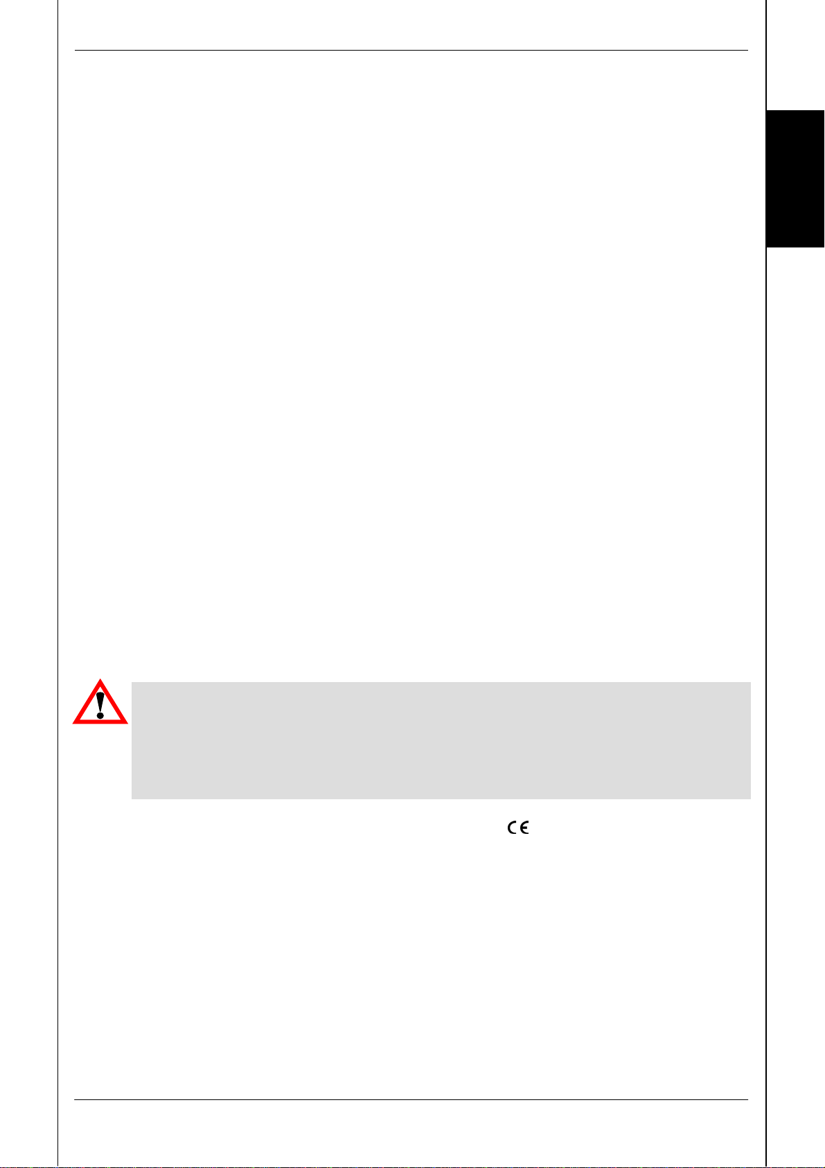
den G 1/4 A Gewindeanschluss beträgt ca. 20 Nm. Der elektrische Anschluss sollte von
einem Fachmann nach den jeweiligen Landesvorschriften durchgeführt werden (VDE 0100 in
Deutschland).
ACHTUNG:
Das Einschrauben des HDA 4800 muss mit einem passenden Maulschlüssel
(Schlüsselweite 27) am Sechskant des Druckanschlusses erfolgen.
Eine unsachgemäße Montage, wie z. B. durch manuelles Eindrehen über das
Gehäuse, kann zu Beschädigungen am Gehäuse, bis hin zum vollständigen
Ausfall des Gerätes führen.
Die Druckmessumformer der Serie HDA 4800 tragen das - Zeichen. Eine
Konformitätserklärung ist auf Anfrage erhältlich. Es gelten die EMV-Normen: EN 61000-6-1,
EN 61000-6-2, EN 61000-6-3 und EN 61000-6-4. Die Forderungen der Normen werden nur
bei ordnungsgemäßer und fachmännischer Erdung des Druckmessumformergehäuses
erreicht. Beim Einschrauben in einen Hydraulikblock ist es ausreichend, wenn der Block
über das Hydrauliksystem geerdet ist. Bei einer Schlauchmontage muss das Gehäuse
separat geerdet werden.

6 HDA 4800
Stand: 21.06.2013 HYDAC ELECTRONIC GMBH Mat. Nr.: 669868
D
Zusätzliche Montagehinweise, die erfahrungsgemäß den Einfluss elektromagnetischer
Störungen reduzieren:
•Möglichst kurze Leitungsverbindungen herstellen.
•Leitungen mit Schirm verwenden (z.B. LIYCY 4 x 0,5 mm²)
•Der Kabelschirm ist in Abhängigkeit der Umgebungsbedingungen fachmännisch und zum
Zweck der Störunterdrückung einzusetzen.
•Direkte Nähe zu Verbindungsleitungen von Leistungsverbrauchern oder störenden Elektro-
oder Elektronikgeräten ist möglichst zu vermeiden.
4 Anschlussbelegung
Stecker Binder Serie 714 M18
Pin HDA
4844 - A
HDA
4844– B
HDA
4844 - E
1 n.c. +UB+UB
2 Signal + Signal Signal
3 Signal - 0 V 0 V
4 n.c. n.c. n.c.
EN175301 – 803 (DIN 43650)
Pin HDA
4845 - A
HDA
4845– B
HDA
4845 - E
1 Signal + +UB+UB
2 Signal - 0 V 0 V
3 n.c. Signal Signal
4 Gehäuse Gehäuse Gehäuse
M12x1
Pin HDA
4846 - A
HDA
4846– B
HDA
4846 - E
1 Signal + +UB+UB
2 n.c. n.c n.c
3 Signal - 0 V 0 V
4 n.c. Signal Signal
2 3
1 4
1
3
2

HDA 4800 7
Stand: 21.06.2013 HYDAC ELECTRONIC GMBH Mat. Nr.: 669868
D
5 Technische Daten
Eingangskenngrößen
Messbereiche (bar) 6; 16; 60; 100; 250; 400; 600
Überlastbereich (bar) 15; 32; 120; 200; 500; 800; 1000
Berstdruck (bar) 100; 200; 300; 500; 1000; 2000; 2000
Mechanischer Anschluss G1/4A DIN 3852
Anzugsdrehmoment 20 Nm
Medienberührende Teile Anschlussstück: Edelstahl
Dichtung: FPM
Ausgangsgrößen
Signalausgang, zulässige Bürde 4 .. 20 mA, 2-Leiter
R
Lmax = (UB– 10 V) / 20 mA [kΩ]
0 ..10 V, 3-Leiter
R
Lmin = 2 kΩ
0 .. 20 mA, 3-Leiter (Quelle)
R
Lmax = (UB– 7 V) / 20 mA [kΩ]
Genauigkeit nach DIN 16086,
Grenzpunkteinstellung
≤± 0,125 % FS typ.
≤± 0,25 % FS max.
Genauigkeit bei Kleinstwerteinstellung
(B.F.S.L.)
≤± 0,06 % FS typ.
≤± 0,125 % FS max.
Temperaturkompensation
Nullpunkt
≤± 0,005 % FS / °C typ.
≤± 0,01 % FS / °C max.
Temperaturkompensation
Spanne
≤± 0,005 % FS / °C typ.
≤± 0,01 % FS / °C max.
Nicht-Linearität bei Grenzpunkteinstellung
nach DIN 16086
≤± 0,15 % FS max.
Hysterese ≤± 0,1 % FS max.
Wiederholbarkeit ≤± 0,05 % FS
Anstiegszeit ≤1 ms
Langzeitdrift ≤± 0,1 % FS typ. / Jahr
Umgebungsbedingungen
Kompensierter Temperaturbereich -25 .. +85 °C
Betriebstemperaturbereich1) -40 .. +85 °C / -25 .. +85 °C
Lagertemperaturbereich -40 .. +100 °C
Mediumstemperaturbereich1) -40 .. +100 °C / -25 .. +100 °C
- Zeichen EN 61000-6-1 / 2 / 3 /4
-Zeichen2) Zertifikat-Nr.: E318391
Vibrationsbeständigkeit nach
DIN EN 60068-2-6 bei 10 ..500 Hz
≤20 g
Schutzart nach IEC 60529 IP 65 (Stecker EN175301 – 803 (DIN 43650)
und Binder 714 M18)
IP 67 (M12x1 Stecker, bei Verwendung einer
IP 67 Kupplungsdose)
Sonstige Größen
Versorgungsspannung
Bei Einsatz gemäß UL-Spezifikation
10 .. 30 V DC 2-Leiter
12 .. 30 V DC 3-Leiter
-limited energy- gemäß
9.3 UL 61010,Class2; UL 1310/1585;LPS UL 60950
Restwelligkeit Versorgungsspannung ≤5 %
Stromaufnahme (Signalausgang Spannung) ≤15 mA
Lebensdauer > 10 Mio. Lastwechsel, 0 .. 100 % FS
Gewicht ca. 180 g
Anmerkung:
Verpolungsschutz der Versorgungsspannung, Überspannungs-, Übersteuerungsschutz,
Lastkurzschlussfestigkeit sind vorhanden.
FS (Full Scale) = bezogen auf den vollen Messbereich, B.F.S.L.= Best Fit Straight Line
1) -25°C mit FPM-Dichtung, -40°C auf Anfrage.
2) Umgebungsbedingungen gemäß 1.4.2 UL 61010-1; C22.2 No. 61010-1

8 HDA 4800
Stand: 21.06.2013 HYDAC ELECTRONIC GMBH Mat. Nr.: 669868
D
6 Bestellangaben
H D A 4 8 4 X - X – XXX - 000
Ausführung (Technologie)
8 = DMS auf Edelstahlmembrane ± 0,25 % max.
Anschlussart, mechanisch
4 = G1/4 A DIN 3852 (außen)
Anschlussart, elektrisch
4 = Gerätestecker 4-pol. Binder Serie 714 M18,
(ohne Kupplungsdose)
5 = Gerätestecker 3-pol. + PE, EN175301-803 (DIN 43650)
(inklusive Kupplungsdose)
6 = Gerätestecker M12x1, 4-pol.
(ohne Kupplungsdose)
Signal
A = 4 .. 20 mA, 2-Leiter
B = 0 .. 10 V, 3-Leiter
E = 0 .. 20 mA, 3-Leiter (Quelle)
Druckbereich in bar
006; 016; 060; 100; 250; 400; 600
Modifikationsnummer
000 = Standard
Anmerkung:
Bei Geräten mit anderer Modifikationsnummer ist das Typenschild bzw. die mitgelieferte technische
Änderungsbeschreibung zu beachten.

HDA 4800 9
Stand: 21.06.2013 HYDAC ELECTRONIC GMBH Mat. Nr.: 669868
D
7 Zubehör
7.1 Elektrisch
Mit elektrischer Anschlussart „4“: (Gerätestecker Binder Serie 714 M18)
ZBE 02
Kupplungsdose
Binder Serie 714 M18,
4-pol., gerade
Kabeldurchmesser: 6,5 .. 8mm
Material-Nr.: 609479
ZBE 03
Kupplungsdose
Binder Serie 714 M18,
4-pol., abgewinkelt
Kabeldurchmesser: 6,5 .. 8mm
Material-Nr.: 609480
Mit elektrischer Anschlussart „5“:
(Gerätestecker EN175301-803 (DIN 73650) / ISO 4400)
ZBE 01
Kupplungsdose EN175301-803
(DIN 43650) / ISO 4400,
3-pol. + PE, abgewinkelt
Kabeldurchmesser: 4,5 .. 7mm
Material-Nr.: 905701

10 HDA 4800
Stand: 21.06.2013 HYDAC ELECTRONIC GMBH Mat. Nr.: 669868
D
Mit elektrischer Anschlussart „6“: (Gerätestecker M12x1, 4-pol.)
ZBE 06
Kupplungsdose M12x1,
4-pol., abgewinkelt
Kabeldurchmesser:
2,5 .. 6,5 mm
Material-Nr.: 6006788
ZBE 06-02
Kupplungsdose M12x1,
4-pol., abgewinkelt
mit 2 m Leitung
Material-Nr.: 6006790
ZBE 06-05
Kupplungsdose M12x1,
4-pol., abgewinkelt
mit 5 m Leitung
Material-Nr.: 6006789
ZBE 06S-05
Kupplungsdose M12x1,
4-pol., abgewinkelt
mit 5 m Leitung, geschirmt
Material-Nr.: 6044891
ZBE 06S-03
Kupplungsdose M12x1,
4-pol., gerade
mit 3 m Leitung, geschirmt
Material-Nr.: 6098243
Farbkennung:
Pin 1: braun
Pin 2: weiß
Pin 3: blau
Pin 4:schwarz

HDA 4800 11
Stand: 21.06.2013 HYDAC ELECTRONIC GMBH Mat. Nr.: 669868
D
7.2 Mechanisch
ZBM 01
Adapter Innengewinde G1/4 -
Außengewinde G1/2 B
DIN EN 837-1
Material-Nr.: 257276
ZBM 02
Adapter Innengewinde G1/4 -
Außengewinde G1/2 A
DIN 3852
Material-Nr.: 257277
ZBM 13
Adapter Innengewinde G1/4 -
Außengewinde G1/4 A
DIN 3852 mit Düse 0,5 mm
Material-Nr.: 906968

12 HDA 4800
Stand: 21.06.2013 HYDAC ELECTRONIC GMBH Mat. Nr.: 669868
D
8 Geräteabmessungen
Gerätestecke
r
3p+PE EN175301-803
(DIN 43650)
Gerätestecke
r
4p

HDA 4800 13
Stand: 21.06.2013 HYDAC ELECTRONIC GMBH Mat. Nr.: 669868
D
HYDAC ELECTRONIC GMBH
Hauptstr. 27
D-66128 Saarbrücken
Germany
Web: www.hydac.com
Tel.: +49 (0)6897 509-01
Fax.: +49 (0)6897 509-1726
HYDAC Service
Für Fragen zu Reparaturen steht Ihnen der HYDAC Service zur Verfügung.
HYDAC SERVICE GMBH
Hauptstr. 27
D-66128 Saarbrücken
Germany
Tel.: +49 (0)6897 509-1936
Fax.: +49 (0)6897 509-1933
Anmerkung
Die Angaben in dieser Bedienungsanleitung beziehen sich auf die beschriebenen
Betriebsbedingungen und Einsatzfälle. Bei abweichenden Einsatzfällen und/oder
Betriebsbedingungen wenden Sie sich bitte an die entsprechende Fachabteilung.
Bei technischen Fragen, Hinweisen oder Störungen nehmen Sie bitte Kontakt mit Ihrer
HYDAC-Vertretung auf.
Technische Änderungen sind vorbehalten.

Notizen / Notes / Notes

User manual
(Translation of original
instructions)
Pressure transducer
HDA 4800
Part no.: 669868 / Edition: 2013/06/21 E

2 HDA 4800
Edition: 2013-06-21 HYDAC ELECTRONIC GMBH Part No.: 669868
E
Imprint
Publisher and responsible for the content:
HYDAC ELECTRONIC GMBH
Hauptstraße 27
D-66128 Saarbrücken
Telephone: +49 6897 509 1719
Fax: +49 6897 509 1726
Web:www.hydac.com
The administrative directors: Mr. Matthias Dieter, Dr. Franz
Josef Eckle
Registry Court: Saarbrücken
Register of companies: HRB 8707
Documentation Representative
Mr. Günter Harge
c/o HYDAC International GmbH, Industriegebiet, 66280
Sulzbach / Saar
Telephone: +49 6897 509 1511
Fax: +49 6897 509 1394
© HYDAC ELECTRONIC GMBH
This Manual, including the illustrations contained therein, is
subject to copyright protection. Use of this Manual by third
parties in contravention of copyright regulations is forbidden.
Reproduction, translation as well as electronic and
photographic archiving and modification require the written
permission of the manufacturer. Contraventions are liable to
compensation.
Subject to amendments
Any technical changes that serve the purpose of technical
progress, reserved.

HDA 4800 3
Edition: 2013-06-21 HYDAC ELECTRONIC GMBH Part No.: 669868
E
Contents
1General ___________________________________________________________5
2Safety information __________________________________________________5
3Installation ________________________________________________________5
4Pin assignment_____________________________________________________6
5Technical Details ___________________________________________________7
6Order Details_______________________________________________________8
7Accessories _______________________________________________________9
7.1 Electrical ................................................................................................................9
7.2 Mechanical...........................................................................................................11
8Dimensions_______________________________________________________12

4 HDA 4800
Edition: 2013-06-21 HYDAC ELECTRONIC GMBH Part No.: 669868
E
Preface
This manual provides you, as user of our product, with key
information on the operation and maintenance of the
equipment.
It will acquaint you with the product and assist you in obtaining
maximum benefit in the applications for which it is designed.
Always keep the manual with the instrument for immediate
reference.
Please note: the specifications given in this documentation
regarding the instrument technology were correct at the time of
publishing. Modifications to technical specifications, illustrations
and dimensions are therefore possible.
If you discover errors while reading the documentation or have
additional suggestions or tips, please contact us at:
HYDAC ELECTRONIC GMBH
Technical Documentation
Hauptstraße 27
66128 Saarbrücken
-Germany-
Phone:+49(0)6897 / 509-01
Fax: +49(0)6897 / 509-1726
We look forward to receiving your input.
"Putting experience into practice"

HDA 4800 5
Edition: 2013-06-21 HYDAC ELECTRONIC GMBH Part No.: 669868
E
1 General
If you have any queries regarding technical details or the suitability of the unit for your
application, please contact our Technical Sales Department.
The series HDA 4800 pressure transmitters are individually tested and calibrated at a
computer operated test station. They are maintenance-free and operate perfectly when used
according to the data (see Technical Specifications). However, if there is a cause for
complaint, please contact HYDAC Service. Interference by anyone other than HYDAC
personnel will invalidate all warranty claims.
2 Safety information
Before commissioning, check the instrument and any accessories supplied. Before
commissioning, please read the operating instructions. Ensure that the instrument is suitable
for your application.
If the instrument is not handled correctly, or if the operating instructions and specifications
are not adhered to, damage to property or personal injury can result.
3 Installation
The units can be mounted directly to the hydraulic system via the thread connection. In order
to prevent mechanical damage when dealing with critical applications involving heavy
vibrations or blows, for example, we recommend securing the pressure transmitter with an
elastomer clamp and decoupling the hydraulic ports via a Minimess hose. The recommended
mounting position is vertical with the pressure connection pointing upwards in hydraulic
applications, in pneumatic applications, the pressure connection must point downwards. The
tightening torque for the G 1/4 A thread connector is approx. 20 Nm. The electrical
connection must be carried out by a qualified electrician according to the relevant regulations
of the country concerned (VDE 0100 in Germany).
Caution!
Installation of the HDA 4800 must be carried out using a spanner (AF 27)
suiting the hexagonal nut of the pressure port.
Do not install the unit by gripping the housing, as this would damage the
housing or the entire unit.
The series 4800 pressure transmitters carry the -mark. A certificate of conformity is
available on request. The EMV standards EN 61000-6-1, EN 61000-6-2, EN 61000-6-3 and
EN 61000-6-4 apply. However, the stipulations of those standards are met only if the sensor's
housing has been correctly earthed by a qualified electrician. When installed in a hydraulic
block, earthing the block via the hydraulic system is sufficient. When using hose mounting the
housing has to be grounded separately.

6 HDA 4800
Edition: 2013-06-21 HYDAC ELECTRONIC GMBH Part No.: 669868
E
Additional installation suggestions which, from experience, reduce the effect of
electromagnetic interference:
•Make line connections as short as possible.
•Use shielded lines (e.g. LIYCY 4 x 0.5 mm²)
•The cable shielding must be fitted by qualified personnel, subject to the ambient conditions
and with the aim of suppressing interference.
•Keep the instrument well away from the electrical supply lines of power equipment, as well
as from any electrical or electronic equipment causing interference.
4 Pin assignment
Connector Binder series
714 M18
Pin HDA
4844 - A
HDA
4844– B
HDA
4844 - E
1 n.c. +UB+UB
2 Signal + Signal Signal
3 Signal - 0V 0V
4 n.c. n.c. n.c.
EN175301 – 803 (DIN 43650)
Pin HDA
4845 - A
HDA
4845– B
HDA
4845 - E
1 Signal + +UB+UB
2 Signal - 0V 0V
3 n.c. Signal Signal
4 Housing Housing Housing
M12x1
Pin HDA
4846 - A
HDA
4846– B
HDA
4846 - E
1 Signal + +UB+UB
2 n.c. n.c n.c
3 Signal - 0V 0V
4 n.c. Signal Signal
2 3
1 4
1
3
2
Table of contents
Languages:
Other HYDACELECTRONIC Transducer manuals
Popular Transducer manuals by other brands

Mianyang Weibo Electronic
Mianyang Weibo Electronic WBV412S01 user manual

controlair
controlair 2000 Installation, operation and maintenance instructions

WATANABE ELECTRIC INDUSTRY
WATANABE ELECTRIC INDUSTRY TZ-5FA instruction manual

domat
domat PREMASGARD SHD Operating Instructions, Mounting & Installation

Mantracourt
Mantracourt B24 user manual

JBL
JBL Professional Series Technical manual