HydrINS 2 / HydrINS 2 Mini flow meter
Installation Manual
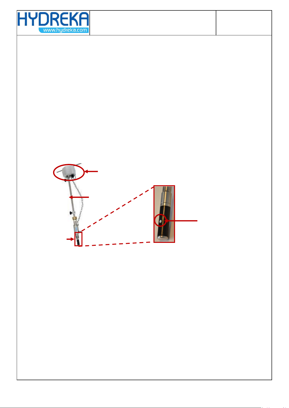
5.1.3 Step 3/3: Probe insertion .................................................................................................... 27
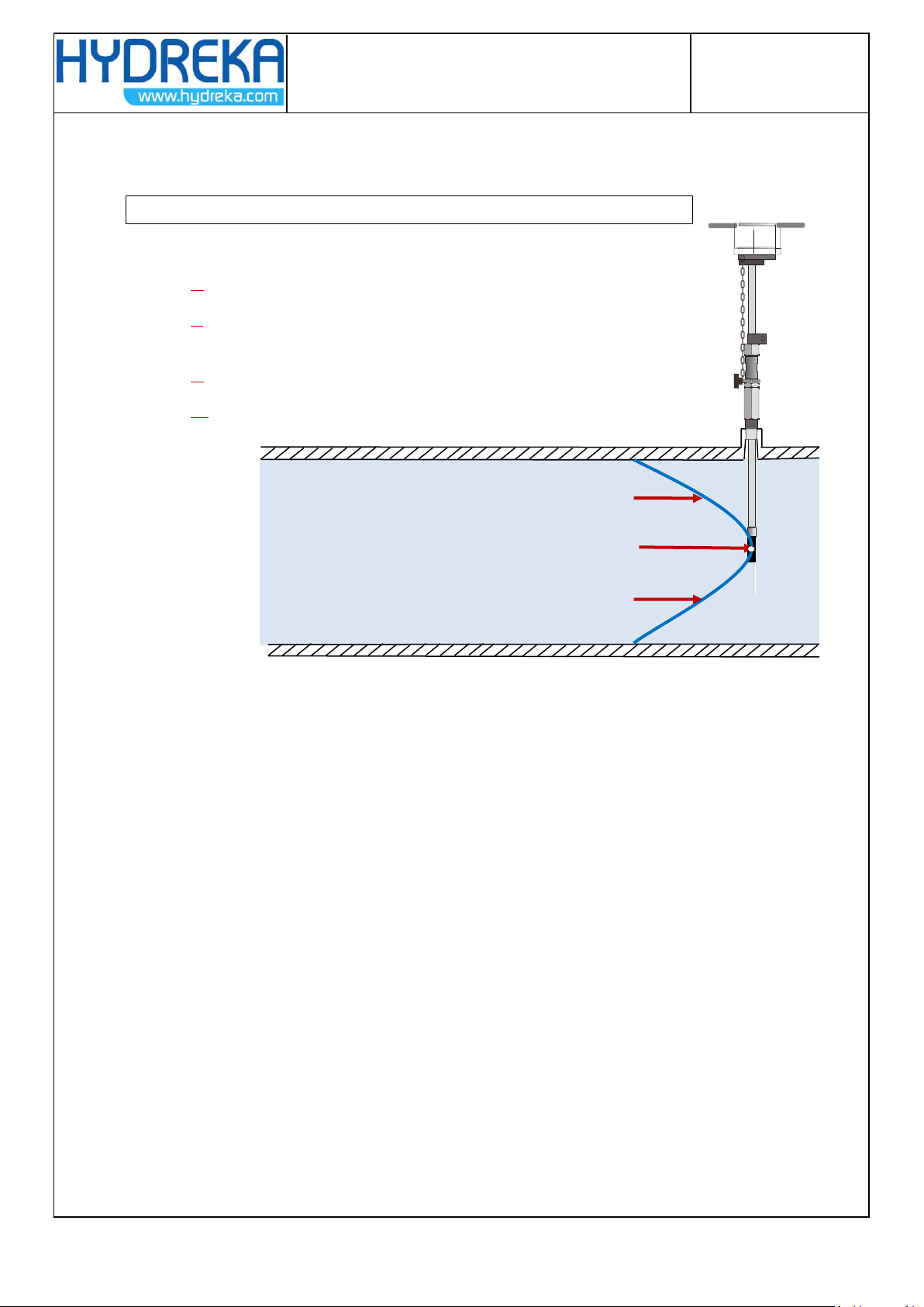
5.2 Method for installation at 1/8 .......................................................................................... 28
5.3 Aligning the guide bar with the direction of flow............................................................... 29
6INSTALLING THE PRESSURE CHANNEL ON A DATA RECORDER ................................... 30
7VIEWING MEASUREMENTS BY DISPLAY OR RECORDING............................................ 31
8INSTALLATION OF A DISPLAY .................................................................................... 32
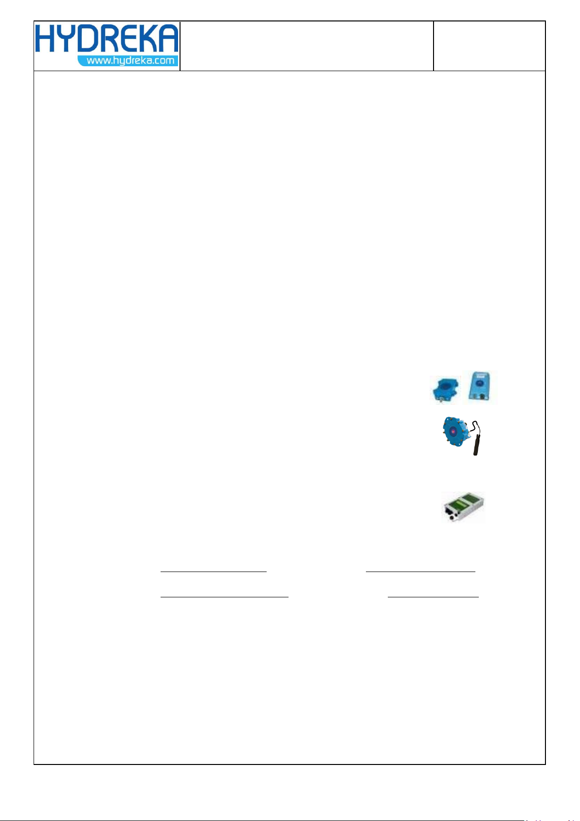
8.1 Preview of Displays .......................................................................................................... 32
8.2 Mounting the display unit on a wall.................................................................................. 33
8.3 Mode change of the HydrINS 2 and HydrINS 2 Mini probes................................................ 34
8.3.1 Equipment........................................................................................................................... 34
8.3.2 Removal............................................................................................................................... 34
8.3.3 Mode change....................................................................................................................... 36
8.4 Electrical power supply of Display A.................................................................................. 39
8.4.1 Internal power supply using 3.6 VDC lithium batteries ...................................................... 41
8.4.2 External power supply using 3.6 VDC lithium batteries...................................................... 41
8.4.3 Internal power supply using alkaline batteries................................................................... 42
8.4.4 External 9 to 28 VDC power supply connected to the internal terminals. ......................... 42
8.4.5 External power supply by military connector ..................................................................... 43
8.5 Electrical power supply of Display C.................................................................................. 43
8.6 Electrical power supply of Display and Recording Unit....................................................... 44
8.7 Wiring of the entities of the measurement chain............................................................... 45
8.8 Internal wiring ................................................................................................................. 48
8.8.1 Connections of the HydrINS probe to the Display terminal block ...................................... 48
8.8.2 Pulse output connections to the Display terminal block .................................................... 49
8.8.3 Wiring the 4-20 mA outputs to the terminal block of Display C ......................................... 50