Hydrel Paradox Series User manual

TO INSTALL:
1. Dig a hole to appropriate depth allowing for rough-in-section to
be secured to conduit.
INSTALLATION INSTRUCTIONS
12881 Bradley Ave
Sylmar,CA91342
Phone: 818-362-9465
Fax:818-362-6548
www.hydrel.com
©2007 Acuity Brands Lighting, Inc.
Rev. 11/28/07
INS-PDX7_REV0
NOTE: HYDREL RESERVES THE RIGHT TO MODIFY SPECIFICATION WITHOUT
NOTICE. Any dimension on this sheet is to be assumed as a reference
dimension: "Used for information purposes only. It does not govern
manufacturing or inspection requirements." (ANSI Y14.5-1973)
PARADOXSERIES
PDX7
Installation should be performed by a qualified
electrician in accordance with the National Electrical Code
and relevant local codes.
2. To install with door flush to finish
grade:
2a. Mount Rough-in-Section
(RIS) with flush pour shield
placed at finish grade.
Door Screws
Flush Pour Shield
Temporary Cover Plate
Rough-in-Section
(RIS)
Rough-in-
Section (RIS)
Rough-in-
Section (RIS)
Flush Pour Shield
Temporary
Cover Plate
Pour Screw
Finish
Grade
Door
Finish
Grade
Finish
Grade
Enlarged detail
with door
installed.
Enlarged detail
with temporary
cover plate and
flush pour
shield.
Rough-in-Section (RIS) before
pouring finish grade
Rough-in-Section (RIS) after
pouring finish grade

INSTALLATION INSTRUCTIONS
12881 Bradley Ave
Sylmar,CA91342
Phone: 818-362-9465
Fax:818-362-6548
www.hydrel.com
©2007 Acuity Brands Lighting, Inc.
Rev. 11/28/07
INS-PDX7_REV0
NOTE: HYDREL RESERVES THE RIGHT TO MODIFY SPECIFICATION WITHOUT
NOTICE. Any dimension on this sheet is to be assumed as a reference
dimension: "Used for information purposes only. It does not govern
manufacturing or inspection requirements." (ANSI Y14.5-1973)
PARADOXSERIES
PDX7
Installation should be performed by a qualified
electrician in accordance with the National Electrical Code
and relevant local codes.
3. To install with Rough-in-Section
(RIS) flush to finish grade:
3a. Remove flush pour shield
from Rough-in-Section (RIS).
3b.Re-attach temporary cover
plate onto Rough-in-Section
(RIS).
3c. Mount Rough-in-Section
with temporary cover plate
placed at finish grade.
Door Screws
Flush Pour Shield
Temporary Cover Plate
Rough-in-Section
(RIS)
Door Screw
Finish Grade
Temporary
Cover
Plate
Rough-in-
Section (RIS)
Rough-in-
Section (RIS)
Finish
Grade
Door
Finish
Grade
1/8”1/8”
1/8”1/8”
1/8”
Enlarged
detail with
temporary
cover plate.
Enlarged detail
with door
installed.
Rough-in-Section (RIS) before
pouring finish grade.
Rough-in-Section (RIS) after
pouring finish grade.

INSTALLATION INSTRUCTIONS
12881 Bradley Ave
Sylmar,CA91342
Phone: 818-362-9465
Fax:818-362-6548
www.hydrel.com
©2007 Acuity Brands Lighting, Inc.
Rev. 11/28/07
INS-PDX7_REV0
NOTE: HYDREL RESERVES THE RIGHT TO MODIFY SPECIFICATION WITHOUT
NOTICE. Any dimension on this sheet is to be assumed as a reference
dimension: "Used for information purposes only. It does not govern
manufacturing or inspection requirements." (ANSI Y14.5-1973)
PARADOXSERIES
PDX7
Installation should be performed by a qualified
electrician in accordance with the National Electrical Code
and relevant local codes.
CAUTION: When installing in organic mulch, surround rough-in section with approximately six
inches (15cm) of sand or other non-organic substance.
FINISH GRADE
REBAR
CONDUIT
CONDUIT
Install fixture flush
per step 2 / 3.
Secure rough-in
section to rebar to
prevent “floating.”
Install suitable thread
sealing compound
when connecting
conduit (side or
bottom entry).
4. For optional rebar anchoring: Secure rebar as shown
(rebar by others).

INSTALLATION INSTRUCTIONS
12881 Bradley Ave
Sylmar,CA91342
Phone: 818-362-9465
Fax:818-362-6548
www.hydrel.com
©2007 Acuity Brands Lighting, Inc.
Rev. 11/28/07
INS-PDX7_REV0
NOTE: HYDREL RESERVES THE RIGHT TO MODIFY SPECIFICATION WITHOUT
NOTICE. Any dimension on this sheet is to be assumed as a reference
dimension: "Used for information purposes only. It does not govern
manufacturing or inspection requirements." (ANSI Y14.5-1973)
PARADOXSERIES
PDX7
Installation should be performed by a qualified
electrician in accordance with the National Electrical Code
and relevant local codes.
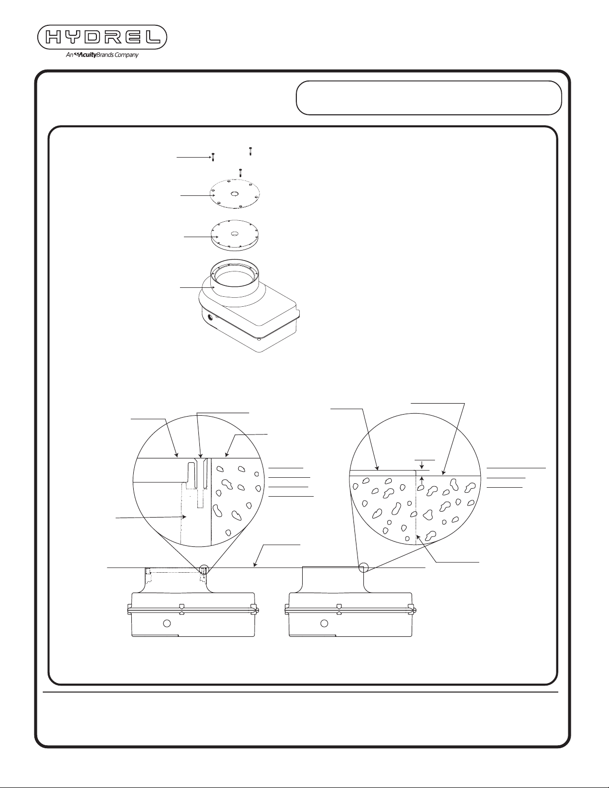
5. Remove temporary cover or tempo-
rary cover and flush pour shield.
6. Loosen junction box screw and re-
move lid.
IMPORTANT NOTE:
Do
NOT lose screw. Screw contains an
O-ring seal. It MUST be used to rein-
stall junction box lid in Step 9.
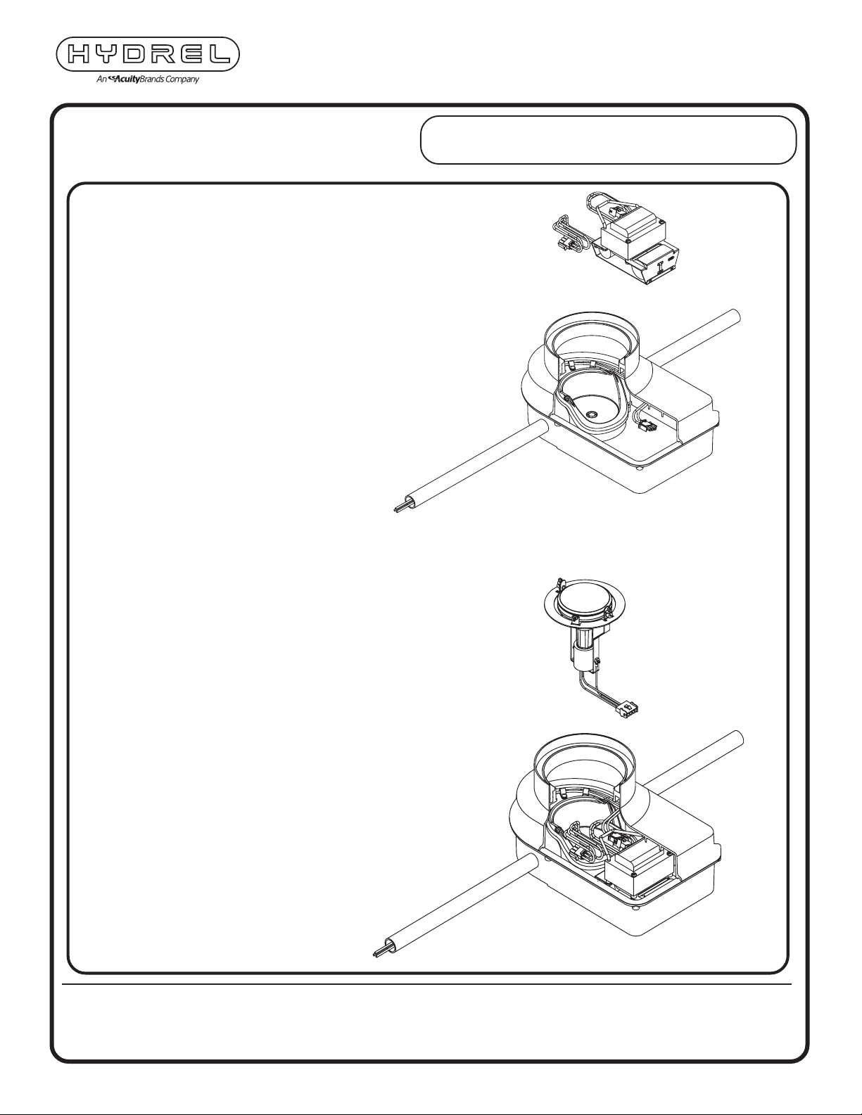
7. Connect 3/4” NPT conduit to junction box
(side or bottom entry). Seal conduit entry
using suitable thread sealing compound
to ensure conduit is watertight and to
prevent moisture penetration from con-
duit system.
8. Pull electrical supply conductors and
make wire splice in accordance with
NEC.
9. Reinstall junction box lid with
O-ring screw provided.
CAUTION: DO NOT OVER
TIGHTEN (20 IN-LBS OR 2 n-M).
▲

INSTALLATION INSTRUCTIONS
12881 Bradley Ave
Sylmar,CA91342
Phone: 818-362-9465
Fax:818-362-6548
www.hydrel.com
©2007 Acuity Brands Lighting, Inc.
Rev. 11/28/07
INS-PDX7_REV0
NOTE: HYDREL RESERVES THE RIGHT TO MODIFY SPECIFICATION WITHOUT
NOTICE. Any dimension on this sheet is to be assumed as a reference
dimension: "Used for information purposes only. It does not govern
manufacturing or inspection requirements." (ANSI Y14.5-1973)
PARADOXSERIES
PDX7
Installation should be performed by a qualified
electrician in accordance with the National Electrical Code
and relevant local codes.
10. Insert power supply module (HID Bal-
last, Fluorescent Ballast, LED Power
Supply, Low Voltage Transformer) into
housing. Connect using Hydrel pro-
vided quick connector to pre-installed
housing wiring.
11. Install lamp module. Connect to
modular power supply using
Hydrel provided quick connector.

INSTALLATION INSTRUCTIONS
12881 Bradley Ave
Sylmar,CA91342
Phone: 818-362-9465
Fax:818-362-6548
www.hydrel.com
©2007 Acuity Brands Lighting, Inc.
Rev. 11/28/07
INS-PDX7_REV0
NOTE: HYDREL RESERVES THE RIGHT TO MODIFY SPECIFICATION WITHOUT
NOTICE. Any dimension on this sheet is to be assumed as a reference
dimension: "Used for information purposes only. It does not govern
manufacturing or inspection requirements." (ANSI Y14.5-1973)
PARADOXSERIES
PDX7
Installation should be performed by a qualified
electrician in accordance with the National Electrical Code
and relevant local codes.
12. Adjust lamp/reflector assembly to
aim. Secure with locking/aiming
screws.
13. Install door lens assembly ensuring
screws are tight.
LAMP ADJUSTMENT DETAIL
1. Loosen two tilt screws.
2. Tilt lamp.
3. Tighten two
tilt screws.
4. Lock rotational ring screw.
This manual suits for next models
1
Table of contents
Other Hydrel Lighting Equipment manuals