Hydro International Up-Flo User manual

Operation and Maintenance Manual
Up-Flo® Filter
Filtration System for Stormwater Treatment Stormwater Solutions
Turning Water Around ...®

Up-Flo®Filter Operation and Maintenance Manual
Hydro International (Stormwater), 94 Hutchins Drive, Portland ME 04102
Tel: (207) 756-6200 Fax: (207) 756-6212 Web: www.hydro-int.com
Table of Contents
3 Up-Flo®Filter
- Overview
- General Product Description
-TypicalCongurations
- Maintenance Services
4 Operation
- Introduction
- Pollutant Capture
- Reduced Clogging
-OverowProtection
- Good Housekeeping & Best Practices
- Damage Due to Lack of Maintenance
5 Inspection & Maintenance
- Overview
- First-Year Monitoring
- Inspection
- Maintenance Activities Not Requiring Man Entry - Floatables, Oil and Sump Cleanout
- Maintenance Activities Requiring Man Entry - Replacement of Media Packs and Drain Down Filter
- Solids Disposal
13 Up-Flo®Filter Installation Log
14 Up-Flo®Filter Inspection Log
16 Up-Flo®Filter Maintenance Log
17 StormwaterBMPMaintenanceCerticationProgram
COPYRIGHT STATEMENT:Thecontentsofthismanual,includingthedrawingsandspecicationscontainedhereinorannexedhereto,areintendedfor
the use of the recipient to whom the document and all associated information are directed. Hydro International plc owns the copyright of this document
(includinganydrawingsorgraphics),whichissuppliedincondence.Itmustnotbeusedforanypurposeotherthanthatforwhichitissuppliedandmust
not be reproduced, in whole or in part, stored in a retrieval system or transmitted in any form or by any means without prior permission in writing from
Hydro International plc. Up-Flo®FilterisatrademarkedltrationdeviceofHydroInternationalplc.ApatentcoveringtheUp-Flo®Filter has been granted.
DISCLAIMER: Information and data contained in this manual is exclusively for the purpose of assisting in the operation and maintenance of Hydro
International plc’s Up-Flo®Filter. No warranty is given nor can liability be accepted for use of this information for any other purpose. Hydro International plc
haveapolicyofcontinuousproductdevelopmentandreservetherighttoamendspecicationswithoutnotice.
IMPORTANT -ORDER REPLACEMENTPARTSFORMAINTENANCE-IMPORTANT
Annual maintenance requires replacement of the Media Packs and the Drain Down Filter. Contact Hydro International to order
replacements. Allow 2-4 weeks for delivery.
OfcehoursMondaythruFriday8:00A.M.to5:00P.M.EST
Tollfree:1-800-848-2706
Phone: 207-756-6200
Fax: 207-756-6212
Email: [email protected]
Page | 2

Up-Flo®Filter Operation and Maintenance Manual
The Up-Flo®Filterisamodularhigh-ratestormwaterltrationdevice.Asshownbelow,itistypicallyinstalledintoa4-ftdiametercatch
basin structure. Each Filter Module has a screen and support bracket that is attached to the concrete manhole and each contains a Media
Pack that includes Flow Distribution Media and two Media Bags (Fig.1). Modules can attach to each other to form a “ring” of up to six
modules. Up to two of the modules are attached to an Outlet Module that has a Bypass Hood and Drain Down Filter. The modular design
canbesuppliedindifferentcongurationsdependingontheapplicationasshowninthefollowingillustrations.
AnupwardowpaththroughtheFilterModulesallowsstormwatertobescreenedandltered.Inadditiontothescreeningandltering
processes,grosspollutantswillalsosettleintothesumporoattothesurfaceofthewaterheldwithinthemanhole.Thestandardunits
are supplied with a 3-ft (0.9m) sump to allow for sediment and gross pollutant accumulations between maintenance intervals.
The following manual describes the operation of the Up-Flo®Filter and provides general maintenance requirements that will ensure
thelterwillcontinuetooperateandperformasintended.Ingeneral,aminimumoftwoinspectionsarerequiredperyeartomonitor
sedimentandgrosspollutantaccumulations.InordertoachieveanannualTSSremovalrateof80%fortheUp-Flo®Filter, the minimum
maintenancefrequencyspeciedinthemaintenancesectionforreplacementoftheMediaPackandremovalofaccumulatedsediment
from the sump is mandatory.
HydroInternationaloffersrecommendationsforcertiedmaintenancecontractors.Itishopedthatownerswilltakeadvantageofthis
serviceasthesecontractorshavebeentrainedandcertiedtoensurethatmaintenancewillbeperformedproperly.Shouldtheowner
choose to conduct maintenance procedures themselves, it is recommended that Hydro International be contacted to discuss the following
proceduresandconsidercontractingarepresentativefromHydroInternationalfortherstmaintenancecycle.
Seepage17formoreaboutHydroInternational’sStormwaterBMPMaintenanceContractorCerticationProgram.
Product Overview
Page | 3
Up-Flo® Filter Components
1. Inlet Grate
2.SiphonicBypassHoodwithFloatablesBafe
3. Filter Module
4. Outlet Module
5. Media Pack
6. Angled Screen
7. Drain Down Filter Assembly (refer to Fig.10 for closer view)
8.Sump
8
6
5
3
4
2
7
1
Fig.1 The components of the Up-Flo®Filter.

Up-Flo®Filter Operation and Maintenance Manual
Hydro International (Stormwater), 94 Hutchins Drive, Portland ME 04102
Tel: (207) 756-6200 Fax: (207) 756-6212 Web: www.hydro-int.com
Operation
Introduction
The Up-Flo® Filter operates on simple uid hydraulics. It is self-
activating, has no moving parts, no external power requirements and
is fabricated with durable non-corrosive components. Personnel
are not required to operate the unit and maintenance is limited to
periodicinspections,sedimentandoatablesremoval,MediaPack
replacement and Drain Down Filter replacement.
Pollutant Capture
The Up-Flo®Filter is designed to operate as a “treatment train” by
incorporating multiple treatment technologies into a single device.
Trash and gross debris are removed by sedimentation and screening
beforetheyareintroducedtotheltrationmedia,preventingsurface
blindingoftheltermedia.TheUp-Flo®Filter is a wet-sump device.
Between storm events, oil and oatables are stored on the water
surface separate from the sediment storage volume in the sump (see
Fig.2).Thehigh-capacitybypasssiphonactsasaoatablesbafeto
preventwashoutofcapturedoatablepollutantsduringhighintensity
events.
Reduced Clogging
The Up-Flo®Filter has been designed to minimize the occurrence
of clogging and blinding. The Up-Flo®Filter employs a unique Drain Fig.2 Pollutants captured in the Up-Flo®Filter.
Outlet
Module
with
Bypass
Hood
Filter
Module
Floating
Debris
Settled
Solids
Drain
Down
Filter
Angled
Screen
Page | 4
DownFilterthatallowsthewaterlevelinthechambertodropbelowtheltermediabetweenevents.TheDrainDownFiltermechanism
createsareverseowthatushescapturedpollutantsoffthesurfaceoftheMediaBag,helpingtopreventblinding.Byallowingthewater
to drain out, the Drain Down Filter also reduces the weight of the Media Bags. This makes the bags easier and safer to remove during
maintenance operations.
OverowProtection
TheAngled Screens are designed to prevent ragging and blinding. The Angled Screens are situated below the Filter Modules, sheltering
themfromthedirectpathoftheinuent.Coarsedebrissettlesinthesumpbeforetherunoffowsupthroughthescreens,protecting
themfromblinding.Intheunlikelyeventofablockage,thehighcapacitysiphonicBypassHoodisdesignedtoconveyhighenoughow
tominimizetheriskoflargestormcreatingupstreamooding.
Good Housekeeping & Best Practices
Good housekeeping practices upstream of the Up-Flo®Filter can signicantly extendMediaBag life. Forexample, sweeping paved
surfaces, collecting leaves and grass trimmings, and protecting bare ground from erosion will reduce loading to the system. Media Packs
should not be installed in the Filter Modules until construction activities are complete and site stabilization is effective.
Damage Due to Lack of Maintenance
Delayed maintenance would result in clogged Media Bags and/or blinded Angled Screens. In that situation, the Up-Flo®Filter would go
intobypassandtherewouldbenotreatmentoftheincomingstormwater.BecausetheBypassWeircaneasilyconveyalloftheowto
the Outlet Module, there would be no lasting damage to the system. Replacement of the Media Bags and removal of sediment from the
sump would restore the Up-Flo®Filtertoitsoriginaltreatmentefciency.Establishingandadheringtoaregularmaintenanceschedule
ensures optimal performance of the system.

Up-Flo®Filter Operation and Maintenance Manual
Inspection & Maintenance
Overview
The Up-Flo®Filter protects the environment by removing a wide range of pollutants from stormwater runoff. Periodic removal of these
captured pollutants is essential to the proper functioning of the Up-Flo®Filter.
Maintenance activities can be categorized as those that may be performed from outside the Up-Flo®vessel and those that are performed
insidethevessel.Maintenanceperformedfromoutsidethevesselincludesremovalofoatablesandoilsthathaveaccumulatedonthe
water surface and removal of sediment from the sump. Maintenance performed inside the vessel includes removal and replacement
of Media Bags, Flow Distribution Media and the Drain Down Filter. A vactor truck is required for removal of oils, water, sediment, and
tocompletelypumpoutthevesseltoallowformaintenanceinside.OSHAConnedSpaceEntryproceduresmustbefollowedwhen
entering the Up-Flo®vessel.
The Up-Flo®Filter design allows for easy and safe inspection, monitoring and clean-out procedures. It has a wide central opening
between the Filter Modules for easy and comfortable access to all of the components (see Fig.3). Completion of all the maintenance
activities for a typical manhole Up-Flo®Filtertakeslessthanonehour.Inthecaseofinspectionandoatablesremoval,avactortruckis
not required. Otherwise, a vactor truck is normally required for oil removal, removal of sediment from the sump, and replacement of the
Media Packs and Drain Down Filter. In most cases, entry into the Up-Flo®Filter vessel is required for replacement of the Media Packs
andDrainDownFilter,andOSHAConnedSpaceEntryprocedureswillhavetobefollowed.
a. Manhole b. Vault
Fig.3 The Up-Flo® Filter is installed in a) 4-ft (1.2m) round manholes or b) in rectangular precast vaults. Both congurations have a wide central opening
in the Up-Flo®Filter.
Page | 5
Maintenanceactivitiesincludeinspection,oatablesremoval,oilremoval,sedimentremoval,MediaPackreplacement,andDrainDown
Filter replacement. The minimum required frequency for replacement of the Media Pack is annually, whereas the minimum required
frequency for removal of accumulated sediment from the sump is dependent on the Up-Flo®Filterconguration.Congurationswitha
larger sediment storage volume per module will require less frequent removal of accumulated sediment. Regardless, whenever sediment
depth in the sump is found to be greater than 16 inches, sediment removal is required.

Up-Flo®Filter Operation and Maintenance Manual
Hydro International (Stormwater), 94 Hutchins Drive, Portland ME 04102
Tel: (207) 756-6200 Fax: (207) 756-6212 Web: www.hydro-int.com
First Year Inspection and Maintenance
Thefrequencyofinspectionandmaintenancecanbedeterminedintheeldafterinstallation.Thefrequencyofongoingmaintenance
needs is based on site characteristics such as contributing area, types of surfaces (e.g., paved and/or landscaped), site activities (e.g.,
short-term or long-term parking), and other site maintenance (e.g., sanding and sweeping). At a minimum, inspection and maintenance
shouldbeconductedatintervalsofnomorethansixmonthsduringtherstyearofoperation.Maintenancepersonnelshouldobserve
andrecordpollutant accumulations duringtherst year ofservicein order to benchmarkthemaintenance intervals thatwilllater be
established for the site. Pollutant accumulations should be measured or monitored using the following procedures:
• Measurementofsedimentdepthinthesump:Aminimumof8inches(20cm)shouldseparatetheDrainDownFilterinletfromstored
sediment in the sump in order to minimize sediment migration into the Drain Down Filter. Asimple probe, such as the Sludge-Judge®,
can be used to determine the depth of the solids in the sump. In a typical 4-ft
(1.2m) diameter manhole installation, the sediment depth should be no more
than 16 inches (41 cm).
• Maintenance personnel should then enter the structure, remove the Media
Pack from one of the Filter Modules, and weigh the Media Bags. Media Bags
withawetweightofapproximately40lbs(18kg)ormoreareanindication
thattheltermediahasbecomefullandthattheMediaPacksinallofthe
Filter Modules will require replacement (Fig.4). Minimum ltration rate is
generally reached when the Media Bags have accumulated approximately 20
lbs (9 kg) of sediment. Determining the amount of accumulated sediment will
be accomplished by removing both of the Media Bags from one of the Media
Packs and weighing the bags separately. Since a new Media Bag weighs
approximately 30 lbs (14 kg) wet, the difference in weight will approximately
equal the weight of solids that have accumulated in the bag. A spent Media
Bag weighs approximately 50 lbs (23 kg) wet.
• Measurement of oil layer on water surface: Since water in the Up-Flo®vessel
drains down to an elevation below the bottom of the Filter Modules when the
system is idle, the amount of accumulated oil must be minimized so that oil is
notentrainedintheMediaPackwhenstormwaterbeginstollthevesselat
the start of a storm event. Oil accumulation should be limited to 1.5 inches (4
cm) or less. Probes can be used to measure oil thickness.
• Monitoring for Drain Down Filter clogging: The water level in the Up-Flo®
Filter should be monitored to ensure that the Drain Down Filter is operating
properly. The Drain Down Filter is designed to lower the water level in the Up-
Flo®vessel to an elevation below the bottom of the Filter Modules between
storm events. Periodically conduct an inspection one to two days after a
stormeventduringtherstyearofoperation.Approximately36hoursaftera
1-in (2.5-cm) rainfall, the water level inside the vessel should have dropped
to a point where it is equal with the base of the Filter Modules. If the water
level has not reached that point, then the Drain Down Filter has either become clogged or blinded by trash or debris (Fig.5 a and b).
If there is no evidence of trash or debris around the Drain Down Filter inlet, then it has likely become clogged with particles.
• Monitoring for slime and debris covering the Flow Distribution Media orAngled Screens: After removal of the Media Bags, the bottom
Flow Distribution Media should be removed and inspected to determine if it is coated with slime or debris. Similarly, the Angled
Screen should be inspected for blockages and ragging.
Page | 6
Fig.4 a) A new Media Bag of Hydro Filter Sand. b) A spent
media bag of Hydro Filter Sand.
a.
b.

Up-Flo®Filter Operation and Maintenance Manual
• Monitoringforoatablesonthewatersurface:Similartooil,theamountofaccumulatedoatablesmustbeminimizedtoprevent
trashandloosedebrisfrombecomingtrappedontheAngledScreenswhenstormwaterbeginstolltheUp-Flo®vessel at the start
ofastormevent.Visualinspectionisadequatetodeterminetheamountofoatables.Floatablesshouldberemovedbeforethey
form a mat on the surface of the water.
The solids loading rate in the sump will be calculated by measuring the sediment depth in the sump and dividing the depth by the
correlating interval of time since the sump was last cleaned. Similarly, starting with fresh Media Bags, the solids loading rate in the Media
Packs will be calculated by weighing the Media Bags and dividing the weights by the correlating interval of time since they were installed.
The wet weight of the heaviest bag will be used to determine the loading rate. As previously mentioned, a spent Media Bag weighs
approximately 50 lbs (23 kg) wet. The spent Media Bag weight estimate was based on calculations of sediment loading in an Up-Flo®
Filter that was run to exhaustion during laboratory testing.
The rate of oil accumulation will be calculated by measuring the thickness of the oil layer and dividing the thickness by the correlating
intervalof timesincethe sumpwas lastcleaned. Ordinarily,oil thicknesswillnot bemeasurable unlessa spillhasoccurred. Consequently,
any oil will typically be removed along with water when cleaning the sump.
Monitoring the Drain Down Filter for clogging, monitoring the Flow Distribution Media and Angled Screens for slime and debris, and
monitoringtheaccumulationofoatableswillprovideanestimateofhowlongtheUp-Flo®Filter can operate before its performance can
become impaired by one of these factors.
Routine Inspection and Maintenance
Aftercompletionoftherstyearofoperation,determiningandthenfollowingtheestablishedinspectionandmaintenanceintervalswill
keeppollutantloadingswithintheirrespectivelimits.Removalofoilsandoatables,replacementoftheDrainDownFilter,replacement
of Flow Distribution Media (see Fig.9, pg 11), and cleaning of Angled Screens will occur at the same frequency as cleaning of the sump
andreplacementofMediaBagsunlesstherstyearofoperationindicatesotherwise.Keepingtotheestablishedmaintenanceintervals
willkeeptreatmentowratesat,orabove,thedesignowrate.Typically,annualmaintenanceisadequate.
In addition to scheduled maintenance, occasional checks for Up-Flo®Filter clogging can be performed by removing the manhole cover
duringastorm,monitoringthewaterlevelinthemanholeorvault,anddeterminingwhetherthelterisinbypass.Aproperly-sizedlter
(on-lineoroff-line)thatisinbypassduringastormthatisproducingrunoffat,orbelow,thelter’sdesignltrationrateneedsmaintenance.
Page | 7
Fig.5 a) The water level in a properly functioning Up-Flo®Filter will drain down to the base of the Filter Modules. b) When the Drain Down Filter becomes
clogged, the base of the Filter Modules will be submerged in standing water. Note, above right, that the Drain Down Filter is submerged in standing water.
a. b.

Up-Flo®Filter Operation and Maintenance Manual
Hydro International (Stormwater), 94 Hutchins Drive, Portland ME 04102
Tel: (207) 756-6200 Fax: (207) 756-6212 Web: www.hydro-int.com
Routine Inspection
Inspection is a simple process that requires monitoring pollutant
accumulations. Maintenance crews should be familiar with the
Up-Flo®Filter and its components prior to inspection.
Scheduling
• Inspection may be conducted during any season of the year
but should occur shortly after a predicted rainfall to ensure
components are operating properly.
Recommended Equipment
• SafetyEquipmentandPersonalProtectiveEquipment(trafc
cones, work gloves, etc.)
• Scale to measure the weight of the Media Bags
• Crow bar to remove grate or lid
• Pole with skimmer or net
• Sediment probe (such as a Sludge-Judge®)
• Hydro International Up-Flo®Filter Maintenance Log
• Trashbagsforremovedoatables
Routine Inspection Procedures
1. Set up any necessary safety equipment (such as trafc
cones) to provide access to the Up-Flo®Filter. Safety equip-
ment should notify passing pedestrian and road trafc that
work is being done.
2. Remove the grate or lid to the manhole or vault.
3. Without entering the vessel, look down into the chamber to
inspect the inside and to determine whether the high-water
level indicator has been activated. Make note of any irregu-
larities. See Fig.6 for a typical Inspection View.
4. Without entering the vessel, use the pole with the skimmer net
toremoveoatablesandloosedebrisfromthechamber.
5. Using a sediment probe such as a Sludge-Judge®, measure
the depth of sediment that has collected in the sump of the
vessel.
Maximum sediment depth is 16 inches (41 cm).
6. If the high-water level indicator has been activated after two
consecutive storms, remove the Filter Module lid by turning
the cam latch and remove the Filter Media Pack (refer to page
11 Replacement Procedures). Weigh the Media Bags from
one or two modules. Media Bags should be replaced if the
wetweightexceeds40lbs(18kg).
7. On the Maintenance Log provided by Hydro International, re-
cord the date, unit location, estimated volume of oatables
and gross debris removed, and the depth of sediment mea-
sured. Also note any apparent irregularities such as damaged
components or a high standing water level (see Fig.6 for the
standard standing water level).
8. Securely replace the grate or lid.
9. Remove safety equipment.
10. ContactHydroInternationalat(800)848-2706todiscussany
irregularities noted during inspection.
Bypass siphon sits evenly on Outlet Module.
Standing water level is no higher than the base of the Filter
Module. The Drain Down Filter will be visible if the water level
is correct.
Filter Module Lids are closed.
Fig.6 Inspection view of the Up-Flo® Filter.
Page|8

Up-Flo®Filter Operation and Maintenance Manual
Fig.7 Sediment is removed from the sump with a vactor hose. Man entry is not required for this step.
Routine Maintenance
Maintenance activities are grouped into two categories:
• Activities Not Requiring Man Entry Into the Up-Flo®Filter
Theseactivitiesincludeoatablesremoval,oilremovaland
removal of sediment from the sump.
• Activities Requiring Man Entry Into the Up-Flo®Filter
Media Pack replacement and Drain Down Filter replacement.
Maintenance intervals are determined from monitoring the Up-Flo®
Filterduringitsrstyearofoperation.Dependingonthesite,some
maintenance activities may have to be performed on a more frequent
basisthanothers.Inthecaseofoatablesremoval,avactortruck
is not required. Floatables and loose debris can be netted with a
skimmer and pole.
A vactor truck is normally required for oil removal, removal of sedi-
ment from the sump, and to dewater the vessel for replacement of
the Media Packs and Drain Down Filter (Fig.7). All inspection and
maintenance activities would be recorded in an Inspection and Main-
tenance Log.
Completion of all the maintenance activities for a typical 4-ft (1.2m)
diameter manhole installation takes less than one hour. Approxi-
mately 360 gallons of water and up to 0.6 yd3(0.5 m3) of sediment
may be removed in the process. In an installation equipped with
six Filter Modules, 12 Media Bags (2 bags per module) would be
removed and replaced. Assuming a spent Media Bag weight of 50
lbs (23 kg), up to 600 lbs (272 kg) of spent Media Bags would be
removed. All consumables, including Media Bags, Flow Distribution
Media, and replacement Drain Down Filters are supplied by Hydro
International.
The access port located at the top of the manhole provides unob-
structed access for a vactor hose and/or skimmer pole to be lowered
to the base of the sump.
Page | 9
Maintenance Activities Not Requiring Man Entry
Theseactivitiesincludeoatablesremoval,oilremovaland
removal of sediment from the sump.
Scheduling
• Floatables and sump cleanout may typically be done during
any season of the year - before and after rainy season
• Floatables and sump cleanout should occur as soon as
possible following a contaminated spill in the contributing
drainage area
Recommended Equipment
• SafetyEquipment(trafccones,etc)
• Crow bar to remove grate or lid
• Polewithskimmerornet(ifonlyoatablesarebeingremoved)
• Sediment probe (such as a Sludge-Judge®)
• Vactortruck(exiblehosepreferred)
• Pressure nozzle attachment or other screen-cleaning device
• Hydro International Up-Flo®Filter Maintenance Log

Up-Flo®Filter Operation and Maintenance Manual
Hydro International (Stormwater), 94 Hutchins Drive, Portland ME 04102
Tel: (207) 756-6200 Fax: (207) 756-6212 Web: www.hydro-int.com
Maintenance Procedures Not Requiring Man Entry:
Floatables, Oil and Sediment Clean Out
1. Set up any necessary safety equipment (such as traf-
c cones) around the access of the Up-Flo®Filter. Safety
equipmentshouldnotifypassingpedestrianandroadtrafc
that work is being done.
2. Remove the grate or lid to the manhole or vault.
3. Without entering the vessel, look down into the chamber to
inspect the inside. Make note of any irregularities.
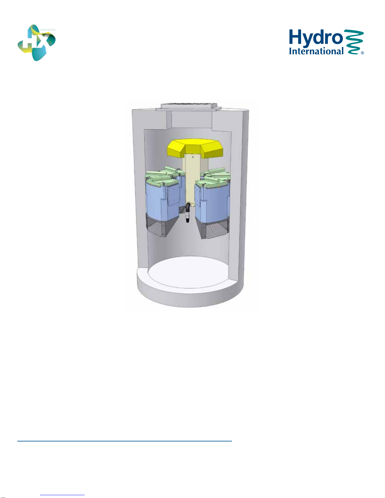
4. If the standing water level in the sump is above the base of
theFilter Modules(seeFig.8),tugthePullChain(s) tore-
lease the Drain Down Filter plug(s). Allow the excess water
to drain out of the chamber.
5. Use the skimmerpoletottheDrainDownFilterplugback
into the open port.
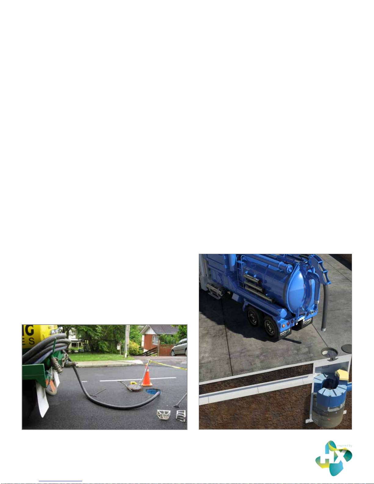
6.Once all oatables and oil have been removed, drop the
vactor hose to the base of the sump. Vactor out the sedi-
mentandgrossdebrisfromthesumpoor.Upto0.3yd3
(0.2 m3) of sediment and 360 gallons (1,363 L) of water will
be removed from a typical manhole Up-Flo®Filter during
this process.
7. Retract the vactor hose from the vessel.
8.InspecttheAngledScreensforblockagesandragging.If
present, remove the obstruction or ragging materials from
the surface using a hose or other screen-cleaning device.
9. On the Maintenance Log provided by Hydro International,
record the date, unit location, estimated volume of oata-
bles, oils, and gross debris removed, and the depth of sedi-
ment measured. Note any apparent irregularities such as
damaged components or blockages.
10. Securely replace the grate or lid. Remove safety equip-
ment.
11. Dispose of sediment and gross debris following local regula-
tions.
12. Dispose of oil and sump water at a licensed water treatment
facility or following local regulations.
13. Contact Hydro International at (800) 848-2706 to discuss
any irregularities noted during cleanout.
Maintenance Activities Requiring Man Entry
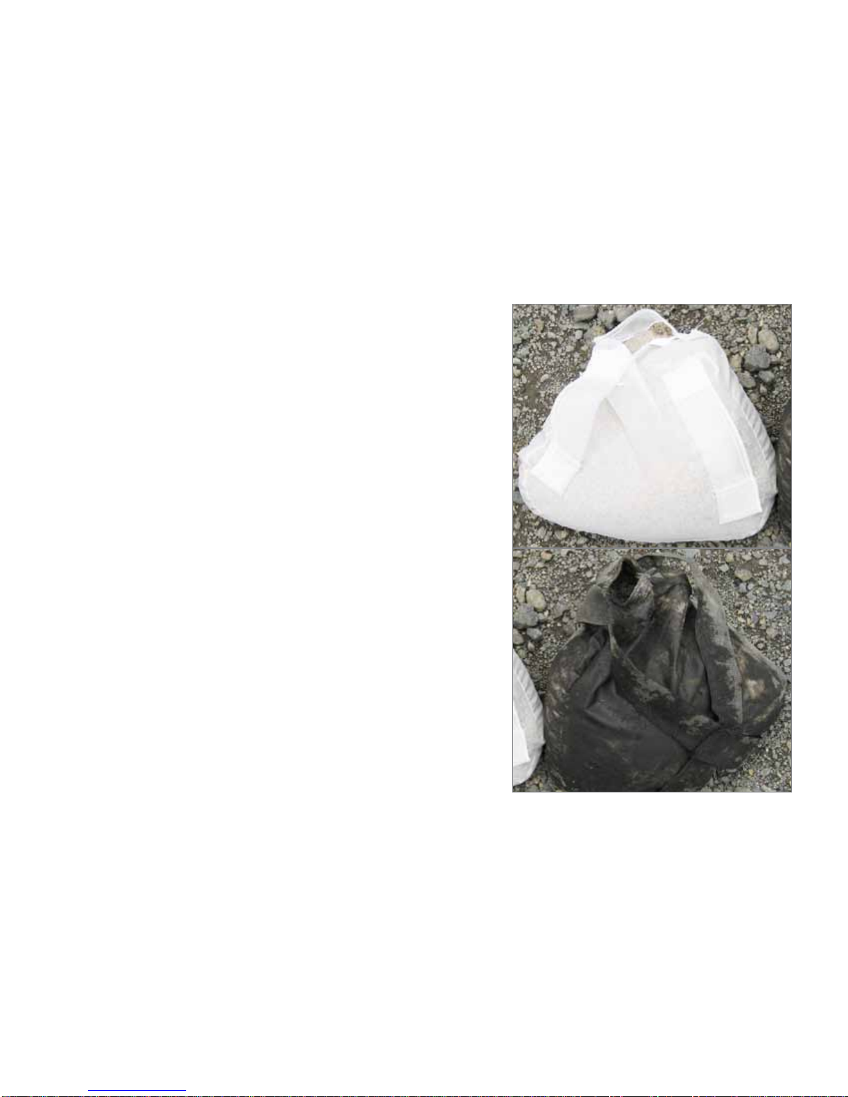
These activities include replacement of the Media Packs and
Drain Down Filter.
Unless the Up-Flo®Filter has been installed as a very shal-
lowunit,itisnecessarytohaveanOSHA-connedspaceentry
trained person enter the vessel to replace Media Packs.
The access port located at the top of the manhole or vault pro-
vides access to the Up-Flo®vessel for maintenance personnel
to enter the vessel and remove and replace Media Packs. The
same access would be used for maintenance personnel working
fromthesurfacetonetorskimdebrisandoatablesortovactor
out sediment, oil, and water. Unless the Up-Flo®Filter has been
installedinaveryshallowconguration,itisnecessarytohave
personnelwithOSHAConnedSpaceEntrytrainingperforming
the maintenance that occurs inside the vessel.
Scheduling
• Call Hydro International to order replacement Media Packs
and Drain Down Filter prior to scheduling maintenance.
• Because Media Pack replacement requires entry into the
Up-Flo®chamber, maintenance events should be scheduled
during dry weather.
• Media Pack replacement should occur immediately after a
contaminated spill in the contributing drainage area.
7
Page | 10
Fig.8 Cutaway view of the Filter Module

Up-Flo®Filter Operation and Maintenance Manual
Recommended Equipment
• SafetyEquipment(trafccones,etc.)
• Crow bar to remove grate or lid
• Pole withskimmerornet(ifoatablesremovalisnottobe
done with vactor hose)
• Sediment probe (such as a Sludge-Judge®)
• Vactortruck(exiblehosepreferred)
• OSHAConnedSpaceEntryEquipment
• Up-Flo®Filter Replacement Media Packs (available from
Hydro International)
• Hydro International Up-Flo®Filter Maintenance Log
• Screwdriver(athead)
• Replacement Drain Down Filter components supplied by
Hydro International
Maintenance Procedures Requiring Man Entry:
Media Pack and Drain Down Filter Replacement Procedures
1. Follow Floatables and Sump Cleanout Procedures, 1 – 13.
2. FollowingOSHAConnedSpaceEntryprocedures,enterthe
Up-Flo®Filter Chamber.
3. Open the Filter Module by turning the three cam latches on
the front and sides of the module. Remove the lid 1to gain
access to the Media Pack (Fig.9).
4. Remove and discard the spent Media Pack. The Media Pack
contents include:
•Atoplayerofgreen 2Flow Distributing Media.
•Two(2)MediaBags 3equipped with nylon handles.
•Abottomlayerofgreen 2Flow Distributing Media.
5. Insert a new Media Pack, supplied by Hydro International.
•First,insertabottomlayerofgreenFlowDistributing
Media. Be sure that the media sits snugly and level at
the bottom of the Filter Module.
•Next,inserttherstoftwo(2)replacementMedia
Bags. Smooth the bag out with your hands to make
sure that the bag extends snugly to the walls and
corners of the Filter Module.
•InsertthesecondMediaBag,followingthe
same procedure.
Fig.9 The Filter Module houses the Media Restraint and the Media Pack.
1. Filter Module Cover and Media Restraint
2. Flow Distributing Media
3. Filter Media Bags
4. Replaceable Media Pack
5. Cam Latch
6. Conveyance Channel
7. Filter Module
8.SupportBracket/AngledScreen
5
7
1
3
4
2
6
8
2
Page | 11

Up-Flo®Filter Operation and Maintenance Manual
Hydro International (Stormwater), 94 Hutchins Drive, Portland ME 04102
Tel: (207) 756-6200 Fax: (207) 756-6212 Web: www.hydro-int.com
•InsertthetoplayerofgreenFlowDistributingMedia.
Besurethatthepiecetssnuglyagainstthewallsand
corners of the Filter Module.
•Putthelidonandsecurethethreelatches.Checkto
make sure that the latches are closed properly.
6. Use a screwdriver to unscrew the Drain Down Filter from the
face of the Outlet Module (see Fig.10). DO NOT DISCARD
THIS PIECE.
7. Install new Drain Down Filter supplied by Hydro International.
8. Exit the Up-Flo®Filter chamber and securely replace the grate
or lid.
9. On the Maintenance Log provided by Hydro International,
recordthedate,unitlocation,estimatedvolumeofoatables,oil
andgross debrisremoved, andthe depthof sedimentmeasured.
NotethenumberofMediaPacksreplaced. Noteanyirregularities
such as damaged components or blockages.
10. Remove safety equipment.
11. Disposeofspentmediapacksatyourlocallandll,following
local regulations.
12. Return the spent Drain Down Filter to Hydro International.
13. Contact Hydro International to discuss any irregularities
noted during annual maintenance.
Maintenance at a Glance
Activity Frequency
Inspection -Regularlyduringrstyearofinstallation
-Every6monthsaftertherstyearofinstallation
Floatables/Oils Removal - Twice per year or as needed
- Following a contaminated spill in the drainage area
Sediment Removal - Every six to 12 months, depending on the Up-Flo®FilterConguration
-ThemaximumallowablesedimentdepthinanyUp-FloFiltercongurationis16inches(41cm)
- Following a contaminated spill in the drainage area
Media Pack Replacement
- Once per year
- Replacement is required anytime inspection reveals that the high-water level indicator has been
activated after two consecutive storms and the subsequent weighing of the Media Bags shows a
wet weight greater than 40 lbs
- Following a contaminated spill in the drainage area
Drain Down Filter Replacement
- Once per year with Media Pack replacement
- Replacement is required anytime inspection reveals that the water level inside the vessel has
not reached a level equal with the base of the Filter Modules approximately 36 hours after a
1-inch (2.5 cm) rainfall
-Asneeded,intheeventofcontinuousbaseowconditions
Fig.10 The Drain Down Filter.
2
31. Drain Down Filter
2. Drain Down Plug
3. Pull Chain for Drain Down
1
Page | 12
Solids Disposal
Sediment,oatables,grossdebris,andspentMediaBagscangenerallybedisposedofatthelocallandllinaccordancewithlocalregula-
tions. The toxicity of the residues captured will depend on the activities in the contributing drainage area, and testing of the residues may
be required if they are considered potentially hazardous.
Sump water can generally be disposed of at a licensed water treatment facility but the local sewer authority should be contacted for
permissionpriortodischargingtheliquid.Signicantaccumulationsofoilremovedseparatelyfromsumpwatershouldbetransported
to a licensed hazardous waste treatment facility for treatment or disposal. In all cases, local regulators should be contacted about
disposal requirements.

Up-Flo®Filter Operation and Maintenance Manual
Page | 13
Up-Flo®Filter Installation Log
SITE REFERENCE NAME OR NUMBER FOR THIS UP-FLO®FILTER LOCATION:
SITE NAME:
SITE LOCATION:
OWNER: SITE CONTRACTOR:
CONTACT NAME: CONTACT NAME:
COMPANY NAME: COMPANY NAME:
ADDRESS: ADDRESS:
TELEPHONE: TELEPHONE:
FAX: FAX:
INSTALLATION DATE: / /
CONFIGURATION (CIRCLE ONE): MANHOLE VAULT SYSTEM
TOTAL NUMBER OF UP-FLO®FILTER MODULES: _________________
Hydro International (Stormwater), 94 Hutchins Drive, Portland ME 04102
Tel: (207) 756-6200 Fax: (207) 756-6212 Web: www.hydro-int.com

Up-Flo®Filter Operation and Maintenance Manual
Hydro International (Stormwater), 94 Hutchins Drive, Portland ME 04102
Tel: (207) 756-6200 Fax: (207) 756-6212 Web: www.hydro-int.com
Up-Flo®Filter Inspection Log
InspectionFrequencyKey:A=annual;M=monthly;S=aftermajorstorms
Inspection Items
Inspection
Frequency
Inspected?
(Yes/No)
Maintenance
Needed?
(Yes/No)
Comments/Description
Debris Removal
Adjacentareafreeofdebris? M
Inlets and Outlets free of debris? M
Facility (internally) free of debris? M
Vegetation
Surrounding area fully stabilized? (no
evidence of eroding material into Up-Flo®
Filter)
A
Grass mowed? M
Water retention where required
Water holding chamber(s) at normal pool? A
Evidence of erosion? A
Sediment Deposition
Filtration Chamber free of sediments? A
Sedimentation sump not more than 50%
full? A
Structural Components
Any evidence of structural deterioration? A
Grates in good condition? A
Spalling or cracking of structural parts? A
Outlet/OverowSpillway A
Other
Noticeable odors? A
Anyevidenceoflter(s)clogging? M
Evidenceofowbypassingfacility? A
Site Name: ____________________________________________________________ Owner Change since last inspection? Y N
Location: ___________________________________________________________________________________________________
Owner Name: _______________________________________________________________________________________________
Address: _____________________________________________________________ Phone Number: _________________________
Site Status: _________________________________________________________________________________________________
Date: _______________ Time: _______________ Site conditions*: ____________________________________________________
*(Stable, Under Construction, Needing Maintenance, etc.)
Inspection Log Page | 1 of 2
Page | 14

Up-Flo®Filter Operation and Maintenance Manual
Hydro International (Stormwater), 94 Hutchins Drive, Portland ME 04102
Tel: (207) 756-6200 Fax: (207) 756-6212 Web: www.hydro-int.com
Inspector Comments: ________________________________________________________________________________________
__________________________________________________________________________________________________________
___________________________________________________________________________________________________________
___________________________________________________________________________________________________________
Overall Condition of Up-Flo®Filter**: Acceptable Unacceptable
**”Acceptable” would mean properly functioning; “unacceptable” would mean damaged or required further maintenance.
If any of the above Inspection Items are checked “Yes” for “Maintenance Needed”, list Maintenance actions and their completion dates
below or on the Maintenance Log provided on page 15 of the Up-Flo®Filter Operation & Maintenance Manual:
Maintenance Action Needed Due Date
The next routine inspection is schedule for approximately: (date) _________________________
Inspected by: (signature) ________________________________________________________
Inspected by: (printed) __________________________________________________________
Inspection Log Page | 2 of 2
Page | 15

Up-Flo®Filter Operation and Maintenance Manual
Hydro International (Stormwater), 94 Hutchins Drive, Portland ME 04102
Tel: (207) 756-6200 Fax: (207) 756-6212 Web: www.hydro-int.com
Up-Flo®Filter Maintenance Log
Site Name: ____________________________________________________________ Owner Change since last inspection? Y N
Location: ___________________________________________________________________________________________________
Owner Name: _______________________________________________________________________________________________
Address: _____________________________________________________________ Phone Number: _________________________
Site Status: _________________________________________________________________________________________________
Date: _______________ Time: _______________ Site conditions: _____________________________________________________
*(Stable, Under Construction, Needing Maintenance, etc.)
Estimatedvolumeofoil/oatabletrashremoved:____________________________________________________________________
Sediment depth measured in sump prior to removal: _________________________________________________________________
NumberofFilterModulesttedwithnewmediapacks:_______________________________________________________________
Inspector Comments: ________________________________________________________________________________________
__________________________________________________________________________________________________________
___________________________________________________________________________________________________________
___________________________________________________________________________________________________________
Overall Condition of Up-Flo®Filter: Acceptable Unacceptable
**”Acceptable” would mean properly functioning; “unacceptable” would mean damaged or required further maintenance.
Maintained by: (signature) ________________________________________________________
Maintained by: (printed) __________________________________________________________
Page | 16

The Hydro International Stormwater BMP
Maintenance Certication veries that a
stormwater BMP maintenance provider
has been trained on the proper inspection
and maintenance procedures for Hydro
International’s manufactured stormwater
treatment products.
Maintenance providers who complete
this complimentary web-based program
for Stormwater BMP
Maintenance Providers
Hydro International
CerticationProgram
become a Hydro International Preferred Stormwater BMP Maintenance Partner. Become a Hydro
InternationalcertiedStormwaterBMPmaintenanceprovidertoday.
Learn more at http://www.hydro-int.com/us/products/service-parts
Stormwater Solutions
94 Hutchins Drive
Portland, ME 04102
Tel: (207) 756-6200
Fax: (207) 756-6212
www.hydro-int.com
Turning Water Around...®
UFF_OMM_C1304
Page | 17 Up-Flo®Filter Operation & Maintenance Manual
Other manuals for Up-Flo
1
Table of contents
Other Hydro International Water Filtration System manuals
Popular Water Filtration System manuals by other brands

Panasonic
Panasonic ET-RFT100 operating instructions

CALEFFI
CALEFFI 548 Series manual

IMI NORGREN
IMI NORGREN F68G Installation & maintenance instructions

Blue Mountain
Blue Mountain WFRW23 installation guide

HPS
HPS TruWave Quick start instructions

Du Pont
Du Pont QuickTwist WFRO60X-1 Series installation instructions