Hella VIVA 7040 Setup guide

Installation Instructions and Instructions for Use
These instructions must be
read
before installation
and use!
Folding arm awning VIVA 7040
Types:
VIVA, VIVA plus, VIVA super, VIVA maxima
Operating guidelines
Installation Instructions and Instructions for Use
Table of Contents
Preliminary remarks HELLA Folding arm awning VIVA 7040 ...............................................3
General notes.......................................................................................................................4
CE marking...........................................................................................................................5
Safety instructions ................................................................................................................6
Designated use ..................................................................................................................10
Servicing, maintenance and repair .....................................................................................11
Operating guidelines...........................................................................................................14
Before installation...............................................................................................................19
Overview folding arm awning VIVA 7040 ...........................................................................20
Overview tensioning bracket types.....................................................................................21
Installation of wall / ceiling brackets....................................................................................23
Rafter bracket installation ...................................................................................................26
Installation on concrete.......................................................................................................27
Installation on brickwork .....................................................................................................30
Installation on wood............................................................................................................32
Installation on concrete ceiling face, installation set 7 ........................................................34
Further installation situations, installation set 7 ..................................................................37
Installation of the awning....................................................................................................39
Adjusting the awning ..........................................................................................................41
Design Option: Protection against bad Weather.................................................................51
Installation linked units .......................................................................................................52
Overview Linking Elements ................................................................................................53
Installation of linked awnings: Special Situation .................................................................64
Electric commissioning and overview table power .............................................................66
Activation guidelines for electric drives...............................................................................69
Wiring diagram for motors with switch operation ................................................................70
Wiring diagram for motors with Somfy io............................................................................71
Wiring diagram for motors with elero radio .........................................................................72
Wiring diagram for motors with ONYX.NODE ....................................................................73
Wiring diagram for motors with ONYX.CONNECTOR........................................................74
Overview LED lighting with remote control .........................................................................76
Replacing a folding arm with integrated LED lighting .........................................................77
Technical data ....................................................................................................................80
Configuration ......................................................................................................................81
Operation............................................................................................................................82
Operating guidelines...........................................................................................................83
Ideal use of the radio signal................................................................................................83
Fault removal......................................................................................................................84
Disposal..............................................................................................................................84
Commissioning/functional check ........................................................................................91
Removal and Disposal........................................................................................................92
Handing over report (for the fitter) ......................................................................................93
Installation Instructions and Instructions for Use
Handing over report (for the user) ......................................................................................94

Installation Instructions and Instructions for Use
Subject to technical modifications –Date of Issue April/2022
3
Preliminary remarks HELLA
Folding arm awning VIVA 7040
With this HELLA product you have opted for a high-quality product with a most up-to-date
technology that can nevertheless be easily installed and operated. In these instructions we
describe the basic installation, commissioning and use.
For authorized specialist staff
For the consumer (user)
The following symbols will assist you with the installation or use and require a safety-
conscious conduct:
Attention!
This symbol indicates instructions that, if disregarded, can put the user in
danger.
Attention!
This symbol indicates instructions that, if disregarded, can potentially
result in damage to the product.
This symbol indicates instructions for use or helpful information.
This symbol requires you to act.
Attention!
This symbol indicates a risk of injury or danger to life due to an electric
shock.
This symbol indicates parts of the product, for which you will find
important information in these installation instructions.
Installation Instructions and Instructions for Use
4
Subject to technical modifications –Date of Issue April/2022
General notes
Questions
In case of questions concerning the installation or the use of your product, please
consult your authorized specialist shop.
Spare parts/repairs
Spare parts are available at your HELLA specialist shop. Only spare parts that are
approved by HELLA are allowed to be used.
Warranty/guarantee
Precondition for warranty and guarantee is a correct and regular maintenance of the sun
protection device (at least once a year).
Warranty claims are subject to statutory limitation periods. Service parts are excluded
from the warranty; the same applies for changes in colour and changes in
characteristics caused by UV radiation.
Liability
In case of non-observance of the directions and information given in these instructions
and in case of improper operation or unintended use, the manufacturer shall not accept
any warranty claims concerning any damage to the product. In these cases, the liability
for consequential damage to any parts or persons is ruled out as well.
Legal notes
The graphs and texts of these instructions were carefully prepared. We cannot be held
liable for any errors and their potential consequences! Subject to technical modifications
to the product and to these instructions! These instructions include copyrighted
information. All rights reserved! The listed product or brand names are trademarks of the
respective owners.
Installation Instructions and Instructions for Use
Subject to technical modifications –Date of Issue April/2022
5
CE marking
The HELLA folding arm awning VIVA 7040 is in compliance with the declaration of
performance according to the Construction Products Regulation; if the unit is operated with
a motor drive it is additionally in compliance with the Machinery Directive and the
Guideline for Electromagnetic Compatibility; in case of proper use, the awning corresponds
to the basic requirements of the harmonised standard EN 13561. The respective
declarations are deposited with the manufacturers.
All awnings are suitable up to wind force 5 (7.5-10.4 m/s) according to Beaufort and
correspond to wind protection class 2 according to EN13561 upon delivery. Exceptions and
specifications regarding the wind resistance of the installed awning are given in the
respective product documentations. When installed, the awning only fulfils the
requirements of the given wind protection class according to DIN EN 13561 only if:
the awning is installed with the recommended type and number of brackets.
during installation the information and instructions given in these instructions as
well as the information and instructions of the manufacturers of the screws /
dowels have been observed,
the product is installed with the recommended type and number of fasteners /
screws.
No changes, rebuildings or extensions, with the exception of those described in these
instructions, are allowed with this product. The fixed CE-label expires with any change,
rebuilding or extension.
HELLA Sonnen- und Wetterschutztechnik GmbH
A-9913 Abfaltersbach, Nr. 125
15
LE-OGAM-01-001
EN 13561:2004+A1:2008
Folding arm awning
VIVA 7040
Exterior textile sun protection
Wind resistance: class 2
Installation Instructions and Instructions for Use
6
Subject to technical modifications –Date of Issue April/2022
Safety instructions
These installation instructions refer to prefabricated elements, that (1) for
100% are made from parts, which are defined by us, and (2) which are
made in manufacturing processes, which are defined by us too; in all other
cases we do not provide any guarantee!
The safety instructions as well as the appropriate instructions must be
read carefully before installation and use. In case of non-observance of
the directions and information given in these instructions and in case of
improper installation and operation or unintended use, the manufacturer
shall not accept any warranty claims concerning any damage to the
product. In these cases, the liability for consequential damage to any parts
or persons is ruled out as well.
- Follow the described installation steps and pay attention to
recommendations and notes.
-Keep these instructions in a safe place.
- All installation and removal works, as well as maintenance and repair
works are only allowed to be carried out by authorised and qualified
specialist staff.
- If switching, automatic or radio control devices are used to operate the
units, the information given in the enclosed instructions of the
manufacturer must be observed.
-During operation do not put your hand into or touch movable parts.
-Ensure that clothing or body parts cannot get caught on the unit.
- Observe the regulations for prevention of accidents of the employer's
liability insurance association!
-Before operation check the unit for visible damage. If the unit is
damaged, it should not be used; please consult authorized specialist
staff immediately.
-Risk of injury and accident due to the weight of the product!
-Take safety measures against the danger of squashing, especially
when operating the unit with automatic devices.
- Place the operating switch within sight of the unit, but not near any of
the moving parts.
- Never let children play with the unit.
A sun protection device with electric drive cannot be retracted without
current. We therefore recommend the
use of an emergency power
generating unit or a motor with an emergency crank handle, especially in
regions with frequent power failures.
Danger of suffocation!
Ensure that the foil cannot get into the hands of children. Keep the foil in a
safe place.
Installation Instructions and Instructions for Use
Subject to technical modifications –Date of Issue April/2022
7
Safety instructions
Attention! Risk of injury or danger to life due to an electric shock!
-Set-up, examination, commissioning and error correction of the unit
must only be performed by authorised or trained expert staff (as per
VDE 0100).
- Switch off the current to the connecting lines when working at the unit.
There is danger to life! Take safety precautions against unintentional
switching on!
-Check the electrical wires regularly for damage. Do not use the unit if
any damage is found.
- Our electrically driven units are in accordance with the regulations for
power plants acc. to VDE 0100. We cannot guarantee for the
operational reliability of the unit with non-approved modifications.
-The enclosed installation instructions of the electrical devices supplied
must be observed.
Units with motor drive:
The drives used are operated with a voltage of AC 230V/50Hz. Please
check the power supply provided by your utility company before
connecting. Any other voltage can destroy the drives.
Danger of squashing
To avoid at the best the danger of squashing in the area of movable parts,
such as roller tube, cassette, folding arms, front rail etc., especially when
automatic devices are used or when the unit is for example operated
automatically by a wind controller or rain sensor, it is mandatory that the
awning is installed in a height of at least 2,5 m or above, measured from
the floor or a permanent access way.
Hereby it must be observed, that a distance of at least 0.40 m between
the front rail and a fixed object is ensured, if the front rail, due to the
inclination of the awning, goes below a height of 2.5 m, measured from
the floor or a permanent access way.
If such an installation is due to the local situation not possible , the client
has to take appropriate safety measures, such as a cover or placing the
operating switch (touch contact switch) within sight of the awning.
Installation Instructions and Instructions for Use
8
Subject to technical modifications –Date of Issue April/2022
Safety instructions
If it is necessary to lift the awning via ropes at a higher altitude, the awning
must
-be removed out of the packaging.
- be tied to the pull ropes in such a way, that a slipping out of the awning
is prevented,
-lifted evenly in a horizontal position.
The same applies for the removal of the awning.
It is not allowed that climbing aids are leaned against or fixed to the
awning. They must have a stable base and provide a firm support. Only
use climbing aids with an appropriate carrying capacity.
When working at higher heights, there is risk of falling. Please make sure
that suitable fall protection devices are used.
Awnings are only allowed to be used for the purpose specified in the
instructions for use. Changes, such as extensions or rebuildings, that are
not provided by the manufacturer, are only allowed to be carried out with
the manufacturer’s written approval.
Additional loadings such as objects that are sticked to the awning or cable
tensionings can damage the awning or lead to its crashing, and are
therefore not allowed.
Installation Instructions and Instructions for Use
Subject to technical modifications –Date of Issue April/2022
9
Safety instructions
Winter operation:
Snow or ice can destroy the unit.
The unit may only be operated, if no ice or snow is lying on the cover.
During this time automatic control devices must be switched to
manual operation.
To prevent damage, please retract your sun protection device with rain,
snowfall or wind.
If automatic control devices are used, adjust the wind controller
analogously to the installed wind resistance class of your sun protection
device.
Wind resistance class 0 = wind force <4 (Beaufort),
a performance not required or not measured (according to DIN 13561) or
a product, that does not comply with the requirements of the wind
resistance class 1.
Wind resistance class 1 = wind force 4 (Beaufort),
moderate breeze, moderate wind, moves twigs and thin branches, whirls
up dust and loose paper
Velocity 20 –27 km/h = 5.5 –7.4 m/s
Wind resistance class 2 = wind force 5 (Beaufort),
fresh breeze, fresh wind. Smaller deciduous
trees start to sway, white
crests are formed on lakes.
Velocity 28 –37 km/h = 7.5 –10.4 m/s
Installation Instructions and Instructions for Use
10
Subject to technical modifications –Date of Issue April/2022
Designated use
Sun protection
Thermal protection
Sight screen
Anti-glare blind
Rain protection (only partly!)
The inclination of the awning in the drawn-out position must be at least 14° to
prevent water pockets when it is raining.
Also with a sufficient inclination, a complete denseness of the seams cannot be
guaranteed when it is raining!
Installation Instructions and Instructions for Use
Subject to technical modifications –Date of Issue April/2022
11
Servicing, maintenance and repair
With the purchase of your awning you have opted for a high-quality product. To enjoy your awning for
as long as possible, please observe the following information:
Notes to awning covers made of brand acrylic fibres
Brand acrylic fibres, as used for awnings, are materials of the highest quality for awnings. As they are
dope-dyed, these materials show the highest light- and colour-fastness. In addition, their resistance to
tearing and resistance to weather, rotting and environmental effects is unsurpassed. Furthermore, a
special textile finishing makes them dirt-, water-, oil- and grease resistant. The awning cover is heavily
tested. At the weaving plant, at the awning manufacturer and during awning fabrication. As with other
covers, differences in the surface uniformity can also occur with the awning cover. When viewing from
the top or seeing through, you will perhaps find small knots, spots of colour, irregular runs of threads
or minimal differences and displacements in the design and rapport, as well as differences in the
colour. Please note, that the awning will cause a different colour effect in sunlight and in shade.
Naturally, the optical colour perception depends on the composition and the intensity of the emerging
light. With increasing depth of colour, more light will be absorbed and less will be reflected. Therefore
dark coloured covers let through a small amount of light, while light colours let a lot of light through.
Due to the part-absorption, the composition of the light shining through will be modified, which results
in other colour perceptions.
Due to the coloured pigments embedded in the cover and the impregnation, shadings caused
by crinkles or crumple folds can appear, that, especially with light colours, become visible as
strips of shade.
The function, strength or density of the cover will not be reduced by that. Minor differences in colours
between the different cover strips or differences in colours with regard to the collection of samples
cannot be ruled out. The fabrication of several strips also with varying widths depends on the overall
width of the awning.
Ripples in the cover and wrinkling at the seams can arise, because the cover is double rolled up at the
seams.
The highest strain is on the seams of the cover. When rolling up the cover, the seams and hems lie on
top of each other, intensifying the strain. Hems and seams will be pressed flat, increasing in length. As
a result, the lateral seams of the cover can hang down slightly.
Sagging as a result of the own weight of the cover is possible. These specified phenomenons are not
faults in the awning cover, which have been overseen in the testing; they are unavoidable due to
technical, material and physical regularities. They therefore do not entitle the customer to any refusal
or reduction of the purchase price.
Correspondingly, the guidelines for the assessment of ready-made awning covers, summarized by the
German Federal Association "Manufacture of technical textile registered association" (Bundesverband
Konfektion Technischer Textilien e. V.), are also an integral part of our conditions of sale and delivery.
Installation Instructions and Instructions for Use
12
Subject to technical modifications –Date of Issue April/2022
Servicing, maintenance and repair
Cleaning
Cleaning
As a sun protection device fixed outside, the unit can get dirty in the
course of time. This will not reduce the usability of your unit. The
powder-coated parts of your unit will remain presentable for longer, if
they are cleaned regularly with a soft woollen cloth.
Do not use solvents, alcohol (rubbing alcohol) or scouring cleansing
agents!
Leaves or other foreign material lying on the awning cover and in the
awning cassette must be removed immediately. There is danger of
damage or crashing to the awning.
Preventive measures
If you have to draw in the cover in a wet condition, please draw it out for
drying when the next opportunity arises, to prevent marks caused by
mould or mildew.
Installation Instructions and Instructions for Use
Subject to technical modifications –Date of Issue April/2022
13
Servicing, maintenance and repair
Maintenance
Maintenance
All inspection and maintenance works must be carried out by a
specialised company from HELLA or a HELLA partner. Regularly check
the electrical wires of motor driven units for damage. Check the
mechanical parts of your unit for visible damage. After exceptional
events such as storm, hail, sleet, maloperation or the like, the unit must
be checked for noticeable damage prior to operating it. If the unit is
damaged, it must not be used; consult authorized specialist staff
immediately. It is recommended to have the unit maintained by
specialist staff on an annual basis. This way wear is detected at an
early stage and damage to the unit is prevented.
An unintentional switching on of electrically driven awnings is possible.
Make sure, that the awning is switched dead during
cleaning or
maintenance work (e.g. building cleaner).
The automatic control device must be switched dead when working in
the operating range of the awning. There is danger of squashing and
danger of fall hazards.
In addition, it has to be ensured, that an unintentional manual operation
of the awning is prevented. This may be done by disconnecting the
power supply or by unplugging the plug-in coupling from the motor.
If the awning is operated manually, the operating crank handle must be
hooked out and kept in a safe place.
Repair works
Repair works
Improper repair works may cause both risk of injury to persons or
damage to the units. All repair works must be carried out by a
specialised company from HELLA or a HELLA partner. Use original
HELLA spare parts only.
Installation Instructions and Instructions for Use
14
Subject to technical modifications –Date of Issue April/2022
Operating guidelines
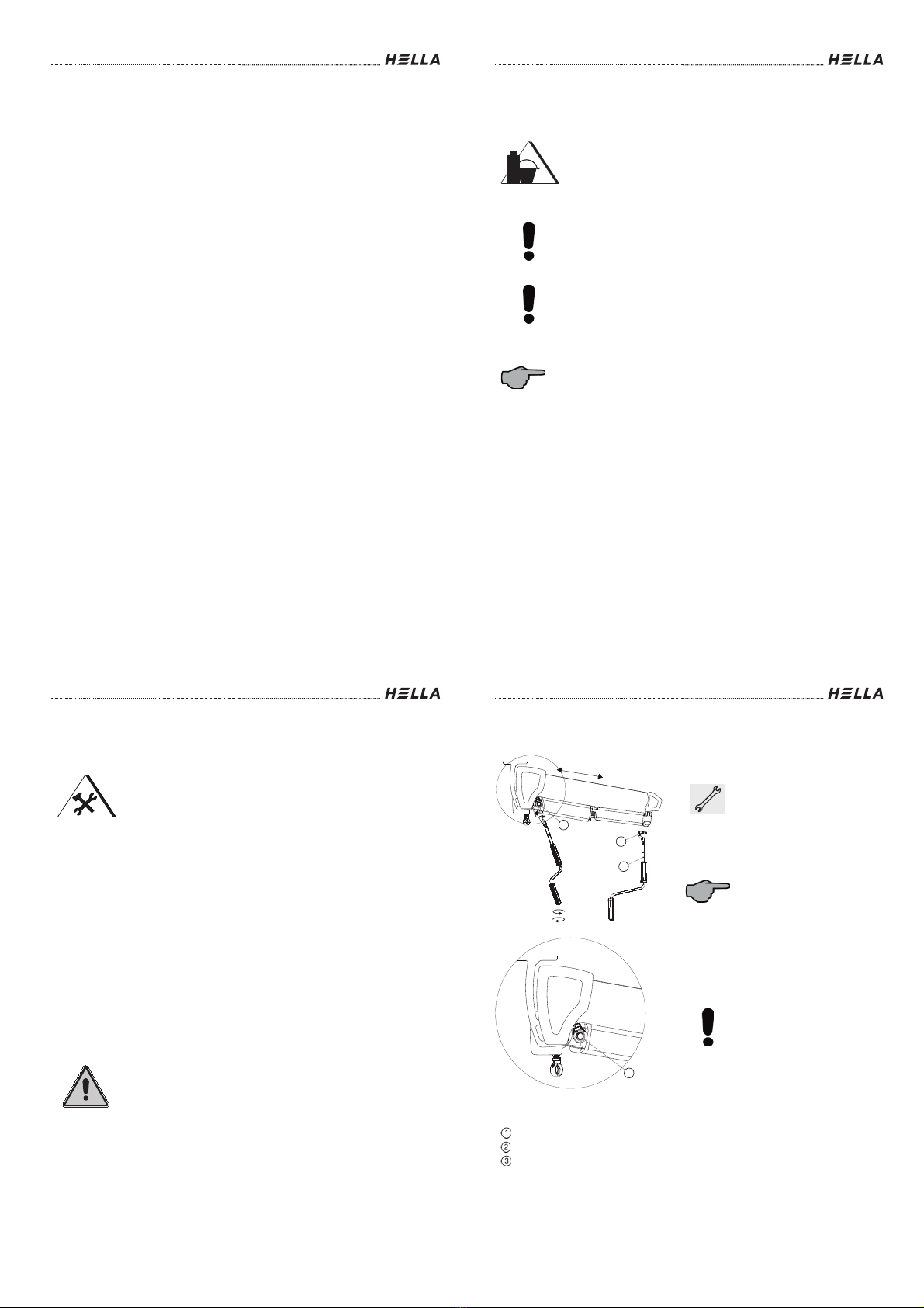
Legend
Crank handle hook
Crank rod
Eyelet
Model with crank handle
drive
Stick the crank handle hook
together with the crank rod
into the eyelet.
The awning is extended or
retracted by turning the crank
rod.
The respective direction of
rotation depends on the drive
side.
In the direction of extending
the stop position of the gear
is limited by an override.
In this position you hear a
click, when turning the crank
handle beyond this stop.
Do not use force when
turning towards the upper
stop.
1
2
3
3

Installation Instructions and Instructions for Use
Subject to technical modifications –Date of Issue April/2022
15
Operating guidelines
Motor drive
The awning can be extended
or retracted by activating a
switch, a hand
-held radio
transmitter or an automatic
device.
The end points of the drive
are adjusted ex works.
Please observe the enclosed
instructions of the
manufacturer of the drive, if
any modification is required.
Legend
Crank handle hook
Crank rod
Variomatic
Variomatic with crank
handle drive
Activate the Variomatic only,
if the awning is extended for
approx. 1 - 1.5 m.
Stick the crank handle hook
together with the crank rod
into the eyelet of the
Variomatic.
By turning the crank rod the
folding arms are
simultaneously raised or
lowered.
The inclination angle is
adjustable from approx. 0° to
40°.
Do not use force when
turning towards the upper
stop.
1
3
2
Installation Instructions and Instructions for Use
16
Subject to technical modifications –Date of Issue April/2022
Operating guidelines
Variotronic with radio or switch control
The Variotronic enables an electrically operated inclination adjustment from approx. 0° to
40°.
Legend
Variotronic
Activate the Variotronic only, if the awning is extended for approx. 1 - 1.5
m.
1
Installation Instructions and Instructions for Use
Subject to technical modifications –Date of Issue April/2022
17
Operating guidelines
Lighting
By activating a radio transmitter or an automatic device the lighting is
switched on or off or dimmed. You will find detailed information in the
enclosed instructions of the manufacturer.
Hand-held radio transmitter with scroll wheel
Setting the scroll wheel function with hand-held radio transmitter “Somfy
Situo 5 Variation A/M io”:
-Open the rear housing cover
-Set the selector switch for the operating mode “E” to position 2
In this way the scroll wheel reacts to the LED lighting and heating. You will
find detailed information in the enclosed instructions of the manufacturer.
2
E
Installation Instructions and Instructions for Use
18
Subject to technical modifications –Date of Issue April/2022
Operating guidelines
Legend
Crank handle hook
Crank rod
Eyelet
Front rail
Varioplus roller blind with crank handle
drive
Stick the crank handle hook
of the crank rod into the
eyelet of the Varioplus drive
situated at the front rail.
The blind is raised or lowered
by turning the crank handle.
The respective direction of
rotation depends on the drive
side.
Do not use force when
turning towards the upper
stop.
Varioplus Roller Blind: Motor drive with radio or switch control
- The roller blind can be raised or lowered by activating a remote control or a switch.
- The end points of the drive are set in the factory; should any modifications be
necessary, please observe the instructions in Chapter "Alignment of the awnings –
Adjusting the end positions".
4
3
1
2

Installation Instructions and Instructions for Use
Subject to technical modifications –Date of Issue April/2022
19
Before installation
Check the product immediately for possible shipping damage and for
compliance with the delivery receipt.
If parts are missing or damaged, please consult your supplier immediately.
Check the mounting base and ensure that the mounting material to be
used complies with the given conditions to guarantee proper installation. In
case of doubt, please seek advice from a specialist enterprise for fixing
techniques.
The packaging cardboard box should not be exposed to humidity. To
protect it from rain during transport, it should be covered by a foil.
Carry larger units by two persons. Transport and store the units carefully
to prevent injury of persons and
damage to the product.
Remove the packaging material carefully. When using a knife, be careful
not to damage the packaging content and to avoid cuts!
Dispose of the packaging material via recycling.
Caution!
A wrong installation can
endanger the user seriously. Please strictly
observe the installation instructions. Close off the place of installation.
When working at higher heights, there is risk of falling. Suitable ascent
supports, scaffoldings and fall protection devices are to be used. Please
make sure that the ascent supports stand solidly and provide a firm grip.
Installation Instructions and Instructions for Use
20
Subject to technical modifications –Date of Issue April/2022
Overview folding arm awning VIVA 7040
Legend
End cap
Front rail
Folding arm
Brackets
Arm bearing
Stay pipe
Supporting bearing (acc. to design)
12
3
4
5
6
7
Installation Instructions and Instructions for Use
Subject to technical modifications –Date of Issue April/2022
21
Overview tensioning bracket types
Legend
Wall bracket type A (034705V1)
Wall bracket type C (034705U5)
Wall bracket type B (03470534)
Wall bracket type I (034705V3)
Wall bracket type D (034705U7)
12
3
4
5
Installation Instructions and Instructions for Use
22
Subject to technical modifications –Date of Issue April/2022
Overview tensioning bracket types
Legend
Ceiling bracket type E (034705U2)
Ceiling bracket type H (034705U8)
Ceiling bracket type F (034705U4)
Rafter bracket type K (034705U9)
Ceiling bracket type G (034705U6)
12
34
5

Installation Instructions and Instructions for Use
Subject to technical modifications –Date of Issue April/2022
23
Installation of wall / ceiling brackets
You specified the number, form and type of brackets on purchasing the awning in
accordance with the size, the mounting base, the screw pull-out forces, the mounting
material and the wind resistance classes. Recommendations can be found in our awnings
price list and the product-related calculation tables.
Before starting the installation, please check whether the details you gave
in your order concerning the mounting base comply with the given
mounting base. In case of doubt, please obtain information from a
specialist shop or a structural engineer.
If there are any discrepancies that could jeopardise the safety, the
installation must not be carried out. The wind class given may need to be
reduced.
Mark the position of the brackets (2) correspondingly:
-Determine the position for the holes of the fastening screws
(measure, adjust, mark).
-Boretheholes.
- Install the brackets on the wall/ceiling (3) with a distance of max. 400
mm to the folding arm bearing.
Check the alignment of the brackets by means of a mason's level or a
standard. The brackets must be situated on one level both horizontally
and vertically! Irregularities in the mounting base must be equalised
accordingly.
-Observe the torque indications of the anchor manufacturer when
tightening the screws. Please note, that the bore hole geometry is
decisive for the load-bearing capacity of an anchor.
- All elongated holes defined in the bracket must be used for fastening.
-When determining the installation position, pay attention to the
supporting clamps possibly situated on the stay pipe.
Do not fix brackets in the area of the supporting clamps and arm
bearings.
The figure gives examples for the possible positions of the brackets
Installation Instructions and Instructions for Use
24
Subject to technical modifications –Date of Issue April/2022
Installation of wall / ceiling brackets
Legend
Arm bearing
If a supporting bearing is provided in
the centre, then fix the brackets
offset by approx. 150 mm.
Outer edge of the awning
(tube bearing)
Possible bracket positions
Max. 400 mm
Attention:
By default, the unit is symmetric B = C and E = F. The B- C- E- and F-dimension can be
changed for asymmetric applications (e.g. with rafters) by +/-200 mm each.
Condition 1: Arm bearing dimension B and C min. 85 mm / max. 1200 mm. (see table
standard dimensions arm bearing positions)
Condition 2: Collision check of the arms
Condition 3: Collision check between arm bearing/ cover support and LED control unit
This deviation must always be indicated in the order by means of a sketch.
- Mount the brackets with a max. distance of 400 mm to the arm bearing.
- Dimension from the outer edge of the awning up to the middle 1. Bracket max. 1100
mm.
150 150
1
2
3
4
5
333
1
2
≤ 1100 ≤ 400 ≤ 400
≤ 1100
B/C ≤ 1200
Installation Instructions and Instructions for Use
Subject to technical modifications –Date of Issue April/2022
25
Installation of wall / ceiling brackets
Check the mounting base and determine the appropriate mounting
material taking into account the mounting base and the fixing devices.
Information on the pull-out forces can be found in the documents in force.
Fix the brackets to the mounting base in accordance with the working
guidelines.
Legend
Unifilar drawing wall bracket
Unifilar drawing ceiling bracket
12
Installation Instructions and Instructions for Use
26
Subject to technical modifications –Date of Issue April/2022
Rafter bracket installation
Check the rafters (1) for their material condition or for sufficient stability.
Align the rafter holder (2) and fix it to the rafter.
Based on the holes of the rafter holder, create the relevant through holes
(3) and attach the holder. Check if the holding device fits well.
Connect the rafter holder and the ceiling bracket (4) by means of the
enclosed threaded screws and nuts and align them.
The brackets must be situated on one level both horizontally and
vertically. It may be necessary to level out irregularities on the mounting
base.
Legend
Rafter
Plain washer
Rafter holding device
Nut
Mounting holes
Fixing material
Ceiling bracket
3
1
2
4
5
67

Installation Instructions and Instructions for Use
Subject to technical modifications –Date of Issue April/2022
27
Installation on concrete
Installation of the anchor bolts as per
approval ETA-05/0069:
- Drilled hole preparation ø12 mm
Installation of the attachment:
-
Tightening torque as per ETA-
05/0069
Legend
Concrete
Installation set 1; anchor bolt FAZ II M12
Bracket
Minimum anchoring depth - 70 mm
12
3
4
Installation Instructions and Instructions for Use
28
Subject to technical modifications –Date of Issue April/2022
Installation on concrete up to 60 mm ETICS
Installation of the anchor rod as per
approval ETA-12/0258:
-Drilled hole preparation ø14 mm
- Observe the anchoring depth and
the minimum edge distance!
-Drilled hole cleaning
-Fill drilled hole with mortar FIS SB
- Slide the anchoring element into
the drilled hole
- Wait for the curing time
Installation of the attachment:
-
Cut free lock nut in the ETICS
-
Align lock nuts
(1 mm before the plaster level) and
then seal the expansion joint
- Cut the threaded rod to the correct
length
- Screw down the bracket
Legend
Concrete
Thickness of the non-bearing layer
<60 mm
Installation set 8; anchor rod M12
Anchoring depth 140 mm = drilled
hole depth
ETICS
Lock nut + washer
Bracket
123
4
5
6
7
Installation Instructions and Instructions for Use
Subject to technical modifications –Date of Issue April/2022
29
Installation on concrete 60-200 mm ETICS
Installation of the anchor rod as per
approval ETA-02/0024:
-Drilled hole preparation ø18 mm
- Observe the anchoring depth and
the minimum edge distance!
-Drilled hole cleaning
-Fill drilled hole with mortar FIS V
- Slide the anchoring element into
the drilled hole
- Wait for the curing time
Installation of the Thermax as per
approval Z
-21.8-1837:
-
Mill open the thermal insulation
prior to injection
- Sealing of the expansion joint
Installation of the attachment:
-Tightening torque as per Z-21.8-
1837
- Sealing of the free elongated hole
parts
Legend
Concrete
Bracket
Installation set 3; Thermax 16/170
M12
Thickness of the non-bearing layer
up to 200 mm
ETICS
Anchoring depth 140 mm = drilled
hole depth
Depending on the thickness of the non-bearing layer, different brackets
must be used (60-170 mm; 170-200 mm).
1
23
4
5
6
Installation Instructions and Instructions for Use
30
Subject to technical modifications –Date of Issue April/2022
Installation on brickwork
Installation of the anchor rod as per
approval ETA-10/0383:
Depending on the type of stone, the
injection anchor sleeve must be used!
-Drilled hole preparation
ø12 mm without sleeve
ø16 mm with sleeve (16x130)
-Drilled hole cleaning
- Fill drilled hole (anchor sleeve) with
mortar FIS V
- Slide the anchoring element into
the drilled hole
- Wait for the curing time
Installation of the attachment:
-
Tightening torque as per ETA-
10/0383
Legend
Brickwork
Installation set 2; anchor rod M10
Bracket
Anchoring depth 130 mm
drilled hole depth
1
2
3
4

Installation Instructions and Instructions for Use
Subject to technical modifications –Date of Issue April/2022
31
Installation on brickwork 60-170 mm ETICS
Installation of the anchor rod as per
approval ETA-10/0383:
Depending on the type of stone, the
injection anchor sleeve must be used!
-Drilled hole preparation
ø18 mm without sleeve
ø20 mm with sleeve (20x200)
-Drilled hole cleaning
-Fill drilled hole (anchor sleeve) with
mortar FIS V
- Slide the anchoring element into
the drilled hole
- Wait for the curing time
Installation of the Thermax as per
approval Z
-21.8-1837:
-
Mill open the thermal insulation
prior to injection
- Sealing of the expansion joint
Installation of the attachment:
-
Tightening torque as per Z-21.8-
1837
- Sealing of the free elongated hole
parts
Legend
Brickwork
Bracket
Installation set 3; Thermax 16/170
M12
Thickness of the non-bearing layer
up to 170 mm
ETICS
Anchoring depth 200 mm = drilled
hole depth
1
23
4
5
6
Installation Instructions and Instructions for Use
32
Subject to technical modifications –Date of Issue April/2022
Installation on wood
Installation of the attachment:
-Drilled hole preparation ø9 mm
- Secure bracket with wood screw
and washer
Legend
Wood
Installation set 5; wood screw ø12x120
Bracket
Drilled hole depth 125 mm
No wind protection class can be given with installation on wood due to the
variance of the building material.
12
3
4
Installation Instructions and Instructions for Use
Subject to technical modifications –Date of Issue April/2022
33
Installation on wood 60-170 mm ETICS
Installation of the anchor rods:
-Drilled hole preparation ø14 mm
- Observe the anchoring depth and
the minimum edge distance of 100
mm!
-Drilled hole cleaning
-Lubricate threaded rod
- Screw threaded rod into the wood
Installation of the Thermax following
approval Z-21.8-1837:
- Milling open the thermal insulation
- Sealing of the expansion joint
Installation of the attachment:
- Sealing of the free elongated hole
parts
Legend
Wood
Bracket
Installation set 3; Thermax 16/170
M12
Thickness of the non-bearing layer
up to 170 mm
ETICS
Anchoring depth 140 mm = drilled
hole depth
Required wood quality is C24, P30, GL24, F40/30 or equivalent with a
wood moisture of ≤15%.
23
4
5
6
1
Installation Instructions and Instructions for Use
34
Subject to technical modifications –Date of Issue April/2022
Installation on concrete ceiling face, installation set
7
Register constructional situation:
-Thickness of the concrete ceiling
-Determination of the theoretical
position of the concrete ceiling
(consider differences is in the
ground)
-Determination of the non-bearing
layer ETICS (adhesive, insulation,
plaster)
Legend
Brickwork
Concrete ceiling
ETICS
Ceiling position
Thickness of the non-bearing layer
Exclude the shape of the wooden
spacer under consideration of the
edge distances
The wooden spacers should rigidly be
seated in the insulation.
Using a "multi
-cutter" tool is
recommended for cutting out the
insulation.
The two lower drilled holes of the bracket should be preferred for
installation. The third drilled hole serves for refitting potential errors (e.g.
wrong assessment of the constructional situation or position of the
concrete ceiling).
≥ 180
1
2
3
4
5
4

Installation Instructions and Instructions for Use
Subject to technical modifications –Date of Issue April/2022
35
Installation on concrete ceiling face, installation set
7
Installation of the anchor rod as per
approval ETA-12/0258:
-Drilled hole preparation
- Observe the anchoring depth and
the minimum edge distance!
-Drilled hole cleaning
-Fill drilled hole with mortar
- Slide the anchoring element into
the drilled hole
- Wait for the curing time
Legend
Anchor rod FIS A
Insert wooden spacers and
completely seal the last wooden
spacer towards the ETICS outer
surface.
(Fischer multi-adhesive and sealant)
The 5 mm spacers must not be used
as the last spacer. Then the anchor
rods can be cut to length.
Legend
Wood distances
Last wooden spacer
Sealing joint all around
The last wooden spacer must always protrude 2-5 mm from the WDSV. A
5 mm thick wooden spacer per installation set is included as a reserve.
min. 140
min. 55
min. 55
1
1
2
3
Installation Instructions and Instructions for Use
36
Subject to technical modifications –Date of Issue April/2022
Installation on concrete ceiling face, installation set
7
Affix the bitumen band on the back
of the wall bracket type I:
Affix in a way that an even edge is
created all around.
Legend
Wall bracket type I
Bitumen band
Fixing of the bracket:
Attach the wall bracket type I; while
doing so, push the anchor rod through
the bitumen band. Position washer
and nut and tighten them. The bracket
must be sealed all around again by
means of a joint between ETICS
surface and bracket (Fischer multi
-
adhesive and sealant).
Legend
Wall bracket type I
Bitumen band
Sealing joint all around
The sealing joints are maintenance joints that must be checked and
maintained at regular intervals in order to prevent consequential damage.
1
2
1
3
Installation Instructions and Instructions for Use
Subject to technical modifications –Date of Issue April/2022
37
Further installation situations, installation set 7
Constructional situation pressure-resistant
installation on concrete
With this application, the wall bracket type I must be
ordered and installed in combination with the mounting
set 2.
Constructional situation with
ceiling edge insulation and ETICS
The wooden spacers must be properly
cut to length on site.
The constructional situation must be
determined before placing the order.
The dimension of the load-bearing
layer must be indicated and is only
available for the thicknesses indicated
in the price list.
Legend
Thickness of the non-bearing layer
1
Installation Instructions and Instructions for Use
38
Subject to technical modifications –Date of Issue April/2022
Further installation situations, installation set 7
Constructional situation with ceiling insulation and
plaster
At least 50 mm non-bearing layer (see price list).
Legend
Thickness of the non-bearing layer
1
Installation Instructions and Instructions for Use
Subject to technical modifications –Date of Issue April/2022
39
Installation of the awning
The articulated arms are under high mechanical stress. The cover
prevents a discharge of this potential energy. With linked awnings the
articulated arms are ex works protected with an arm fixing device.
Before taking the linked awning out of the packaging, please check these
safety tapes for correct fit and damage.
There is danger to life and risk of injury.
As shown below, push the awning with the stay pipe into the brackets and
fix it immediately with the bracket joint bar and the safety screws. After
that, tighten the two clamping screws.
Legend
Stay pipe
Bracket
Bracket joint bar
Safety screw
Locking screw
Attention!
It is not allowed to extend
the awning before the
safety screw is fixed. There
is a high risk of injury and
danger to life!
1
2
3
4
5
3
Installation Instructions and Instructions for Use
40
Subject to technical modifications –Date of Issue April/2022
Installation of the awning
Observe the installation dimensions as shown below.
Wall installation
Ceiling installation
Rafter installation
246
244
(64)
282
273
(64)
282
273
(64)
Installation Instructions and Instructions for Use
Subject to technical modifications –Date of Issue April/2022
41
Adjusting the awning
Legend
Adjusting unit
Allen key
Covering
Inclination adjustment with Variomatik
arm bearing
The VIVA folding arm awnings are supplied
with an arm bearing to allow for inclination
adjustment.
Ex works, the inclination angle is approx.
15° and it can be later adjusted from
approx. 0° to 40° by means of an adjusting
spindle.
The horizontal position of the front rail is
adjusted ex works.
If a modification is required, please proceed
as described in the following:
Extend the awning for
approx. 1
- 1.5 m.
Remove the covering from
the opening of the adjusting
unit.
Insert the enclosed Allen key
into the opening of the
adjusting unit.
The folding arm raises or
lowers by turning the Allen
key.
The respective arm can be
adjusted easier, if a second
person holds up the front rail.
Proceed analogously with the
second adjusting mechanism.
Please check the correct
adjustment with a level.
1
2
3
Installation Instructions and Instructions for Use
42
Subject to technical modifications –Date of Issue April/2022
Adjusting the awning
Legend
Allen head screw
Inclination adjustment with tilting arm
bearing
Extend the awning up to the
stop position.
Relieve the front profile by
holding up by a second
person.
Loose the Allen head screw
of only one folding arm.
Raise or lower the front
profile until the desired
inclination is attained.
Tighten the Allen head screw.
Proceed analogously with the
second adjusting mechanism.
Adjusting the roller tube
If the awning does not close
correctly or if the cover does
not roll up symmetrically, you
can adjust the roller tube as
follows:
Remove the end caps on
both sides by loosening the
countersunk drilling screw.
Legend
Countersunk drilling screw
End cap
1
1
2

Installation Instructions and Instructions for Use
Subject to technical modifications –Date of Issue April/2022
43
Adjusting the awning
Horizontal adjustment of the front rail
and inclination adjustment with design
variant Variomatic
Extend the awning for
approx. 1
- 1.5 m.
Open the bayonet catch and
pull out half of the primary
shaft.
When turning the eyelet, the folding arm
raises or lowers.
To adjust the folding arm opposite proceed
as follows:
Remove the primary shaft with the eyelet
from the adjusting unit 1.
Remove the covering from the opening of
the adjusting unit 2 and take out the Allen
head screw laying inside.
Insert the primary shaft into the opening of
the adjusting unit 2.
When turning the eyelet, the folding arm
raises or lowers.
The respective arm can be
adjusted easier, if a second
person holds up the front rail.
Pull-out the primary shaft and fix it again to
the adjusting unit 1.
Close the opening of the adjusting unit 2
with a plug.
Please check the correct adjustment with a
level.
Legend
Adjusting unit 1
Bayonet catch
Adjusting unit 2
Eyelet
Primary shaft
Covering
1
1
2
3
4
5
2
6
Installation Instructions and Instructions for Use
44
Subject to technical modifications –Date of Issue April/2022
Adjusting the awning
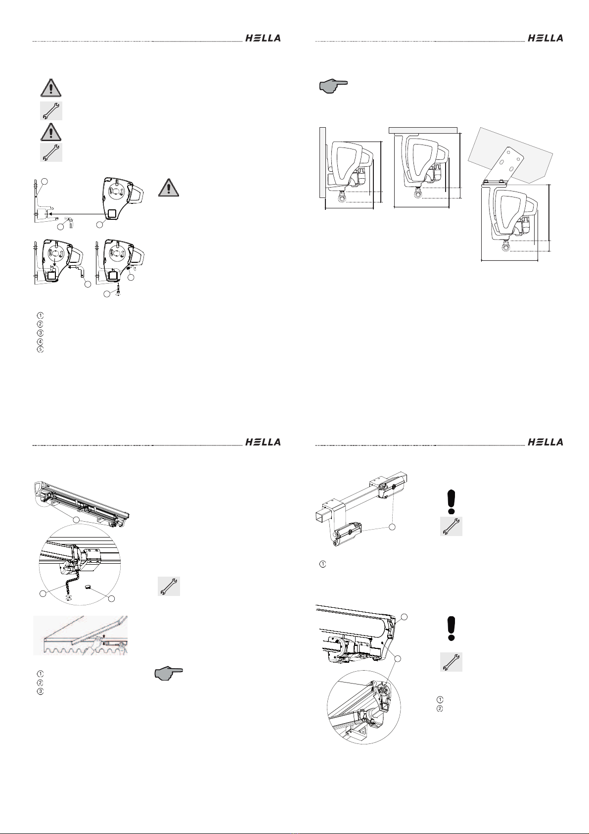
Arm adjustment
Ex works your awning is optimally adjusted. To ensure a correct closing of the awning, the
folding arms (1) should be in a parallel position to the front rail (2). The arm bearing bolt is
mounted in an eccentric bush (6). You can adjust the folding arms at any time as follows:
In order to correct the angle, you must open the fastening screw for the
eccentric bush (4) by means of an Allen key 2.5 mm (5) first. In order to
access the threaded pin, you must extend the awning (see illustration on
the next page).
Then retract the awning to approx. 0.5 m and correct the position of the
arm by turning the eccentric bush (6) by means of an Allen key 8 mm (7).
Please note: The position mark (9) of the eccentric bush must be within
the indicated adjustment range (10). Otherwise the parallelism of the arm
to the casing can be adjusted, however, the awning will still extend askew.
The arm should be parallel to the casing of the awning! For facilitated
adjustment, the arm can be supported by hand (8).
Check the adjustment of the inclination and, if necessary, repeat the
described procedure until the desired result has been reached.
Now the adjusting procedure of the arm bearing (3) regarding the arms is
finished. The adjusting procedure on the right side must be performed
analogously.
Please note: Finally re-tighten the fastening screws (4)!
Installation Instructions and Instructions for Use
Subject to technical modifications –Date of Issue April/2022
45
Adjusting the awning
Arm adjustment
Legend
Folding arm
Lifting the folding arm
Front rail
Position mark of the eccentric bush
Arm bearing
Adjustment range (opposite side in
mirror image)
Clamping screw for eccentric bush
Rear stay pipe
Allen key AF2.5
Bottom stay pipe
Eccentric bush for arm adjustment
Wall / rear side
Allen key A/F 8
8
2
1
5
7
4
6
3
9
10
min.
max.
6
4
3
min.
10
11 12
13
Installation Instructions and Instructions for Use
46
Subject to technical modifications –Date of Issue April/2022
Adjusting the awning
Adjusting the supporting profiles
Depending on the type, the VIVA awnings are provided with differently adjustable
supporting profiles.
Legend
Available supporting profiles
Legend
Fabric support
Adjusting screw
1. Cover support for VIVA from a width
of 4501 mm.
Raising or lowering the cover
support by turning the
adjusting screw.
1
1
2

Installation Instructions and Instructions for Use
Subject to technical modifications –Date of Issue April/2022
47
Adjusting the awning
Legend
Upper covering profile
Adjusting screw
2. Support of the upper covering profile
for VIVA plus, from a width of 4501 mm.
Raising or lowering the upper
covering profile by turning the
adjusting screw.
1
2
Installation Instructions and Instructions for Use
48
Subject to technical modifications –Date of Issue April/2022
Adjusting the awning
3. Cover support and support for the
upper covering profile for VIVA plus
from a width of 4501 mm.
Raising or lowering the cover
support by turning the
adjusting screw.
Raising or lowering the upper
covering profile by turning the
adjusting screw.
Legend
Adjusting screw
Fabric support
Fabric tray
Upper covering profile
4. Fabric tray holding device for VIVA
super from a width of 4501 mm.
Raising or lowering the cover
tray by turning the adjusting
screws.
4
1
1
2
1
3
Installation Instructions and Instructions for Use
Subject to technical modifications –Date of Issue April/2022
49
Adjusting the awning
Adjusting the end positions
Legend
Fixing screw
Change gear end points with awning
with crank handle operation:
The end points of the crank
handle gear can be adjusted.
If the adjustment ex works is
to be changed, please
proceed as follows:
Extend the awning until the
stop position is reached (you
hear a click).
Release the fixing screw (1).
Move the awning with the
crank rod to the desired
position.
Tighten the fixing screw (1).
1
Installation Instructions and Instructions for Use
50
Subject to technical modifications –Date of Issue April/2022
Adjusting the awning
Adjusting the end positions
Varioplus roller blind with motor drive and remote control
The roller blind can be raised or lowered by activating a hand-held radio transmitter. The
end points of the drive are adjusted ex works, however, can be changed by means of a
handheld radio transmitter.
Please observe the enclosed instructions of the manufacturer of the motor, if any
modification is required.
Varioplus roller blind with motor drive and switch controls or ONYX
The roller blind can be raised or lowered by activating a mechanical switch or the ONYX
control. The end points of the drive are adjusted ex works, however, must be mechanically
adjusted by turning the 2 adjustment screws (4) on the motor head (3) in case of changes.
These adjustment screws are hidden underneath the end cap (1) and can be accessed via
its drilled holes (5) by means of an Allen key 4 mm (6). However, the plastic covering caps
(7) must be removed first.
Detailed instructions for adjusting the end positions can be found in the enclosed
documents of the motor manufacturer.
Legend
End cap
Front rail
Motor head
Adjustment
screws for end
positions
Adjustment holes
Allen key 4 mm
Plastic covering
caps
2
1
2
3
5
1
4
6
7
2
Installation Instructions and Instructions for Use
Subject to technical modifications –Date of Issue April/2022
51
Design Option: Protection against bad Weather
Push the wall connection
profile against the mounting
base.
Due to the special shape of
the profile, a sealing with
appropriate sealing materials
towards the mounting base is
possible.
In case of doubt, please
consult your specialist shop
for joint techniques.
Legend
Wall connection profile
1
1
Installation Instructions and Instructions for Use
52
Subject to technical modifications –Date of Issue April/2022
Installation linked units
Standard situation
Attention:
The awning elements are under high mechanical stress. Exercise
highest caution when hooking-in or opening the elements!!
The linked VIVA awning is supplied with a continuous cover. Cover with
clamping seal, cover seal, valance and valance seal are enclosed loosely.
It is not possible to fix a bracket in the area of the arm bearing and the
supporting bearing. The possible positions of the brackets are shown in
the example drawing.
Legend
Width of the unit
Max. 400 mm
Bracket
Arm bearing positions
Support bearing below a seam
Fix the brackets for the driven and the linked element. Observe the
specifications of the enclosed drawing as well as the descriptions and
information for single awnings in the Chapters "Wall/ceiling bracket
installation" or "Rafter bracket installation" in these instructions.
Respect the additional lateral space requirement of approx. 500 mm with
installation in a recess.
Remove the linked as well as the driven awning from the packaging.
The folding arms of the awning are protected with sufficiently
dimensioned tapes; do not remov
e these tapes, there is highest
danger of accident!
2
1/4 1/4 1/4 1/4
1
23
4
5
222
3
5
4
4
4
4
4
4
4
55
Installation Instructions and Instructions for Use
Subject to technical modifications –Date of Issue April/2022
53
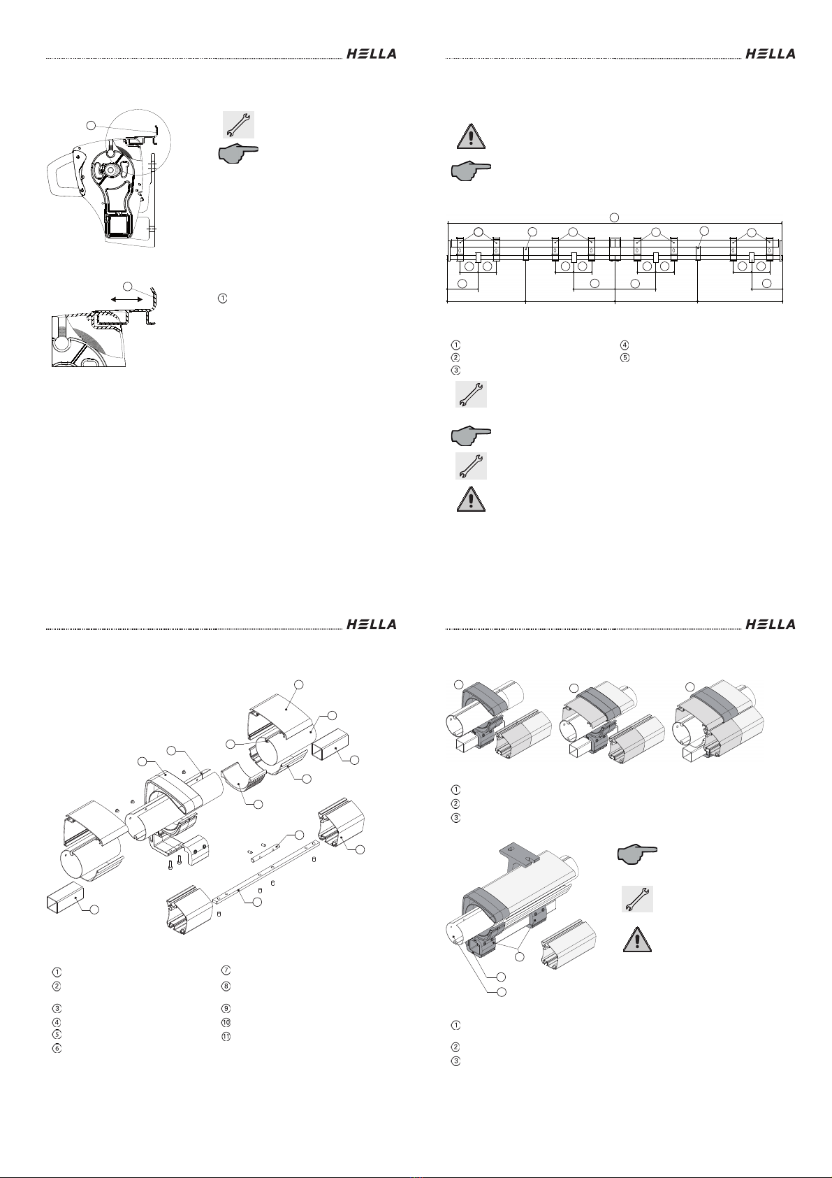
Overview Linking Elements
Fig. 1
Legend
Coupling bracket
Fabric tray
Roller tube coupling
Supporting surface for the roller
tube*
Groove of the roller tube
Front rail
Roof profile
Connecting pin
Roller tube
Connecting strip
Stay pipe
* ... The supporting surface for the roller tube is available in two designs:
- VIVA / VIVA plus
- VIVA super
1
2
3
4
5
6
7
8
9
10
11
6
Installation Instructions and Instructions for Use
54
Subject to technical modifications –Date of Issue April/2022
Overview Linking Elements
Legend
VIVA 7040
VIVA plus 7040
VIVA super 7040
Legend
Bracket joint bars and
safety screws
Coupling bracket
Coupling of the cover roll shaft
Ex works the coupling
bracket and the coupling of
the roller tube are pre
-
installed to the driven awning.
Push the driven awning into
the brackets as described in
the chapter "Installation of
the awning".
Secure the awning
immediately with the bracket
joint bars and safety screws,
without turning these screws
too tight. The awning must
remain movable during the
installation so that it can be
coupled with its 2nd half.
123
1
2
3

Installation Instructions and Instructions for Use
Subject to technical modifications –Date of Issue April/2022
55
Overview Linking Elements
Legend
Connecting strip
Connecting pin
Insert the connecting strip
and the connecting pin into
the front rail.
Legend
Roller tube coupling
Roller tube
Push the coupled awning into
the brackets as described in
the chapter "Installation of
the awning".
Again, secure this awning
immediately with the bracket
joint bars and safety screws,
without turning these screws
too tight. The awning must
remain movable during the
installation so that it can be
coupled with its 2nd half.
Respect the necessary
distance of approx. 500 mm
between the two awnings.
1
2
1
2
Installation Instructions and Instructions for Use
56
Subject to technical modifications –Date of Issue April/2022
Overview Linking Elements
Legend
End cap
End cap screw
Upper covering profile
Screws for upper covering profile
Profile of the lower covering (only
with VIVA super)
Dismantle the end cap (1) on
both awning halves by
loosening the screws (2).
Remove the upper covering
profile (3) on both awning
halves by unscrewing the
screws (4).
(only with Viva plus and Viva
super).
1
2
3
4
5
Installation Instructions and Instructions for Use
Subject to technical modifications –Date of Issue April/2022
57
Overview Linking Elements
Legend
Linked element
Driven element
Roller tube coupling
Roller tube (drive)
Roller tube (coupled)
Countersunk blind rivet
Connecting pin
Connecting strip
Coupling bracket
Push together both awnings,
inserting the coupling of the
roller tube into the roller tube
at the same time.
Please note, that the grooves
of the roller tube are in one
row.
Connect the coupling of the
roller tube to the roller tube
with the countersunk blind
rivets supplied.
1
9
2
3
4
6
7
8
5
Installation Instructions and Instructions for Use
58
Subject to technical modifications –Date of Issue April/2022
Overview Linking Elements
Center the connecting strip
(8) and the connecting pin (7)
above the butt joint of the two
stay pipes and fix them.
After riveting the roller tube,
fix the coupling bracket (9) on
the stay pipe (10) by means
of clamping screws (11).
Then tighten the two (4)
threaded pins. Screw the
coupling bracket (9) to the
cover trays (12) and the
supporting surface for the
roller tube. For this purpose
use the pan head tapping
screws (13) enclosed in the
delivery.
Legend
Connecting pin
Connecting strip
Coupling bracket
Stay pipe
Clamping screws
Fabric tray
Pan head tapping screw 4.2x13
Threaded pin M10x16
~50
~50
~100
~100
8
7
9
10
11
13
12
14

Installation Instructions and Instructions for Use
Subject to technical modifications –Date of Issue April/2022
59
Overview Linking Elements
VIVA 7040
VIVA super 7040
VIVA plus 7040
Legend
Blind rivet
Groove of the roller tube
Supporting surface for the roller
tube
Pan head tapping screw 4.2x13
2
3
4
1
1
2
3
4
1
2
3
4
Installation Instructions and Instructions for Use
60
Subject to technical modifications –Date of Issue April/2022
Overview Linking Elements
Loose the arm tapes (4)
slightly and extend the folding
arms (3) a bit to provide a
support for the covers.
Attention! Be very careful,
there is risk of injury or
danger to life.
Legend
Front rail
Stay pipe
Folding arm
Arm tape (safety tapes)
Place the roll with the awning
cover on the folding arms.
Insert the lower seal seam
into the groove of the front
rail and push
-in the seal
laterally (1x left, 1x right) up
to the middle of the cover
with the help of the seal tips.
If the seal cannot be pushed
in, a cordless drill can be
used should it be necessary.
Clamp the seal into the drill
and slowly screw it in.
Legend
Keder seam
Folding arms
Keder
Cover
1
2
3
4
3
4
2
1
Installation Instructions and Instructions for Use
Subject to technical modifications –Date of Issue April/2022
61
Overview Linking Elements
Legend
Groove insertion
As an alternative remove the
front rail and push over the
cover kedered before.
Legend
Clip seal
Round groove
Roller tube
Push the clip seal that is fixed
to the upper end of the cover
into the round groove of the
roller tube.
Roll up the cover with motor
power onto the cover roll
shaft.
Roll up the cover only so
far, that the folding arms
do not put pressure on the
cover. There is risk of
injury or danger to life due
to a possible tripping of the
roller tube.
1
1
2
3
Installation Instructions and Instructions for Use
62
Subject to technical modifications –Date of Issue April/2022
Overview Linking Elements
Legend
Cover support
Holding device for the cover tray
Legend
Holding device for the cover tray
Check the position of the pre-
installed holding device of the
cover tray with VIVA super.
These must always be
placed below a strip seam!
Move them in the cover tray if
required.
12
1

Installation Instructions and Instructions for Use
Subject to technical modifications –Date of Issue April/2022
63
Overview Linking Elements
Check the positions of the
cover supports with VIVA and
Viva plus.
These must always be
placed below a strip seam!
Move them in the cover tray if
required.
Legend
Fabric support
Legend
Coupling bracket
Stay pipe
Fixing screws
Insert the upper covering
profile of the linked awning,
and fix it through the bore
holes of the roller tube
bearing, as described before.
Check the solid position of the coupling
bracket on the stay pipe; tighten up the
screws if necessary.
Remove the arm fixations carefully.
Test running of the unit, adjusting of the
cover and fixing with seal clamps.
An adjusting of the cover
over the roller tube or an
adjusting of the supporting
profiles, as described in the
section "Adjusting of the
awning", can become
necessary.
Tighten up all screwed
connections.
1
1
2
3
Installation Instructions and Instructions for Use
64
Subject to technical modifications –Date of Issue April/2022
Installation of linked awnings:
Special Situation
Legend
Bore of the bearing
Shaft bearing
Roof profile
Lower covering profile
Stay pipe
Threaded pin
Situation 1:
The driven awning is
installed. The arrangement of
the mounting brackets does
not allow for a lateral moving
of the linked unit in the
mounting brackets.
Procedure:
Remove the end caps, the
profile of the upper covering
and the profile of the lower
covering from the linked unit
as described above.
In addition, the tube bearing
and the roller tube have to be
removed. To do this, loosen
the threaded pin and push
the tube bearing from the
stay pipe.
123
4
5
6
Installation Instructions and Instructions for Use
Subject to technical modifications –Date of Issue April/2022
65
Installation of linked awnings:
Special Situation
Hook in the awning into the mounting brackets, as described above.
Afterwards push the roller tube on the roller tube coupling and provide the
coupling connection as described above. Hook in again the profile of the
upper covering and the profile of the lower covering. Push the tube
bearing onto the stay pipe, positioning the roller tube in the bearing bore.
Fasten the tube bearing with the threaded pin, and screw together laterally
the profile of the upper covering and the profile of the lower covering
through the tube bearing.
The subsequent installation is carried out analogously to the standard
situation.
Situation 2:
The awning is installed in a recess, the required lateral space is not
available.
Approach:
Place the awning on a suitable support and provide the coupling
connections as described above. With the help of several persons (at least
4) hook in the complete unit into the mounting brackets and protect it
immediately with bracket joint bars and safety screws.
The subsequent installation is carried out analogously to the standard
situation.
Installation Instructions and Instructions for Use
66
Subject to technical modifications –Date of Issue April/2022
Electric commissioning and overview table power
This general overview table shows which awning designs are possible with an electric
control.
Possible types of operation
Somfy
cord-bound
Somfy radio
io
ONYX
Cord
operated
Awning drive
yes
yes
yes
no
Varioplus roller blind
yes
yes
yes
no
Drive system Variotronic
yes
yes
yes
no
LED lighting
no
yes
yes
no
Heater
yes
no
no
yes
Installation Instructions and Instructions for Use
Subject to technical modifications –Date of Issue April/2022
67
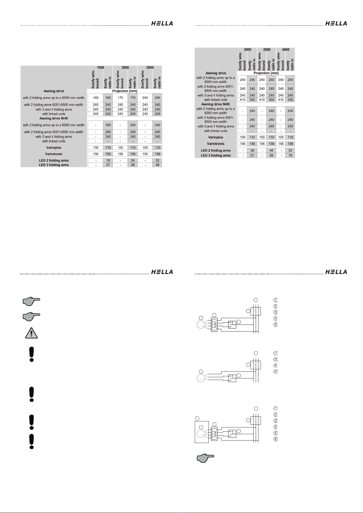
Electric commissioning and overview table power
Technical data of the awning
Connection for all cables: 220-240V / 50-60Hz
Overview powers [W]
Installation Instructions and Instructions for Use
68
Subject to technical modifications –Date of Issue April/2022
Electric commissioning and overview table power
Installation Instructions and Instructions for Use
Subject to technical modifications –Date of Issue April/2022
69
Activation guidelines for electric drives
The motors we use are drives with integrated planetary gear, brakes, limit
stops at the top and at the bottom, and thermo cut-off switches, also not
only a motor, but a complete drive system.
In some respect, the drives do NOT correspond to other household
electrical consumers. Please strictly observe the following notes and
safety instructions.
The construction, checking, commissioning and error-correcting of the
electrical system are only allowed to be carried out by an electrician (acc.
to VDE 0100). In case of improper connection, considerable danger can
arise for the user.
-Follow the wiring diagram precisely!
-We cannot accept responsibility for damage, that can result from
improper installation.
-Never simultaneously activate the drives with an UPWARDS and a
DOWNWARDS signal!
-Keep a break of approx. 0.5 seconds between the UPWARDS and
the DOWNWARDS command (is often neglected with Instabus EIB-
systems).
Radio interference suppression
The drives are provided with a radio interference suppression according to
the current VDE standards and EC Guidelines. If the drives are operated
with other devices, that include interferences, it is the fitter's duty -as part
of the obligation to suppress interference -to ensure that the entire unit
complies with the current regulations.
Operation in wet spaces
The drives are "splash-proof"; if they are operated in wet spaces, the VDE-
guidelines, inter alia VDE 0100/Parts 701, 702, the guidelines of the local
electric supply companies and of the TÜV must be observed and fulfilled.
Both the instructions and notes given in these instructions, as well
as the instructions and notes given in the respective enclosed
instructions of the manufacturers of the drive systems must be
observed.
Installation Instructions and Instructions for Use
70
Subject to technical modifications –Date of Issue April/2022
Wiring diagram for motors with switch operation
Drive system awning
Legend
Drive system awning
Hirschmann connector
Junction box
Switch
Mains
Drive system Varioplus
No PE available!
Legend
Drive system Varioplus
Junction box
Switch
Mains
Drive system Variotronic
Legend
Drive system Varotronic
Hirschmann connector
Junction box
Switch
Mains
Variotronic box
For more details concerning the electrical connections, powers, operating
instructions and programming, please refer to the enclosed documents of
the manufacturer or the HELLA installation instructions.
It is essential that switches for the awning drive be electrically and
mechanically locked.
M
1
3
1 N
2
3
PE
2
4
1
5
L1 NPE
M
1
3
4
5
1
L1 NPE
M
1
3
1 N
2
3
PE
2
4
6
5
1
L1 NPE
Installation Instructions and Instructions for Use
Subject to technical modifications –Date of Issue April/2022
71
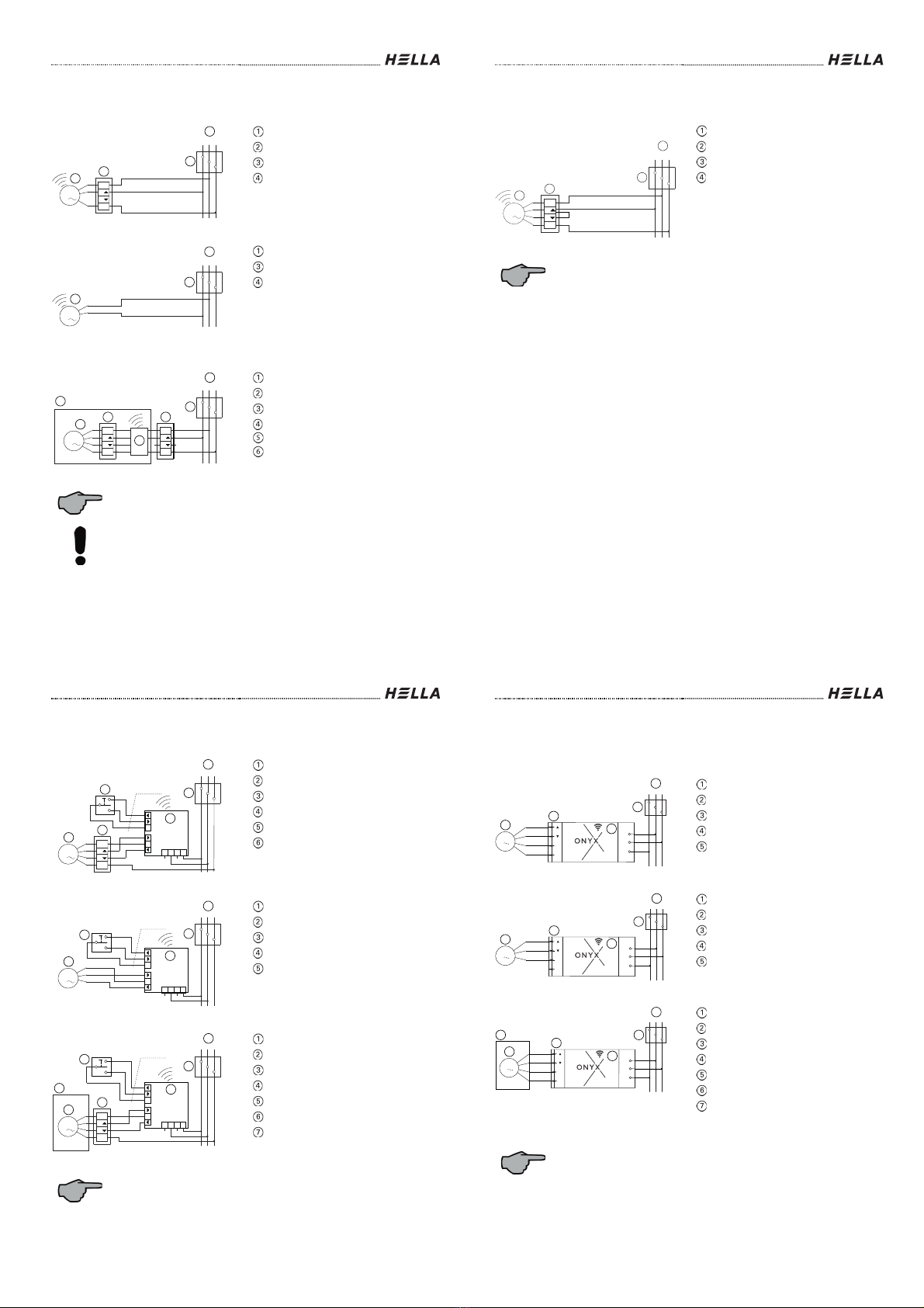
Wiring diagram for motors with Somfy io
Drive system awning
Legend
Radio drive awning
Hirschmann connector
Junction box
Mains
Drive system Varioplus
No PE available!
Legend
Radio drive Varioplus
Junction box
Mains
Drive system Variotronic
Legend
Radio drive Varotronic
Hirschmann connector
Junction box
Mains
Slim Receiver RTS
Variotronic box
For more details concerning the electrical connections, powers, operating
instructions and programming, please refer to the enclosed documents of
the manufacturer or the HELLA installation instructions.
With the radio system Somfy io all receivers must be taught one after
another (order does not matter), i.e. do not connect several receivers to
the network at the same time as the radio system does not support a
simultaneous teaching process of multiple components.
3
1 N
2
3
PE
2
M
1
4
1
L1 NPE
M
1
3
4
1
L1 NPE
M
1
3
1 N
2
3
PE
2
6
1 N
2
3
PE
2
5
4
L1 NPE
1
Installation Instructions and Instructions for Use
72
Subject to technical modifications –Date of Issue April/2022
Wiring diagram for motors with elero radio
Drive system awning
Radio drive awning
Hirschmann connector
Junction box
Mains
For more details concerning the electrical connections, powers, operating
instructions and programming, please refer to the enclosed documents of
the manufacturer or the HELLA installation instructions.
3
1N
2
3
PE
2
M
1
4
1
L1 N PE
Installation Instructions and Instructions for Use
Subject to technical modifications –Date of Issue April/2022
73
Wiring diagram for motors with ONYX.NODE
Drive system awning
Legend
Drive system awning
Hirschmann connector
Junction box
Mains
Button
ONYX.NODE
Drive system Varioplus
Legend
Drive system Varioplus
Junction box
Mains
Button
ONYX.NODE
Drive system Variotronic
Legend
Radio drive Varotronic
Hirschmann connector
Junction box
Mains
Button
ONYX.NODE
Variotronic box
For more details concerning the electrical connections, operating
instructions and programming, please refer to the enclosed
documents
"ONYX".
It is essential that switches for the awning drive be electrically and
mechanically locked.
M
1
L1 N PE
3
1 N
2
3
PE
2
5
Local Motor
N
NNLL
Power
6
+
Typ YR 3x0,8
0,5
4
1
M
1
L1 N PE
2
4
Local Motor
N
NNLL
Power
5
+
Typ YR 3x0,8
0,5
3
1
M
1
L1 N PE
3
1 N
2
3
PE
2
Local Motor
N
NNLL
Power
+
7
5
Typ YR 3x0,8
0,5
4
6
1
Installation Instructions and Instructions for Use
74
Subject to technical modifications –Date of Issue April/2022
Wiring diagram for motors with
ONYX.CONNECTOR
Drive system awning
Legend
Drive system awning
Hirschmann connector
Junction box
Mains
ONYX.CONNECTOR
Drive system Varioplus
Legend
Drive system Varioplus
Hirschmann connector
Junction box
Mains
ONYX.CONNECTOR
Drive system Variotronic
Legend
Radio drive Varotronic
Hirschmann connector
Junction box
Mains
Button
ONYX.CONNECTOR
Variotronic box
For more details concerning the electrical connections, operating
instructions and programming,
please refer to the enclosed documents
"ONYX".
It is essential that switches for the awning drive be electrically and
mechanically locked.
N
PE
L
PE
N
1
2
3
44
1
3
2
LNPE
M
1
1
2
3
4
5
N
PE
L
PE
N
1
2
3
44
1
3
2
LNPE
M
1
1
2
3
4
5
N
PE
L
PE
N
1
2
3
44
1
3
2
LNPE
M
1
1
2
3
4
5
6

Installation Instructions and Instructions for Use
Subject to technical modifications –Date of Issue April/2022
75
Wiring diagram for motors with
ONYX.CONNECTOR
Legend
Junction box
Motor
Adapter plug ONYX.CONNECTOR
Lighting
Hirschmann plug connection
For more details concerning the electrical connections, operating
instructions and programming, please refer to the enclosed documents
"ONYX".
ONYX.CONNECTOR
22
33
11
44
Hirschmann
STAS 3
PE
N
Hirschmann
STAK 3
M
~
1,5mm²
ONYX.CONNECTOR
22
33
11
44
Hirschmann
STAS 3
PE
N
Hirschmann
STAK 3
N
L
PE
1,5mm²
1,5mm²
1
2
2
3
3
4
5
44
11
33
22
PE
N
L
Hirschmann
STAK 3
Hirschmann
STAS 3
3
N
L
PE
1,5mm²
1
44
11
33
22
PE
N
L
Hirschmann
STAK 3
Hirschmann
STAS 3
3
Installation Instructions and Instructions for Use
76
Subject to technical modifications –Date of Issue April/2022
Overview LED lighting with remote control
Legend
LED control unit*
Connecting cable 230V
Integrated LED lighting
Technical data
Light temperature
2700 K (warm-white)
Colour rendering index of the LED strips
>90
Control LED
Somfy io, ONYX (dimmable)
Operating temperature (outside temperature)
-20°C to +45°C
IP rating
IP44
Cable
10 m with open end piece
* … The control of LED lighting is possible with Somfy io or ONYX The individual modules
are described in the following.
2
3
1
Installation Instructions and Instructions for Use
Subject to technical modifications –Date of Issue April/2022
77
Replacing a folding arm with integrated LED
lighting
Schematic wiring diagram
3
77
4
99
88
8
8
8
56
10
11
1N
PE
3
2
L1 N PE
+-
+
-
+
-
+
-
+
-
LED
LED
LED
LED
LED
LED
1
2
34
56
230V AC
24V DC
7
8
9
8
810 11
. . . . . . . . .
. . . . . . . . .
Installation Instructions and Instructions for Use
78
Subject to technical modifications –Date of Issue April/2022
Replacing a folding arm with integrated LED
lighting
Schematic wiring diagram
Legend
Mains
Junction box
Hirschmann connector
Control module (Somfy io or
ONYX)
Power supply unit
LED receiver (Somfy io or ONYX
Connection point at the arm
bearing
Two-wire line connector
Connection point at the centre
hinge
LED in the upper arm
LED in the lower arm
Upper arm tube
Lower arm tube
98
13
8
13
12
This manual suits for next models
4
Table of contents
Other Hella Accessories manuals


Popular Accessories manuals by other brands


ULTIMATE SPEED
ULTIMATE SPEED UPBS 12000 A1 Operation and safety notes

Hach
Hach ORBISPHERE 31x9 Series Basic user manual

MONARCH INSTRUMENT
MONARCH INSTRUMENT ROLS instruction manual

Endress+Hauser
Endress+Hauser OUSAF46 operating instructions

Safer
Safer 84245 instruction manual

Panasonic
Panasonic ET-PNT100 operating instructions