1000C Series
DC Powered Sensor Operated Mixing Faucet
Installaon Instrucons
ISO 9001 Cered
1000C Series
Sensor Operated Faucet
Installaon Instrucons
HYDROTEK INTERNATIONAL, INC.
5055 Forsyth Commerce Rd., Ste 124
Orlando, FL 32807
800.922.9883 (Phone)
866.670.5580 (Fax)
www.hydrotekintl.com
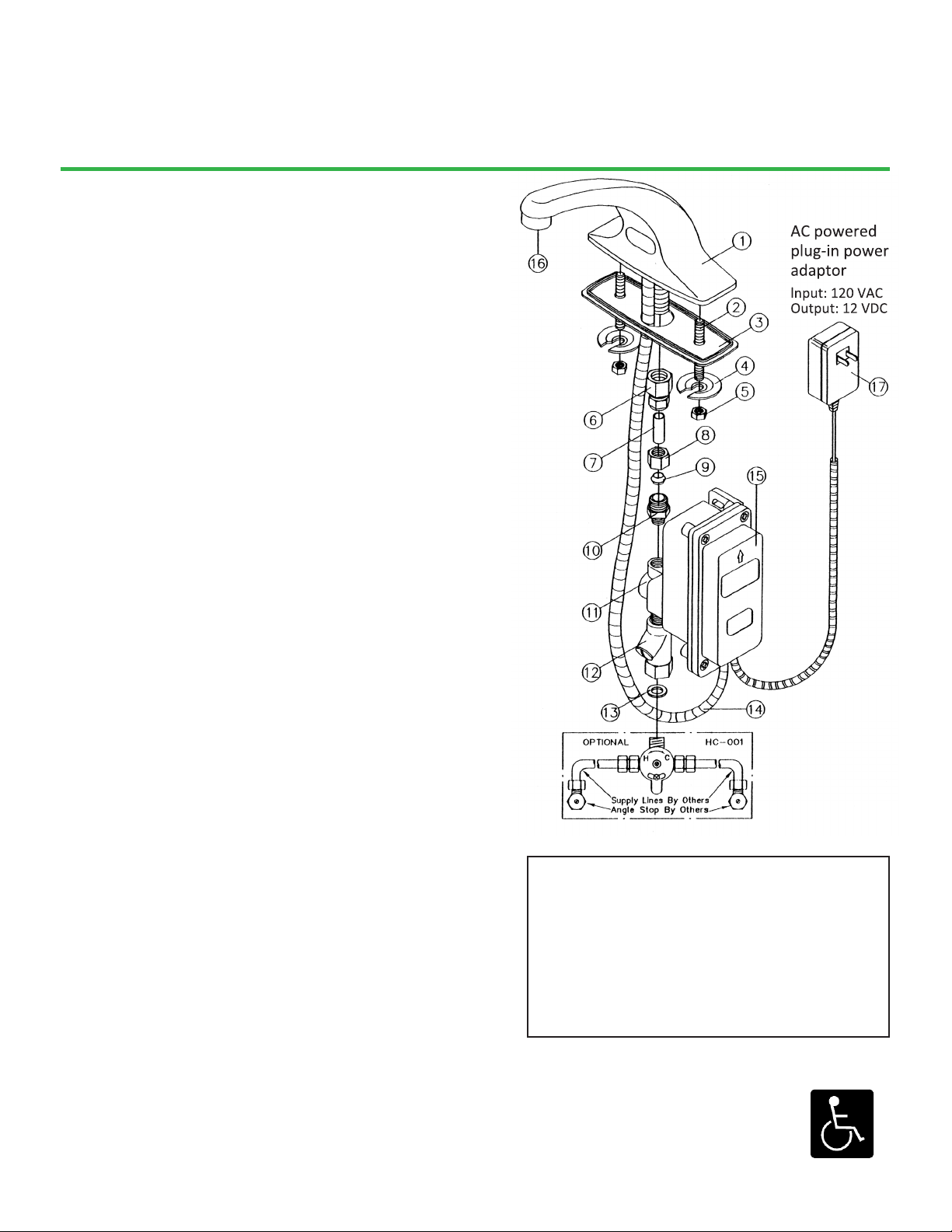
1. Faucet Body
2. Mounng Bolt
3. Mount Gasket
4. Sloed Washer
5. Mounng Nut
6. Compression Adapter
7. Supply Tube
8. Compression Nut
9. Compression ferrule
10. Compression Fing
11. Solenoid Valve
12. In-Line Filter
13. Nylon Washer
14. Sensor Eye Cable
15. Control Box
16. Aerator
17. Power Adapter
1. Prior to installaon, thoroughly ush all water lines and replace
stop washers, if required.
2. To ensure proper operaon, “DRY TEST” the faucet by plugging the
Sensor Eye Cable (14) into the matching connector on the PC board
inside of the Control Box (15).
a. AC Powered: Connect the Power Adapter (17) to the PC board
inside of the Control Box (15), then plug the Power Adapter
into a 120 V AC wall outlet. Place your hand in front of the
sensor eye and listen for a clicking sound. If there is no clicking
sound, call the factory.
b. Baery Powered: Properly install new baeries into the
baery holder and ensure the baery holder is connected to
the PC board. Place your hand in front of the sensor eye and
listen for a clicking sound. If there is no clicking sound, call the
factory.
3. Aer a successful “DRY TEST”, unplug the Sensor Eye Cable (14)
and Power Adapter (17) or baery holder from the PC board.
4. Aach the Compression Adapter (6), Supply Tube (7), and
Mounng Bolts (2) to the inlet on the Faucet Body (1).
5. Install the Mount Gasket (3) onto the Faucet Body and mount the
faucet onto the sink. Apply plumber’s puy to the boom of the
gasket and secure the faucet using the Sloed Washers (4) and
Mounng Nuts (5).
6. Reconnect the Sensor Eye Cable (14) and Power Adapter (17) or
baery holder as described in step #2 making sure the cables going
into the Control Box (15) are seated properly. Reinstall the cover
for the Control Box (15) and ghten the screws to ensure water
resistance. Coil excess cables and secure in a safe, dry area.
7. Aach the Solenoid Valve (11) to the Supply Tube (7) using the
supplied Compression Nut (8), Compression Ferrule (9), and
Compression Fing (10). Insert the Nylon Washer (13) into the
swivel nut loacted on the In-Line Filter (12).
a. Pre-tempered or cold water only: Use a union ng (not
supplied) to connect the supply line (not supplied) from the
supply stop to the In-Line Filter (12).
b. Tempered water: Aach an oponal Hydrotek HC-001 or HC-
003 mixing valveto the In-Line Filter (12). Connect the supply
lines (not supplied) to the mixing valve.
USE TEFLON TAPE FOR ALL CONNECTIONS, NO PIPE DOPE
8. Turn on the water and check for leaks. Plug the Power Adapter
(17) into a 120V AC outlet (for AC Powered). Push the reset buon
on the PC Board. Place hand in front of the sensor eye to acvate
water ow. Remove hands and the water should stop. If not, refer
to the troubleshoong guide.
9. Periodically clean the lter element in the In-Line Filter (12).
10. For minor adjustments, refer to instrucons located inside the
cover of the Control Box (15).
11. IMPORTANT: The stop valve should never be opened to the point
where the water ow exceeds the ow capability of the xture.
The xture must be able to accommodate the connuous water
ow from the faucet in the event of a failure. Should the xture
overow due to water exceeding the capability of the xture and/
or the drain pipe, Hydrotek will not be responsible for any damages.
Parts: