Hydro Tek 5000E Series Manual

Sensor Faucets and Flush Valves
OPERATION & MAINTENANCE MANUAL
5000E Series Faucet
5055 Forsyth Commerce Rd, Ste 124, Orlando, FL 32807
Phone (800) 922-9883 | Fax (866) 670-5580
www.hydrotekintl.com

5000E Series
U.S. Patent 6192530B1
AC or Baery Powered Sensor Operated Faucet
The 5000E Series faucet is an elegant piston operated
sensory faucet that provides a vandal resistant, no touch
lavatory soluon that promotes beer hygiene and energy
savings.
Designed to be easy to install and maintain, all major faucet
components are encased above deck, making for easier
access. The sensor included in this faucet is self adapng,
meaning manual adjustments are not necessary and the
innovave sensor placement eliminates ambient reecvity
issues.
• ADA Compliant. Meets all barrier free codes
• Conserves water and energy
• Easily installed in new or retrot applicaons
• Compevely priced for today’s commercial market
• Promotes cleanliness & hygiene
• Proven Hydrotek crasmanship and reliability
Available in:
DH-5000E-LR: Low Lead, AC Powered
DHE-5000E-LR: Low Lead, Baery Powered with Enduratek NEW!
Features:
• Proprietary Enduratek energy saving design allows up
to 1.5 million on/o cycles
• Vandal resistant faucet body with chrome plated,
solid metal construcon
• Faucet design allows for quick and simple installaon.
• Clam shell design allows for easy “above the deck”
access to all major faucet component parts.
• Slow closing solenoid valve provides reliable and
smooth operaon without water hammer.
• Available in AC powered and baery powered
versions.
• Unique, energy-saving design of electronics and
solenoid valve contributes to longer baery life.
• AC power input cable is armored and vandal resistant
(AC powered version).
• Sensor eye posioning eliminates ambient reecvity
issues.
• “Self-adapng” sensor distance adjustment
eliminates the need for manual sensor adjustments.
• 30 second me-out feature prevents accidental sink
overow.
• Built-in, replaceable lter screen reduces
maintenance costs.
• Low baery indicator light.
• Unique electronic control module allows for faucet
electronic component diagnoscs.
• Standard 0.5 GPM vandal resistant aerator.
• Single-hole deck mount with oponal 4” and 8” cover
plate for vandal resistant three point anchoring.
Sensor Faucets and Flush Valves

Hydrotek Automac Faucets
5000E Series
Deck Mounted / Non-mixing
Meets ANSI/ASME A112.18.1 M-1989
Operaon:
1. A connuous, invisible beam is emied from the sensor.
2. The faucet is acvated by placing hands under the spout within the
eecve range of the beam. Water starts to ow immediately for as
long as the user’s hands remain in the sensor range.
3. When hands are removed, the water ow stops. The sensor will
automacally reset and be ready for the next user.
4. In the baery powered version, a ashing red light will indicate a low
baery condion.
Specicaons:
Faucet Construcon: ............... Metal & chrome plated
Control Circuit:
Auto. Time-out: ................. 30 seconds
Sensor Range:................... Self adapng
Shut-o Delay: .................. 1 second
Solenoid Valve: .................... 6V DC, normally closed
Waage: ....................... 0.2W (idle), 3W (in use)
Operang Pressure: ............. 5 psi to 125 psi
Flow Control:...................... 0.5 GPM Laminar, vandal resistant
AC Mode
Power Adapter
Standard Plug-in:.................Input AC 120V 60 Hz
(UL/CSA)......................Output DC 7.5V, 0.8A/Class 2
Power Cable: ................Armored, vandal resistant
Oponal Mul-Unit Adapter: ........Serves up to 8 faucets
(UL/CSA)......................Input AC 120V, Output DC 7.5V, 3A
Baery Mode
Baery Powered Models:............(4) AA Alkaline Baeries
Enduratek Service Life:..............
1.5 million on/o cycles, up to 10 years
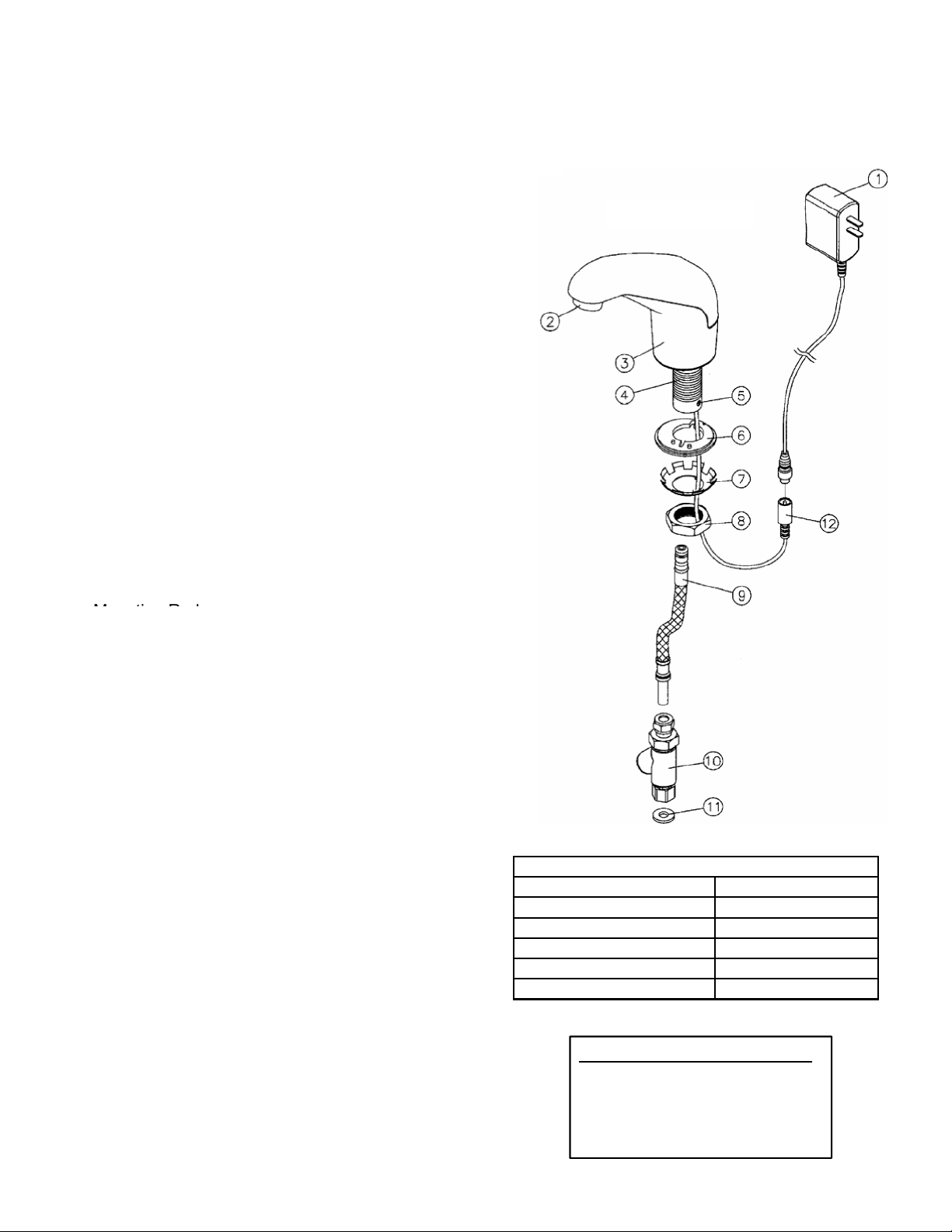
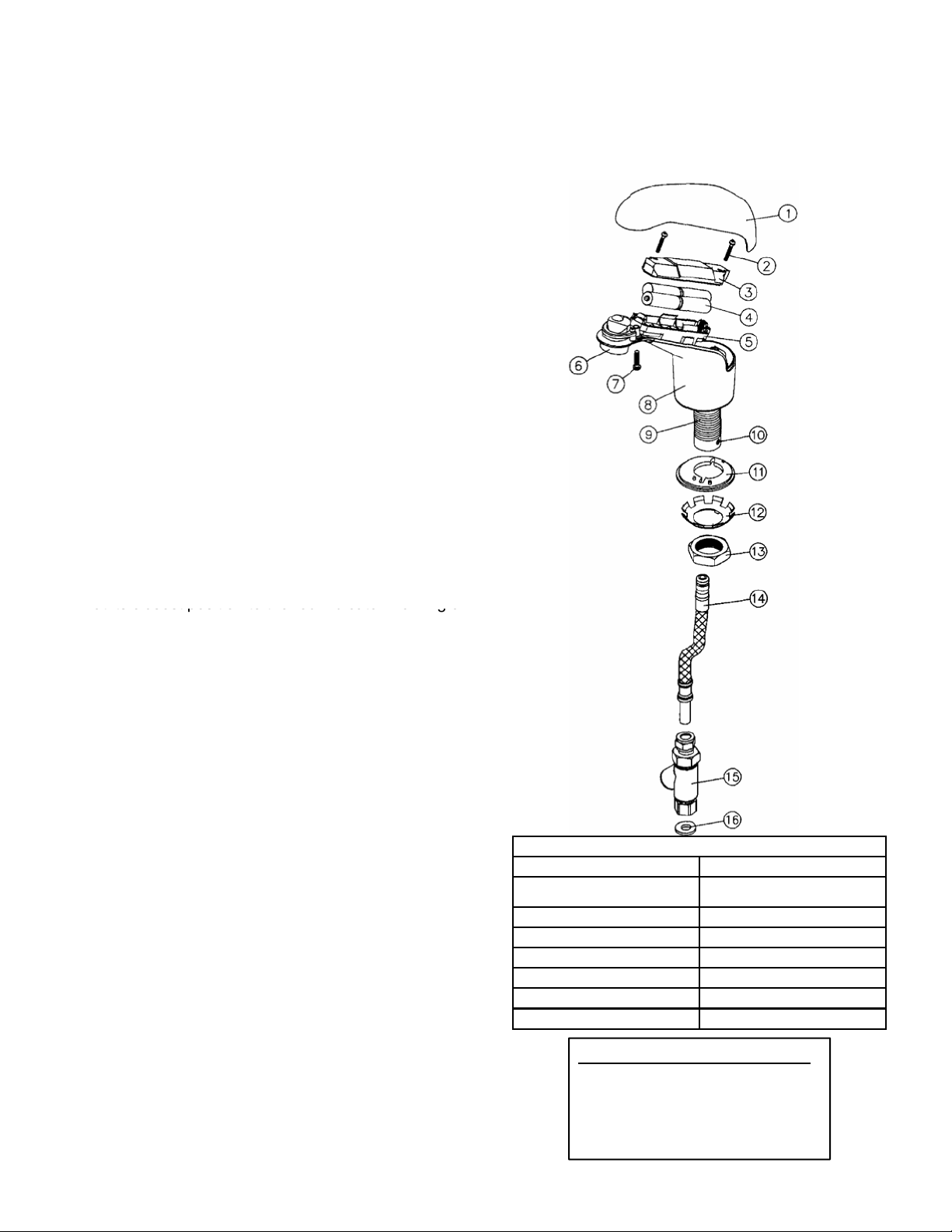
Package Includes:
(1) Faucet with sensor/solenoid
(1) 7.5V DC plug-in power adaptor (H-5000E & H-5000E-LR Only)
(2) Armored steel supply tube with lter
(1) Mounng lock nut and washer
(1) 0.5 GPM vandal resistant Rosee ow control
(4) AA Alkaline baeries (HB-5000E & HB-5000E-LR Only)
Dimensions:
Base Width (Outside Measurement) ..................2-3/8”
Base Depth ...................................... 2-3/8”
Faucet Height (Aerator to Base) ..................... 4-7/8”
Faucet Height Overall .............................. 6-1/2”
Depth (Center of Aerator to Center of Faucet Base) ..... 4-7/8”
Mounng Bolt Length.............................. 2-1/4”
Mounng Bolt Size ................................ 1-1/8”
Oponal Variaons and Accessories
• 1.5 GPM VR So Flow or 0.35, 2.2 GPM Laminar Flow Control
• 4” or 8” Centerset Cover Plate
• HC-010E Mul-Unit Voltage Adapter (AC Powered Only)
• HBL-04 Thermostac Mixing Valve with Checks
HYDROTEK INTERNATIONAL, INC.
5055 Forsyth Commerce Rd., Ste 124
Orlando, FL 32807
800.922.9883 (Phone)
866.670.5580 (Fax)
www.hydrotekintl.com
H-5000E (AC Powered)
HB-5000E (Baery Powered)

H-5000E
AC Powered Sensor Operated Mixing Faucet
Installaon Instrucons
INSTALLATION INSTRUCTIONS
Hydrotek Non
-
Mixing Automatic Faucet
(AC Powered)
Model H
-
5000E
1.
Prior
to
installing
this
faucet,
thoroughly
flush
all
water
lines
and
replace
stop
washers,
if
necessary
.
2.
To
ensure
proper
operation,
"
DRY
TEST
"
the
faucet
by
plugging
the
Power
Adapter
(
1
)
into
a
wall
outlet
and
connecting
the
Power
Adapter
output
lead
to
the
faucet
Input
Wire
Lead
(
12
)
.
The
faucet
should
immediately
perform
a
self
-
adjustment
and
diagnostic
function
.
If
you
see
the
indicator
light
flash
and
hear
a
clicking
sound,
proceed
to
the
next
step
.
If
there
is
no
flash
of
light
or
clicking
sound,
recheck
power
source
and
connections
.
3.
Unplug
Power
Adapter
(
1
)
from
the
wall
outlet
.
Disconnect
the
Power
Adapter
output
lead
from
the
faucet’s
AC
Input
Lead
(
12
)
.
4.
Rotate
the
Supply
Tube
Locking
Screw
(
5
)
fully
clockwise
.
Insert
the
end
of
the
Supply
Tube
(
9
)
(with
O
-
rings)
fully
into
the
bottom
of
the
Mounting
Rod
(
4
)
by
twisting
and
pushing
until
properly
seated
.
Rotate
Supply
Tube
Locking
Screw
(
5
)
counter
-
clockwise
to
lock
the
Supply
Tube
into
the
Mounting
Rod
.
HYDROTEK INTERNATIONAL, INC.
5055 Forsyth Commerce Rd.
, Ste.
124
Orlando, FL
32807
1.800.922.9883 (Phone)
1.866.670.5580 (Fax)
www.hydrotekintl.com
Part Number
Descriptions
1.
Power
adapter
7.
Star locking washer
2.
Flow control
8.
Mounting nut
3.
Faucet body
9.
Supply tube
4.
Mounting rod
10.
In
-
line filter
5.
Supply tube locking screw
11.
Nylon washer
6.
Gasket
12.
AC input lead
Mounting
Rod
.
5.
Attach
the
faucet’s
AC
Input
Lead
(
12
)
armored
cable
bracket
to
the
bottom
of
the
Mounting
Rod
(
4
)
using
the
existing
Mounting
Rod
screws
.
6.
Install
In
-
Line
Filter
(
10
)
onto
stop
valve
using
the
Nylon
Washer
(
11
)
.
7.
Unscrew
the
Mounting
Nut
(
8
)
from
the
Mounting
Rod
(
4
)
and
completely
remove
both
the
Mounting
Nut
(
8
)
and
the
Star
Locking
Washer
(
7
)
.
8.
From
above
the
deck,
carefully
feed
the
faucet’s
AC
Input
Lead
(
12
),
Supply
Tube
(
9
),
and
Mounting
Rod
(
4
)
into
the
deck
mounting
hole
and
seat
the
faucet
in
the
correct
mounting
location
.
9.
From
below
the
deck,
feed
the
AC
Input
Lead
(
12
)
and
Supply
Tube
(
9
)
through
the
keyed
Star
Locking
Washer
(
7
)
and
Mounting
Nut
(
8
)
.
Slide
the
Locking
Washer
and
Mounting
Nut
up
onto
the
Mounting
Rod
(
4
)
and
tighten
Mounting
Nut
on
the
Mounting
Rod
to
securely
lock
faucet
to
the
deck
.
10.
Connect
the
Supply
Tube
(
9
)
to
the
In
-
Line
Filter
compression
fitting
(
10
)
and
securely
tighten
.
11.
Connect
the
Power
Adapter
(
1
)
output
lead
to
the
faucet’s
AC
Input
Lead
(
12
)
.
Plug
the
Power
Adapter
into
the
electrical
wall
outlet
.
12.
Turn
water
on
and
check
for
leaks
.
Place
your
hands
under
the
faucet
spout
to
activate
water
flow
.
Remove
hands
and
water
should
stop
.

INSTALLATION INSTRUCTIONS
Hydrotek Non
-
Mixing Automatic Faucet
(Battery Powered)
Model HB
-
5000E
1.
Prior to installing this faucet, thoroughly
flush all water
lines and replace stop washers, if necessary.
2.
To ensure proper operation, " DRY TEST " the faucet
by loosening
the Cover Screw (7) and removing the
Top Cover (1). Loosen the Battery Holder Screws (2)
and remove the Battery Holder Cover (3). Insert
batteries into the Battery Holder (5) and reinstall the
Battery Holder Cover. The faucet should immediately
perform a self
-
adjusting and diagnostic function. If you
see the indicator light flash and hear a clicking sound,
proceed to the next step. If
there is no flash of light or
clicking sound, recheck batteries for correct
positioning.
3.
Remove Battery Holder Cover and batteries.
4.
Rotate the Supply Tube Locking Screw (10) fully
clockwise. Insert the end of the Supply Tube (14) (with
O
-
rings) fully into the bottom of the Mounting Rod (9)
by twisting and pushing until properly seated. Rotate
Supply Tube Locking Screw (10) counter
-
clockwise
until the red indicator marking on the Locking Screw is
at its closest position to the red indicator marking on
HYDROTEK INTERNATIONAL, INC.
5055 Forsyth Commerce Rd.
, Ste.
124
Orlando, FL
32807
1.800.922.9883 (Phone)
1.866.670.5580 (Fax)
www.hydrotekintl.com
Part Number
Descriptions
1.
Top cover
9.
Mounting rod
2.
Battery holder screws
(2)
10.
Locking screw for
supply tube
3.
Battery holder cover
11.
Rubber gasket
4.
AA Alkaline
Batteries (4)
12.
Star locking washer
5.
Battery holder
13.
Mounting nut
6.
Aerator
14.
Supply tube
7.
V.R.
screw for top cover
15.
In
-
line filter
8.
Faucet
body
16.
Nylon washer
at its closest position to the red indicator marking on
the Mounting Rod. This is necessary to ensure that the
Supply Tube has been properly locked into the
Mounting Rod.
5.
Install In
-
Line Filter (15) onto stop valve using the
Nylon Washer (16).
6.
Unscrew the Mounting Nut (13) from the Mounting Rod
(9) and completely remove both the Mounting Nut (13)
and the Star Locking Washer (12).
7.
From above the deck, carefully feed the faucet’s
Supply Tube (14) and Mounting Rod (9) into the deck
mounting hole and seat the faucet in the correct
mounting location.
8.
From below the deck, feed the Supply Tube (14) into
the keyed Star Locking Washer (12) and Mounting Nut
(13). Slide the Locking Washer and Mounting Nut up
onto the Mounting Rod (9) and tighten the Mounting
Nut on the Mounting Rod to securely lock the faucet to
the deck.
9.
Connect the Supply Tube (14) to the In
-
Line Filter
Compression Fitting (15) and securely tighten.
10.
Reinstall batteries and secure Battery holder Cover (3)
with the Battery Holder Screws (2).
11.
Reinstall Top Cover (1) and secure the faucet body
with Cover Screw (7).
12.
Turn water on and check for leaks. Place your hands
under the faucet spout to activate water flow. Remove
hands and water should stop.
HB-5000E
DC Powered Sensor Operated Mixing Faucet
Installaon Instrucons

5000E Series
Sensor Operated Mixing Faucet
Troubleshoong Guide
Normal Operaon: When power is connected, the faucet will immediately perform diagnosc funcon. You
will hear a clicking sound and see lights ash. When the user’s hands are placed under the spout, the light
will ash once and water will start to ow. Water ow will stop when hands are removed. The red indicator
light will ash when the baeries are low.
Turn the manual handle clockwise to increase temperature and counter-clockwise to decrease.
Problem Possible Cause To Diagnose Remedy
Faucet will not turn on:
Water not turned on Check water supply Turn water on
Power supply failure
No light, no clicking:
• Check baeries
• Check power adapter
Reinstall or replace baeries/
Replace power adapter
Low baery Light connues to ash Replace baeries
Electronic PCB / Sensor is
defecve
No light, no clicking:
• Reinsert baeries
• Reaach power adapter
Replace electronic PCB
Solenoid valve is clogged Solenoid is clicking but no water
is coming out Clean solenoid
In-line lter is clogged Open clean-out trap and check
lter screen Clean or replace lter screen
Solenoid coil is defecve
Insert new baeries or reaach
power adapter. Light blinks but
no solenoid is clicking
Replace solenoid coil
Flow control is clogged Open ow control device and
check Celan the ow control device
Faucet will not shut o,
has low glow, or drips:
The solenoid valve is normally closed. Turn o water and acvate the faucet. If there is a clicking
sound, the solenoid valve is dirty. If there is no clicking sound, then check the solenoid valve. If
the faucet is dripping, clean the solenoid valve.
IMPORTANT: Periodic maintenance is required for smooth and trouble-free operaon of this faucet.
For service and inquiry about available repair kits, please call Hydrotek Technical Support at (800) 922-
9883.

5000E Series
Sensor Operated Mixing Faucet
Maintenance Tasks
HCE-194 Solenoid Valve Assembly Replacement
1. Remove faucet Body Cover.
2. Remove baeries (baery powered faucets) or
unplug power adapater (AC powered faucets).
3. Loosen and remove the Baery Holder/Control
Module, making sure to disconnect all connectors.
4. Unscrew and remove the Solenoid Coil from the
Solenoid Valve Module.
5. Completely loosen the four screws securing the
Solenoid Valve Module. List the Solenoid Valve
Module from the faucet.
6. Install the new Solenoid Valve Module and
reassemble the faucet in reverse order. NOTE: When
installing the Solenoid Coil to the Solenoid Valve
Module, DO NOT over-ghten. Fit should be snug.
CONTROL MODULE (P.C. BOARD) REPLACEMENT
1. Remove faucet Body Cover.
2. Remove baeries (baery powered faucets) or
unplug power adapter (AC powered faucets).
3. Unplug the Baery Holder/Control Module
connector.
4. Loosen the two screws holding the Baery Holder/
Control Module and remove it.
5. Install the new Baery Holder/Control Module
ensuring the sensor eye is ed correctly to the
faucet body.
For further quesons, please call Hydrotek Technical
Support at (800) 922-9883.
Body Cover
Battery Holder
Control Module
Solenoid Coil
Solenoid Module

5000E Series
Sensor Operated Mixing Faucet
Assembly Parts
No Descripon Part Number
1Solenoid Module HCE-004
2Solenoid Coil HCE-019
3Solenoid Assembly HCE-194
4Control Module Assembly HCE-018A (AC)
HCE-018B (DC)
5Flexible Supply Tube HCE-026
6In-Line Filter HC-009A
7Filter Screen HC-020
8Aerator Connector HCE-006
9Copper Supply Tube HCE-016
10 Rubber Gasket HCE-022
11 Mounng Nut & Washer HCE-021
Please visit our website, www.hydrotekintl.com, for our
most current Products Pricing Sheet.
q
w
e
s
a
o
i
uy
t
r
This manual suits for next models
2
Table of contents
Other Hydro Tek Plumbing Product manuals

Hydro Tek
Hydro Tek HB-8000C series Manual

Hydro Tek
Hydro Tek 2603C Series Manual

Hydro Tek
Hydro Tek 1000C Series Manual

Hydro Tek
Hydro Tek 4100-LR Series Manual

Hydro Tek
Hydro Tek 5000EM Series Manual

Hydro Tek
Hydro Tek H-6300-LR Manual

Hydro Tek
Hydro Tek H-4000C-LR Manual

Hydro Tek
Hydro Tek HB8RFKC Series Manual