Hydro Tek 5000EM Series Manual

Sensor Faucets and Flush Valves
OPERATION & MAINTENANCE MANUAL
5000EM Series Faucet
5055 Forsyth Commerce Rd, Ste 124, Orlando, FL 32807
Phone (800) 922-9883 | Fax (866) 670-5580
www.hydrotekintl.com

5000EM Series
U.S. Patent 6192530B1
AC or Ba ery Powered Sensor Operated Faucet
The 5000EM Series faucet is an elegant piston operated
sensory faucet that provides a vandal resistant, no touch
lavatory solu on with hot/cold mixing and manual on/
o adjustments that promotes be er hygiene and energy
savings.
Designed to be easy to install and maintain, all major faucet
components are encased above deck, making for easier
access. The sensor included in this faucet is self adap ng,
meaning manual adjustments are not necessary and the
innova ve sensor placement eliminates ambient re ec vity
issues.
• ADA Compliant. Meets all barrier free codes
• Conserves water and energy
• Easily installed in new or retro t applica ons
• Compe vely priced for today’s commercial market
• Promotes cleanliness & hygiene
• Proven Hydrotek cra smanship and reliability
Available in:
H-5000EM-LR: Low Lead, AC Powered
HE-5000EM-LR: Low Lead, Ba ery Powered with Enduratek NEW!
Features:
• Proprietary Enduratek energy saving design allows up
to 1.5 million on/o cycles
• Vandal resistant faucet body with chrome plated,
solid metal construc on
• Faucet design allows for quick and simple installa on.
• Clam shell design allows for easy “above the deck”
access to all major faucet component parts.
• Integral faucet mixing valve (with built-in checks) &
manual on/o .
• “Above the deck” external or internal temperature
adjustment varia on.
• “Above the deck” manual on/o with external
temperature adjustment varia on.
• Slow closing solenoid valve provides reliable and
smooth opera on without water hammer.
• Available in AC powered and ba ery powered
versions.
• Unique, energy-saving design of electronics and
solenoid valve contributes to longer ba ery life.
• AC power input cable is armored and vandal resistant
(AC powered version).
• Sensor eye posi oning eliminates ambient re ec vity
issues.
• “Self-adap ng” sensor distance adjustment
eliminates the need for manual sensor adjustments.
• 30 second me-out feature prevents accidental sink
over ow.
• Built-in, replaceable lter screen reduces
maintenance costs.
• Low ba ery indicator light.
• Unique electronic control module allows for faucet
electronic component diagnos cs.
• Standard 0.5 GPM vandal resistant aerator.
• Single-hole deck mount with op onal 4” and 8” cover
plate for vandal resistant three point anchoring.
Sensor Faucets and Flush Valves

Hydrotek Automa c Faucets
5000EM Series
Deck Mounted / Non-mixing
Meets ANSI/ASME A112.18.1 M-1989
Opera on:
1. A con nuous, invisible beam is emi ed from the sensor.
2. The faucet is ac vated by placing hands under the spout within the
e ec ve range of the beam. Water starts to ow immediately for as
long as the user’s hands remain in the sensor range.
3. When hands are removed, the water ow stops. The sensor will
automa cally reset and be ready for the next user.
4. In the ba ery powered version, a ashing red light will indicate a low
ba ery condi on.
Specifi ca ons:
Faucet Construc on: . . . . . . . . . . . . . . . Metal & chrome plated
Mixing Valve (Built-in): . . . . . . . . . . . . . .
Control Circuit:
Auto. Time-out: . . . . . . . . . . . . . . . . . 30 seconds
Sensor Range:. . . . . . . . . . . . . . . . . . . Self adap ng
Shut-o Delay: . . . . . . . . . . . . . . . . . . 1 second
Solenoid Valve: . . . . . . . . . . . . . . . . . . . . 6V DC, normally closed
Wa age: . . . . . . . . . . . . . . . . . . . . . . . 0.2W (idle), 3W (in use)
Opera ng Pressure: . . . . . . . . . . . . . 5 psi to 125 psi
Flow Control:. . . . . . . . . . . . . . . . . . . . . . 0.5 GPM Laminar, vandal resistant
AC Mode
Power Adapter
Standard Plug-in:. . . . . . . . . . . . . . . . . Input AC 120V 60 Hz
(UL/CSA). . . . . . . . . . . . . . . . . . . . . . Output DC 7.5V, 0.8A/Class 2
Power Cable: . . . . . . . . . . . . . . . . Armored, vandal resistant
Op onal Mul -Unit Adapter: . . . . . . . . Serves up to 8 faucets
(UL/CSA). . . . . . . . . . . . . . . . . . . . . . Input AC 120V, Output DC 7.5V, 3A
Ba ery Mode
Ba ery Powered Models:. . . . . . . . . . . . (4) AA Alkaline Ba eries
Enduratek Service Life:. . . . . . . . . . . . . .
1.5 million on/off cycles, up to 10 years
Package Includes:
(1) Faucet with sensor/solenoid
(1) 7.5V DC plug-in power adaptor (H-5000EM & H-5000EM-LR Only)
(2) Armored steel supply tube with lter
(1) Moun ng lock nut and washer
(1) 0.5 GPM vandal resistant Rose e ow control
(4) AA Alkaline ba eries (HE-5000EM & HE-5000EM-LR Only)
Dimensions:
Base Width (Outside Measurement) . . . . . . . . . . . . . . . . . .2-3/8”
Base Depth . . . . . . . . . . . . . . . . . . . . . . . . . . . . . . . . . . . . . . 2-3/8”
Faucet Height (Aerator to Base) . . . . . . . . . . . . . . . . . . . . . 4-7/8”
Faucet Height Overall . . . . . . . . . . . . . . . . . . . . . . . . . . . . . . 6-1/2”
Depth (Center of Aerator to Center of Faucet Base) . . . . . 4-7/8”
Moun ng Bolt Length. . . . . . . . . . . . . . . . . . . . . . . . . . . . . . 2-1/4”
Moun ng Bolt Size . . . . . . . . . . . . . . . . . . . . . . . . . . . . . . . . 1-1/8”
Op onal Varia ons and Accessories
• 1.5 GPM VR So Flow or 0.35, 2.2 GPM Laminar Flow Control
• 4” or 8” Centerset Cover Plate
• HC-010E Mul -Unit Voltage Adapter (AC Powered Only)
• HBL-04 Thermosta c Mixing Valve with Checks
HYDROTEK INTERNATIONAL, INC.
5055 Forsyth Commerce Rd., Ste 124
Orlando, FL 32807
800.922.9883 (Phone)
866.670.5580 (Fax)
www.hydrotekintl.com
H-5000EM (AC Powered)
HB-5000EM (Ba ery Powered)
Adapts to internal or external
adjustments.
Manual on/o in external
adjustment mode.

H-5000EM
AC Powered Sensor Operated Mixing Faucet
Installaon Instrucons

INSTALLATION INSTRUCTIONS
Hydrotek Model HB/HE-5000EMLR-Mixing Faucet
Battery Powered
Part No. Description
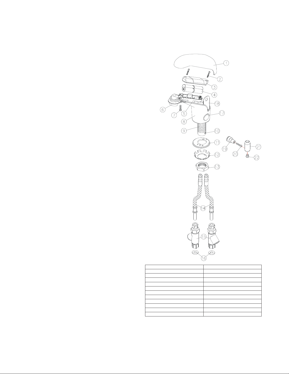
1. Top Cover 12. Star Locking Washer
2. Battery Holder Screws (2)
13. Mounting Nut
3. Battery Holder Cover
14. Supply Tube (2)
4. Batteries, AA Alkaline (4)
15.In-lineFilter (2)
5. Battery Holder
16. Nylon Washer (2)
6. Aerator
17. V.R. Access Cover
7. V.R. Screw, Top Cover
18. Lock
–
V.R. Access Cover
8. Body 19. Mix Shaft Extender
9. Mounting Rod
20. Screw, Mix Shaft Extender
10. Locking Screw, Supply Tube
21. Adjustor Handle
11. Gasket, Rubber 22. Screw, Adjustor Handle
0090H105
0417C
HYDROTEK INTERNATIONAL, INC.
5055 Forsyth Commerce Road, Suite#124
Orlando, FL 32807
1-800-922-9883
866-670-5580(Fax)
Prior to installing this faucet, thoroughly flush all water lines and replace
stop washers as may be required.
Rotate the Supply Tube Locking Screw (10) fully clockwise.Insert both
Supply Tube (14) ends ( with o-rings ) fully into the bottom of the
Mounting Rod (9) by twisting / pushing until properly seated. DO NOT
USE PIPE DOPE, USE TEFLON TAPE. Turn the Locking Screw (10)
counter-clockwise until the markings on the Mounting Rod and the Screw
are properly lined up.
Install in-line Filters (15) onto stop valves using nylon washer (16).
Unscrew Mounting Nut (13) from Mounting Rod (9) and completely
remove both Mounting Nut (13) and Star Locking Washer (12).
From above the deck, carefully feed the Supply Tubes (14) and
Mounting Rod (9) into deck mounting hole and seat faucet in correct
mounting location.
From below the deck, insert the Supply Tubes (14) into the keyed Star
Locking Washer (12) then Mounting Nut (13). Slide Locking Washer
and Mounting Nut up onto Mounting Rod (9) and tighten Mounting Nut
on Mounting Rod to securely lock faucet to the deck.
Connect Supply Tube (14) to the in-Line Filters compression fittings (15)
and securely tighten.
INSTALL BATTERIES and tighten the cover with Battery Holder Screws
(2).You should hear a clicking sound. Dry Test the faucet by placing
hands under the spout and you will hear another clicking sound. If not,
double check the batteries connections and positioning.
Turn water on and check for leaks.
Place your hands under the faucet spout, water should start to flow.
Remove your hands, water should stop. If the faucet is not functioning
properly,RE-INSERT BATTERIES and let the faucet “RESET” itself.
To adjust temperature in internal adjustment mode – open faucet body
top cover and remove Lock-V.R. Access Cover (18) and V.R. Access
Cover (17) from faucet body. With flat-bladed screwdriver rotate shaft
clockwise for colder and counter-clockwise for warmer water.
To install faucet external adjustor handle – open faucet body cover (1)
and remove Lock-V.R. Access Cover (18) and V.R. Access Cover (17)
from faucet body. Install Mix Shaft Extender (19) on Temp. Adjust Shaft
and secure with screw (20).
Securely attach Adjustor Handle (21) to Shaft Extender (19) with
screw (22).
To externally adjust temperature, rotate Adjustor Handle clockwise to
increase, counter-clockwise to decrease water temperature.
To turn faucet on manually – pull Adjustor Handle out from faucet body.
PUSH HANDLE IN toward faucet body to shut off water flow.
IMPORTANT: The stop valve should never be opened to the
point where the water flow exceeds the flow capability of the
fixture. The fixture must always be able to accommodate the
continuous water flow from the valve in the event of a valve
failure. Should the fixture overflow happen due to water
exceeding the capability of the fixture & or the drain pipe,
Hydrotek will not be responsible for any flood damages.
IMPORTANT:This product contains mechanical and/or electrical
components that are subject to normal wear.these components
should be checked regularly (1 year is recommended) and
replaced as needed to maintain the Faucets performance. Call
1-800-922-9883 for furtherdetails.
IMPORTANT:DO NOT use abrasives, acids or cleaning fluids
to clean the Hydrotek Faucet as they may dull the luster and
attack the chrome or special finishes. use only soap and water
then wipe with a clean cloth or towel.
1.
2.
3.
4.
5.
6.
7.
8.
9.
10.
11.
12.
13.
14.
15.
16.
17.
18.
HE-5000EM
DC Powered Sensor Operated Mixing Faucet
Installaon Instrucons

5000EM Series
Sensor Operated Mixing Faucet
Troubleshoong Guide
Normal Operaon: When power is connected, the faucet will immediately perform diagnosc funcon. You
will hear a clicking sound and see lights ash. When the user’s hands are placed under the spout, the light
will ash once and water will start to ow. Water ow will stop when hands are removed. The red indicator
light will ash when the baeries are low.
Turn the manual handle clockwise to increase temperature and counter-clockwise to decrease.
Problem Possible Cause To Diagnose Remedy
Faucet will not turn on:
Water not turned on Check water supply Turn water on
Power supply failure
No light, no clicking:
• Check baeries
• Check power adapter
Reinstall or replace baeries/
Replace power adapter
Low baery Light connues to ash Replace baeries
Electronic PCB / Sensor is
defecve
No light, no clicking:
• Reinsert baeries
• Reaach power adapter
Replace electronic PCB
Solenoid valve is clogged Solenoid is clicking but no water
is coming out Clean solenoid
In-line lter is clogged Open clean-out trap and check
lter screen Clean or replace lter screen
Solenoid coil is defecve
Insert new baeries or reaach
power adapter. Light blinks but
no solenoid is clicking
Replace solenoid coil
Flow control is clogged Open ow control device and
check Celan the ow control device
Faucet will not shut o,
has low glow, or drips:
The solenoid valve is normally closed. Turn o water and acvate the faucet. If there is a clicking
sound, the solenoid valve is dirty. If there is no clicking sound, then check the solenoid valve. If
the faucet is dripping, clean the solenoid valve.
IMPORTANT: Periodic maintenance is required for smooth and trouble-free operaon of this faucet.
For service and inquiry about available repair kits, please call Hydrotek Technical Support at (800) 922-
9883.

5000EM Series
Sensor Operated Mixing Faucet
Maintenance Tasks
HCE-194 Solenoid Valve Assembly Replacement
1. Remove faucet Body Cover.
2. Remove baeries (baery powered faucets) or
unplug power adapater (AC powered faucets).
3. Loosen and remove the Baery Holder/Control
Module, making sure to disconnect all connectors.
4. Unscrew and remove the Solenoid Coil from the
Solenoid Valve Module.
5. Completely loosen the four screws securing the
Solenoid Valve Module. List the Solenoid Valve
Module from the faucet.
6. Install the new Solenoid Valve Module and
reassemble the faucet in reverse order. NOTE: When
installing the Solenoid Coil to the Solenoid Valve
Module, DO NOT over-ghten. Fit should be snug.
CONTROL MODULE (P.C. BOARD) REPLACEMENT
1. Remove faucet Body Cover.
2. Remove baeries (baery powered faucets) or
unplug power adapter (AC powered faucets).
3. Unplug the Baery Holder/Control Module
connector.
4. Loosen the two screws holding the Baery Holder/
Control Module and remove it.
5. Install the new Baery Holder/Control Module
ensuring the sensor eye is ed correctly to the
faucet body.
For further quesons, please call Hydrotek Technical
Support at (800) 922-9883.
Body Cover
Battery Holder
Control Module
Solenoid Coil
Solenoid Module

5000EM Series
Sensor Operated Mixing Faucet
Assembly Parts
5000EM Series
Parts Breakdown
Sensor Faucets and Flush Valves
HYDROTEK INTERNATIONAL, INC.
5055 Forsyth Commerce Rd., Ste 124
Orlando, FL 32807
800.922.9883 (Phone)
866.670.5580 (Fax)
www.hydrotekintl.com
1
2
6
5
4
3
7
8
9
10
11
12
13
14
No Part Number Description
1 HCE-004 Solenoid Module
2 HCE-019 Solenoid Coil
3 HCE-018A/B Control Module
A=AC, B=Battery
4 HCE-028 Temp. Adjuster Rod
5 HCE-029 Temp. Handle Assembly
6 HCE-026* Flexible Supply Tube
7 HCE-009A In-Line Filter
8 HCE-020 Filter Screen
9 HCE-006 Aerator Connector
10 HB-003AMVR Aerator 0.5 GPM Male
Vandal Resistant
11 HCE-014 Top Cover
12 HCE-016 Copper Supply Tube
13 HCE-022 Rubber Gasket
14 HCE-021 Mounting Nut & Washer
Assembly
*For faucets purchased before 2008 or faucets that
use two o-rings on the supply tube, use HCE-015.
This manual suits for next models
2
Table of contents
Other Hydro Tek Plumbing Product manuals

Hydro Tek
Hydro Tek 1000C Series Manual

Hydro Tek
Hydro Tek 2603C Series Manual

Hydro Tek
Hydro Tek 5000E Series Manual

Hydro Tek
Hydro Tek H-6300-LR Manual

Hydro Tek
Hydro Tek HB-8000C series Manual

Hydro Tek
Hydro Tek H-4000C-LR Manual

Hydro Tek
Hydro Tek 4100-LR Series Manual

Hydro Tek
Hydro Tek HB8RFKC Series Manual