Hydro Tek 2603C Series Manual

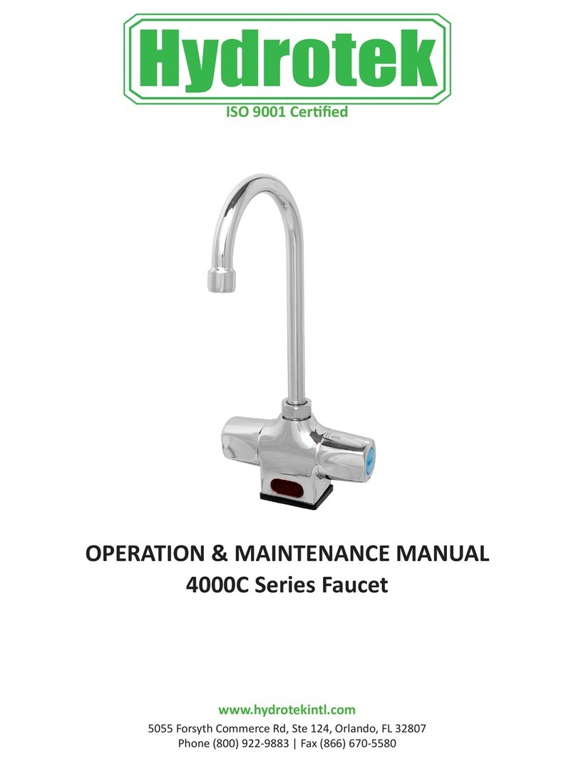
OPERATION & MAINTENANCE MANUAL
2603C Series Faucet
5055 Forsyth Commerce Rd, Ste 124, Orlando, FL 32807
Phone (800) 922-9883 | Fax (866) 670-5580
www.hydrotekintl.com
Sensor Faucets and Flush Valves

Revised 7/6/20
2603C Series
AC or Baery Powered Sensor Operated Faucet
Sensor Faucets and Flush Valves
5055 Forsyth Commerce Rd Ste 124, Orlando, FL 32807
Phone: 800.922.9883 | Fax: 866.670.5580 | hydrotekintl.com
The informaon contained within this document subject to change without noce
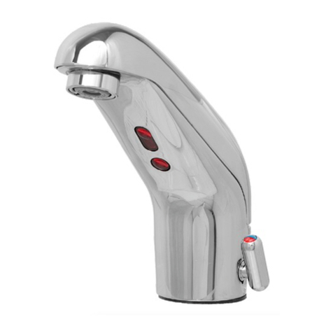
The 2603C Series faucet is a single-hole deck mounted, piston
operated sensory faucet that provides a vandal resistant, no touch
lavatory soluon that promotes beer hygiene and energy savings.
• ADA Compliant. Meets all barrier free codes
• Conserves water and energy
• Easily installed in new or retrot applicaons
• Compevely priced for today’s commercial market
• Promotes cleanliness & hygiene
• Proven Hydrotek crasmanship and reliability
Available Models
FH-2603C-LR: Lead Free, AC Powered
FHB-2603C-LR: Lead Free, Baery Powered
FH-2603C-LRDC: Lead Free, AC Powered with Baery
Backup
Features
• ACCU-SENSE adjustable sensor eyes.
• Chrome plated, solid brass construcon.
• Wall mountable, waterproof control box with armored, vandal
resistant control and power cables.
• Preset/adjustable sensor range of 6” - 30” for various
installaon requirements.
• Standard automac me-out feature. Preset at 30 seconds, but
adjustable to 10, 30, or 60 seconds. Prevents accidental sink
overow.
• Shut-o delay is adjustable from 1 (preset) to 8 seconds.
• Solid brass body with single hole deck mounng. Oponal 4” or
8” cover plate for 3 point anchoring.
• Includes in-line lter with clean-out trap to reduce maintenance
costs.
• All parts are eld-replaceable to ensure quick and easy repair.
• Same faucet-eld switchable to AC or baery powered.
• AC with DC backup models automacally switch to baeries
during a power outage
• Slow closing, piston-operated solenoid valve provides reliable
and smooth operaon without water hammer.
• Superior VSI silicone elastomer piston seals are unaected by
chlorine, chloromines, or ammonia.
• Standard 1.5 or 0.5 GPM Laminar ow control for water
conservaon and annual savings.
• Control module allows a unique self-check of all electrical
components.
Compliances & Cercaons
• ADA Compliant
• ASME A112.18.1
• NSF/ANSI Standard 372 - Lead Free Compliant
Special Finishes
• Addional Finishes Upon Request

Revised 7/6/20
2603C Series
AC or Baery Powered Sensor Operated Faucet
Sensor Faucets and Flush Valves
5055 Forsyth Commerce Rd Ste 124, Orlando, FL 32807
Phone: 800.922.9883 | Fax: 866.670.5580 | hydrotekintl.com
The informaon contained within this document subject to change without noce
Specicaons:
Faucet Construcon: - Solid brass, chrome plated
Control Circuit: - Solid state, AC or baery, switchable
Auto. Time-out: - Preset at 20 seconds and adjustable
to 10, 30, or 60 seconds
Line Purge (request only): - 2 minute run every 12 hours or 24 hours
Scrub Mode Delay (request only): - 60, 120, 180 seconds
Sensor Range: - Preset and adjustable
Shut-o Delay: - Presets and adjustable from 1-8 seconds
Control Cable: - Armored, vandal resistant
Solenoid Valve: - 6V DC, normally closed
- Waage: 0.4W (idle), 5W (in use)
- Operang Pressure: 5 psi to 125 psi
Flow Control: - 1.5 or 0.5 GPM, vandal resistant
AC Mode
Power Adapter
Standard Plug-in: - Input AC 120V 60 Hz or 220V
(UL/CSA) - Output DC 12V, 0.8A/Class 2
Power Cable: - Armored, vandal resistant
Oponal Mul-Unit Adapter: - Serves up to 8 faucets
(UL/CSA) - Input AC 120V, Output DC 12V, 3A
Baery Mode
Baery Powered Models: - (4) AA Alkaline Baeries
Baery Service Life: - 400,000 on/o cycles, up to 4 years
Package Includes:
(1) Faucet with electronic sensor
(1) Control box w/6V DC solenoid
(1) 12V DC plug-in power adaptor (H-2603C, -DC, -LR, and –LRDC only)
(1) In-line lter with clean-out trap
(1) Copper supply tube, 3/8”
(1) Mounng hardware
(1) 1.5 GPM vandal resistant ow control
(4) AA Alkaline baeries (HB-2603C, -LR; H-2603C-DC, -LRDC only)
(1) Baery holder (HB-2603C, -LR; H-2603C-DC, -LRDC only)
Dimensions:
Base Width (Outside Measurement) 2-3/8”
Base Depth 2-3/8”
Faucet Height (Aerator to Base) 3-3/8”
Faucet Height Overall 4-1/2”
Depth (Center of Aerator to Center of Faucet Base) 4-9/16”
Mounng Bolt Length 2-1/4”
Mounng Bolt Paern Single-hole mount
Oponal Variaons and Accessories
• 0.35, 0.5, 2.2 GPM Laminar Flow, 1.5 GPM VR So-Flow Aerator
• 4” or 8” Centerset Cover Plate
• HC-010 Mul-Unit Voltage Adapter (AC Powered Only) - 8 units
• HC-0104 Mul-Unit Voltage Adapter (AC Powered Only) - 4 units
• HC-001 Mixing/Check Valve (Mechanical)
• HBL-04 Thermostac Mixing Valve with Checks
Deck Mounted

2603C Series
DC Powered Sensor Operated Mixing Faucet
Installaon Instrucons
ISO 9001 Certified
2603C Series
Sensor Operated Faucet
Installation Instructions
1.
Prior to installation, thoroughly flush all water lines and replace
stop washers, if required.
2.
To ensure proper operation, “DRY TEST” the faucet by plugging the
Sensor Eye Cable (11) into the matching connector on the PC board
inside of the Control Box
(12).
a.
AC Powered: Connect the Power Adapter (14) to the PC
board inside of the Control Box (12), then plug the Power
Adapter into a 120 V AC wall outlet. Place your hand in front of
the sensor eye and listen for a clicking sound. If there is no
clicking sound, call the factory.
b.
Battery Powered: Properly install new batteries into the
battery holder and ensure the battery holder is connected to
the PC board. Place your hand in front of the sensor eye and
listen for a clicking sound. If there is no clicking sound, call the
factory.
3.
After a successful “DRY TEST”, unplug the Sensor Eye Cable (11)
and Power Adapter (14) or battery holder from the PC board.
4.
Attach the Supply Tube (6), and Mounting Bolts (2) to the inlet on
the Faucet Body (1).
5.
Install the Mount Gasket (3) onto the Faucet Body and mount the
faucet onto the sink. Apply plumber’s putty to the bottom of the
gasket and secure the faucet using the Slotted Washers (4) and
Mounting Nuts (5).
6.
Reconnect the Sensor Eye Cable (11) and Power Adapter (14) or
battery holder as described in step #2 making sure the cables going
into the Control Box (12) are seated properly. Reinstall the cover for
the Control Box (12) and tighten the screws to ensure water
resistance. Coil excess cables and secure in a safe, dry area.
7.
Attach the Solenoid Valve (8) to the Supply Tube (6) using the
Compression Fitting (7). Insert the Nylon Washer (10) into the
swivel nut located on the In-Line Filter (9).
a.
Pre-tempered or cold water only: Use a union fitting (not
supplied) to connect the supply line (not supplied) from the
supply stop to the
In-Line Filter (9)
.
b.
Tempered water: Attach an optional Hydrotek HC-001 or HC-
003 mixing valve to the In-Line Filter (9). Connect the supply
lines (not supplied) to the mixing valve.
Parts:
AC powered
plug-in power
adaptor
Input: 120 VAC
Output: 15VDC
USE TEFLON TAPE FOR ALL CONNECTIONS, NO PIPE DOPE
8.
Turn on the water and check for leaks. Plug the Power Adapter
(14) into a 120V AC outlet (for AC Powered). Push the reset button
on the PC Board. Place hand in front of the sensor eye to activate
water flow. Remove hands and the water should stop. If not, refer
to the troubleshooting guide.
9.
Periodically clean the filter element in the
In-Line Filter(9)
.
10.
For minor adjustments, refer to instructions located inside the
cover of the Control Box ( 1 2 ).
11.
IMPORTANT:
The stop valve should never be opened to the
point
where the water flow exceeds the flow capability of the
fixture. The fixture must be able to accommodate the continuous
water flow from the faucet in the event of a failure. Should the
fixture overflow due to water exceeding the capability of the fixture
and/ or the drain pipe, Hydrotek will not be responsible for any
damages.
1. Faucet Body 8. Solenoid Valve
2. Mounting Bolt 9. In-Line Filter
3. Mount Gasket 10. Nylon Washer
4. Slotted Washer 11. Sensor Eye Cable
5. Mounting Nut 12. Control Box
6. Supply Tube 13. Aerator
7. Compression Fitting 14. Power Adapter
HYDROTEK INTERNATIONAL, INC.
5055 Forsyth Commerce Rd., Ste 124
Orlando, FL 32807
800.922.9883 (Phone)
866.670.5580 (Fax)
www.hydrotekintl.com
0090H062-2
2603C Series
Sensor Operated Mixing Faucet
Troubleshoong Guide
Normal Operaon: When power is connected, the faucet will immediately perform diagnosc funcon. You
will hear a clicking sound and see lights ash. When the user’s hands are placed under the spout, the light
will ash once and water will start to ow. Water ow will stop when hands are removed. The red indicator
light will ash when the baeries are low.
Turn the manual handle clockwise to increase temperature and counter-clockwise to decrease.
Problem Possible Cause To Diagnose Remedy
Faucet will not turn on:
Water not turned on Check water supply Turn water on
Power supply failure
No light, no clicking:
• Check baeries
• Check power adapter
Reinstall or replace baeries/
Replace power adapter
Low baery Light connues to ash Replace baeries
Electronic PCB / Sensor is
defecve
No light, no clicking:
• Reinsert baeries
• Reaach power adapter
Replace electronic PCB
Solenoid valve is clogged Solenoid is clicking but no water
is coming out Clean solenoid
In-line lter is clogged Open clean-out trap and check
lter screen Clean or replace lter screen
Solenoid coil is defecve
Insert new baeries or reaach
power adapter. Light blinks but
no solenoid is clicking
Replace solenoid coil
Flow control is clogged Open ow control device and
check Celan the ow control device
Faucet will not shut o,
has low glow, or drips:
The solenoid valve is normally closed. Turn o water and acvate the faucet. If there is a clicking
sound, the solenoid valve is dirty. If there is no clicking sound, then check the solenoid valve. If
the faucet is dripping, clean the solenoid valve.
IMPORTANT: Periodic maintenance is required for smooth and trouble-free operaon of this faucet.
For service and inquiry about available repair kits, please call Hydrotek Technical Support at (800) 922-
9883.
Care and Cleaning Instrucons:
• WARNING! Using abrasive or chemical cleaners will damage the chrome or decorave nishes.
• Use only soap and water to clean the nish, then wipe dry with a clean cloth.
• If chemical cleaners are used for other parts of the lavatory, ensure that the faucet is protected from
potenal contact from those cleaners.

2603C Series
Sensor Operated Mixing Faucet
Solenoid Valve Cleaning
1. Turn o water supply at stop valve.
2. Remove control box (if possible) to gain access
to the solenoid valve.
3. Remove four Screws (#1) and separate the
valve from the box.
4. Remove four Coil Screws (#2) and separate Coil
(#3) from Valve Seat (#4).
5. Clean or replace Control Disc (#5), Disc Spring
(#6), Piston, Piston Spring, and check the Piston
Sleeve for corrosion.
6. Re-install all parts in same order as the diagram
below.
7. Re-install solenoid on the control box and re-
mount box in water line.
8. Check and clean Filter Screen (#24) in Filter
Body (#22).
9. Reset P.C. Board and make sure solenoid clicks
open and thumps closed.
10. Turn on water and check for leaks and proper
operaon.
(For further quesons, please call Hydrotek Tech
Support at 1-800-922-9883 ext. 103)
1
2
3
4
5
6

2603C Series
Sensor Operated Mixing Faucet
Control Module Sengs
IMPORTANT: Always push the Reset Buon aer any adjustments
1 2 3 4 5 6 7 8
Factory Preset
= Switch Position
Shut O Time Delay (Aer hands are removed)
Sw1 Sw2 Sw3 Delay
On On On 1 Sec
On On O 2 Sec
On O On 3 Sec
On O O 4 Sec
O On On 5 Sec
O On O 6 Sec
O O On 7 Sec
O O O 8 Sec
Automac Time O (maximum run me aer acvaon)
Sw4 Sw5 Time O
On On OFF
On O 15 Sec
O On 30 Sec
O O 60 Sec
Sensor Distance
Sw6 Mode Distance
On Std 4” - 12”
O Enhanced 10” - 12”
To increase distance, turn adjuster CLOCKWISE
To decrease distance, turn adjuster COUNTER-CLOCKWISE
Faucet Switch - DO NOT TOUCH
Sw7 Sw8 Mode
On O Auto Faucet

2603C Series
Sensor Operated Mixing Faucet
Assembly Parts
1
2
3
4
5
No Descripon Part Number
1PCB Module HCC-011B
2Sensor Eye and Cable HCC-030
3Solenoid Valve Repair Kit HCB-017A
4Solenoid Assembly HCC-005
5Solenoid Coil HCC-019
Baery Holder HCC-103A
Plug-in Adapter HCC-008B
This manual suits for next models
3
Table of contents
Other Hydro Tek Plumbing Product manuals

Hydro Tek
Hydro Tek 5000E Series Manual

Hydro Tek
Hydro Tek H-4000C-LR Manual

Hydro Tek
Hydro Tek 5000EM Series Manual

Hydro Tek
Hydro Tek HB-8000C series Manual

Hydro Tek
Hydro Tek 4100-LR Series Manual

Hydro Tek
Hydro Tek 1000C Series Manual

Hydro Tek
Hydro Tek HB8RFKC Series Manual

Hydro Tek
Hydro Tek H-6300-LR Manual
Popular Plumbing Product manuals by other brands

Krowne
Krowne Royal Series installation manual

Moen
Moen LEGEND MOENTROL 3189 Specifications

Spectrum Brands
Spectrum Brands Pfister Verve LG15-MDS1 Quick installation guide

Moen
Moen EVA T2131BN Specifications

BELLOSTA
BELLOSTA bambu 0400/Q Installation instruction

Plasson
Plasson EF Saddle installation instructions