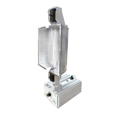
Hydrofarm Phantom DE User manual

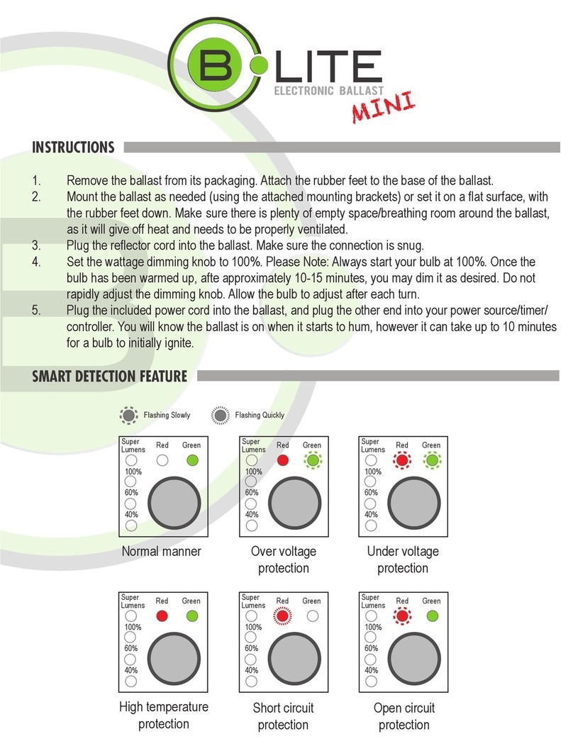
INSTRUCTIONS
DOUBLE-ENDED DIGITAL BALLAST
PHB4010

INSTRUCTIONS
OVERVIEW
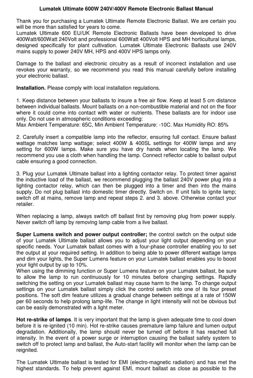
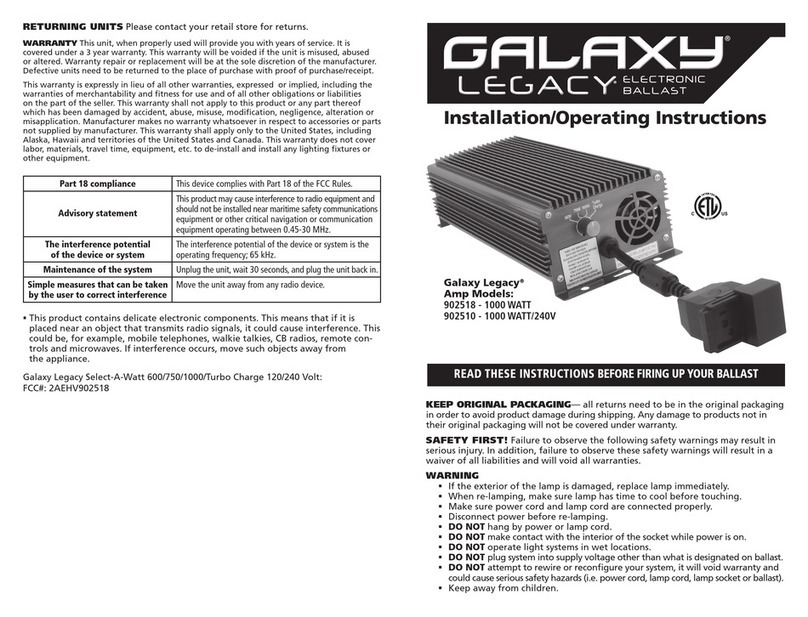
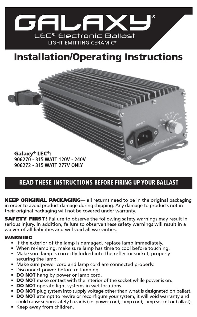
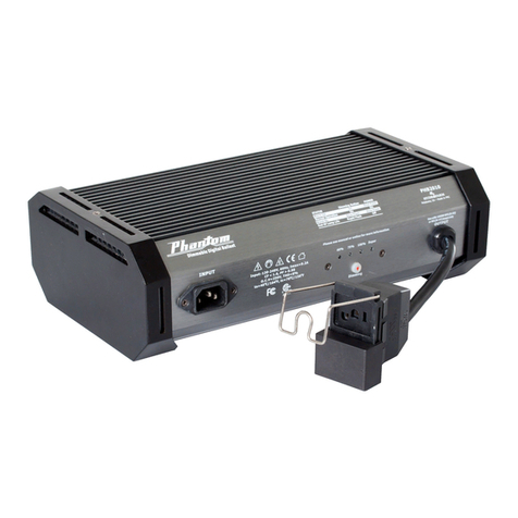
The Phantom Ballast Commercial DE is an ideal ballast choice for ecient growing. It was
created with state-of-the-art microprocessor technology to ulize the industry’s double-
ended 1000W HPS lamps. It operates on a 120/208/240V, 50/60 Hz power supply.
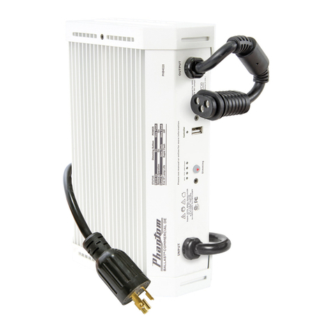
This ballast (and all 40 Series Phantom Ballasts) includes a Control Port on the side panel
which allows connecon to and data communicaon with the Autopilot PX1 Lighng
Controller via USB. Use with the PX1 is oponal—the 40 series ballasts operate perfectly
with standard manual control when not connected to a PX1. The power cord for the 40
Series ballasts now includes a ferrite collar which suppresses radio frequency interference.
WARNINGS
• This ballast and the Control Port are compatible only with the Autopilot PX1 Lighting
Controller. Do not connect any other device to the Control Port. Any attempt to
connect it to an unrelated device or control it with an incompatible controller may
result in damage to the ballast and will void the warranty.
• Use this ballast in greenhouses or indoor applications only. Position it in an area
away from excessive heat or contact with liquids.
• This ballast does not rely on the luminaire enclosure for protection against accidental
contact with live parts.
• For remote operations, use this ballast with a maximum lamp cord of 15 feet.
• Disconnect the ballast from the power supply before performing any maintenance,
lamp changes, or other modifications.
• Contact the retailer or distributor for service if the ballast does not work after
confirming the power connection, output connection, and bulb operation.
• Opening the ballast will void the warranty.
• Lamps with built-in ignitors will not work with this ballast. Not for use with external
ignitors.
• Always disconnect ballast’s power cord before moving the unit or changing lamps.
• This product may cause interference to radio equipment and should not be installed
near maritime safety communications equipment or other critical navigation or
communication equipment operating between 0.45-30 MHz.
INSTALLATION AND CONNECTION
For proper lamp break-in, we recommend that you run the ballast and bulb at 100%
power for at least 12 straight hours aer inial startup. This will improve lamp life and
performance.
1. Find a suitable locaon for the ballast with sucient cooling and away from any heat
source.
2. Install the lamp rmly into the lamp socket of the reector and connect the Lock &
Seal lamp cord to the ballast.
3. Remove the power cord from the box. Plug the power cord into the power source
(electrical outlet).
4. Plug the power cord into the power source (electrical outlet).
5. Once lamp has red, set your desired dimming rao. Please note that the ballast
dims or raises output gradually to protect the lamp, so you might not see an instant
increase upon changing your output percentage.
• Using the template on the left, mark the mounting screw positions on the wall.
Screws need to be 145mm apart to ensure the screw head can be inserted into the
hole on the back of the ballast. It is recommended that the screws be mounted in a
PRECISION WALL MOUNT GUIDE
Mark Drill HolesMark Drill Holes
145mm

3
wall stud. If that is not possible, please use drywall anchors rated for at least 15 pounds.
• Install the screws (not provided) into the stud. Install to the proper depth of 15mm.
• Slide the ballast onto the screws.
• We recommend that you mount the ballast vertically, with the output connector towards the bottom, for
optimal cooling.
• Aside the vertical hanging way stated above, there are three other ways to utilize this ballast. Simply sit it
on the floor in a convenient location; use the holes in the end plate flanges to hard-mount the ballast into
place with bolts (not provided); or hang the ballast with attached style reflectors (instructions included within
reflector package).
NOTES ON DIMMING
• When a USB cable is connected to the ballast’s control port, manual dimming is defeated. The power-level
LEDs over the Dimming button on the rear panel will go dark, and the LED next to the control port will go on.
When/if the USB cable is disconnected from the control port, dimming control is returned to the Dimming
button after a short delay, indicated by those LEDs becoming active again after start-up.
• Press the dimming button to cycle through the dimming levels. The appropriate LED indicator will light up to
indicate selected dimming level (60%, 75%, 100%, Super).
• This ballast has built-in hot-restrike programming to protect the lamp and ballast in the event of the ballast
turning off unexpectedly. The ballast will not attempt to restart a hot lamp for at least 15 minutes. If your
lamp fails to start immediately, DO NOT cycle the power on and off. This can damage the lamp and ballast.
If after 30 minutes your lamp is still not lit, shut off power to the ballast, and reconnect. This will begin the
startup sequence again.
Main Voltage – Rated input voltage range for the ballast.
– The acceptable operang range for input voltage to the ballast. Deviaons from the
rated numbers may result in decreased ballast performance and addional case generated heat.
– Maximum possible waage draw of the ballast.
Amperage – Input current or draw.
– A measurement of how eecvely the ballast converts electrical current to useful power output, in
this case, output to the lamp. Power factor is measured between 0-1; the closer you get to 1, the more eecve the
circuit is said to be. The ballast’s power factor is greater than .99.
Ignitor Voltage – Ballast output during ignion sequence.
– A measurement of all harmonics present in a circuit. The higher the number, the
more stress is applied to internal parts, the lamp, and the power grid. Generally, a number below 10% is considered
desirable in an electronic ballast applicaon.
– A measurement of how “clean” the ballast power output wave is. A perfectly clean output sine
wave would have a CF of 1.414. Given that some harmonics must exist in an electrical system, the crest factor must
always be higher than 1.414. Therefore, the closer the ballast is to a CF of 1.414, the easier it is on the lamp.
– Maximum rated ambient temperature for the ballast area. Excessive ambient
temperature can result in ballast failure, safety shutdown, or lamp failure.
– Maximum temperature that the case of the ballast should reach. If the case temperature
exceeds this number, the ballast may be malfunconing or the ambient temperature may exceed the rang.
– Ferrites are usually non-conducve ferrimagnec ceramic compounds derived from iron oxides. Ferrite
cores are commonly incorporated as “collars” or “beads” on power cables of electronic equipment to prevent high
frequency electrical noise (radio frequency interference) from exing or entering the equipment.
INSTRUCTIONS

WARRANTY
Hydrofarm warrants the PHB4010 to be free from defects in materials and workmanship. The warranty term is for
3 years beginning on the date of purchase. Misuse, abuse, or failure to follow instrucons is not covered under this
warranty. Hydrofarm will, at our discreon, repair or replace the PHB4010 covered under this warranty if it is returned
to the original place of purchase. To request warranty service, please return the PHB4010, with original sales receipt
and original packaging, to your place of purchase. The purchase date is based on your original sales receipt.
GARANTIE LIMITÉE
Hydrofarm garant que PHB4010 ne présente pas de défauts de matériel ni de fabricaon. La garane est en
vigueur 3 ans à parr de la date d’achat. Cee garane ne couvre pas l’ulisaon incorrecte, l’abus ou le non
respect de la noce. Hydrofarm, selon ses critères, réparera ou remplacera PHB4010 couvert par cee garane
s’il est renvoyé au centre original d’achat. Pour demander le service de garane, renvoyer PHB4010, avec le cket
d’achat et l’emballage originaux, au centre d’achat. La date d’achat est indiquée sur le cket d’achat original.
GARANTÍA LIMITADA
Hydrofarm garanza que PHB4010 no presenta defectos en los materiales ni la fabricación. La vigencia de la
garana es 3 años que comienza en la fecha de compra. Esta garana no cubre el uso erróneo, el abuso o el
incumplimiento de las instrucciones. Hydrofarm, según si criterio, reparará o sustuirá PHB4010 incluido en esta
garana si se devuelve al centro original de compra. Para solicitar el servicio de garana, devuelva PHB4010, con el
que de compra y el embalaje originales, a su centro de compra. La fecha de compra se basa en su que de compra
original.
Model Main Voltage Operating Voltage
Range
Max Input
Power Output Power Settings Power
Factor
Ignitor
Voltage THD CF ta tc
Modèle Tension
principale
Plage de tension de
fonctionnement
Puissance
absorbée max
Réglages de la puissance
de sortie
Facteur de
puissance
Tension
d’allumage THD CF ta tc
Modelo Voltaje principal Rango de voltaje de
funcionamiento
Max. potencia
de entrada
Configuración de la potencia
de salida
Factor de
potencia
Voltaje del
ignitor THD CF ta tc
PHB4010
120/208/240V 108-265V 1246W Super/100%/75%/60% > 0.98 4.0 kV < 8% 1.414-1.6 40°C/104°F 70°C/158°F
Model Imax 120/208/240V Super Boost 120/208/240V 100% 120/208/240V 75% 120/208/240V 60% 120/208/240V
PHB4010 10.5/6.1/5.3 10.2/5.9/5.1 8.9/5.1/4.5 6.7/3.9/3.3 5.4/3.1/2.7
STATUS / ÉTAT / ESTADO DIMMING BUTTON / BOUTON DEVARIATION /
BOTÓN DE REGULACIÓN
SELECTED POWER LED / LED D’ALIMENTATION SÉLECTIONNÉE
/ LED ENCENDIDO
Warm Up / Mise en température / Proceso de encendido On / sur / en Slow Flash / Clignotement lent / Parpadeo lento
Normal Operation / Fonctionnement normal / Funcionamiento normal On / sur / en On / sur / en
Stand By / Mode veille / Modo espera Slow Flash / Clignotement lent / Parpadeo lento Slow Flash / Clignotement lent / Parpadeo lento
Ballast Fault / Anomalie du ballast / Error balasto Off / off / apagado Off / off / apagado
Lamp Fault / Anomalie de la lampe / Error lámpara Off / off / apagado
Rapid Flash / Clignotement rapide / Parpadeo rápido
End of Life Lamp Indicator /Témoin de fin de vie de la lampe / Indicador
de final de la vida útil de la lámpara
Rapid Flash / Clignotement rapide / Parpadeo rápido
Off / off / apagado
Connection Error / Erreur de connexion / Error de conexión Flash / Clignotement /
Parpadeo
x 1 Off / off / apagado
High Input Voltage / Haute tension d’entrée / Alta tensión de entrada Flash / Clignotement /
Parpadeo
x 2 On / sur / en
Low InputVoltage / Basse tension d’entrée / Baja tensión de entrada Flash / Clignotement /
Parpadeo
x 3 On / sur / en
OverTemperature / Surtempérature / Exceso de temperatura Flash / Clignotement /
Parpadeo
x 4 On / sur / en
This manual suits for next models
1
Other Hydrofarm Electrical Equipment manuals