Hydrofarm PHANTOM PHE400 User manual

INSTRUCTION MANUAL
DIGITAL BALLASTS
Power and Versatility
Use horizontally, vertically,
or mounted on the wall.

READ AND SAVE INSTRUCTIONS
The Phantom Digital Ballast features state-of-the-art microproces-
sor technology, an extruded aluminum body with cooling ns,
handle and rubber feet, and optional vertical positioning or hanging for
even more efcient cooling of the internal components. D-Models in-
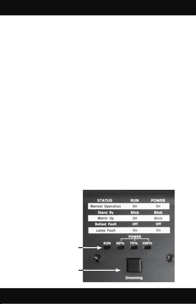
corporate a dimming button with LED indicators to provide for energy
- saving dimmability with both HPS & MH lamps. These instructions
are based on operation of standard HPS & MH lamps. Supply power
is based on typical commercial or residential 120/240V, 60Hz input.
This product must be used with the appropriate wattage recommended
HPS/MH lamps to achieve the highest efciency, safety, luminosity,
and to guarantee proper operation.
Warnings:
This manual contains important safety measures that should be fol-
lowed during the installation and maintenance of the product. Please
read it thoroughly before installing and operating this product.
1. This digital ballast is designed specically for HPS & MH lamp
operation.
2. This ballast is for indoor use only. Avoid exposure to excessive
heat or contact with liquids.
3. This ballast does not rely on the luminance enclosure for protec-
tion against accidental contact with live parts.
4. To ensure proper lamp ignition, the lamp cord should not be
longer than 30 feet.
5. Do not install or otherwise perform any maintenance, lamp
changes, or other modications while the ballast is connected to
the power supply.
6. Please contact the retailer for service if the ballast does not work
after conrming the power connection, output connection, bulb
operation and utilizing the Reset function.
7. Do not try to open the ballast. Opening the ballast will void the
warranty.
2
ALWAYS DISCONNECT POWER BEFORE MOVING
UNIT, CHANGING LAMPS, ETC.

MODEL Main
Voltage
Watts Amps
(Imax)
Amps 100%
Power
Amps 75%
Power
Amps 60%
Power
Power
Factor
Working
Voltage
Ignitor
Voltage
THD CF ta tc
PHE1THD 120/240 1060 9.2/4.6 8.8 - 120v
4.4 - 240v
6.9 - 120v
3.4 - 240v
5.3 - 120v
2.7 - 240v
> 0.98 100-275 4.0 kV < 8% 1.414-
1.6
40℃/
104℉
70℃/
158℉
PHE1TH240 240 1060 4.6 N/A N/A N/A > 0.98 190-275 4.0 kV < 8% 1.414-
1.6
40℃/
104℉
70℃/
158℉
PHE600D 120/240 636 5.5 5.3 - 120v
2.7 - 240v
4.2 - 120v
2.1 - 240v
3.2 - 120v
1.6 - 240v
> 0.98 100-275 4.0 kV < 8% 1.414-
1.6
40℃/
104℉
70℃/
158℉
PHE400 120/240 424 3.7 N/A N/A N/A > 0.98 100-275 4.0 kV < 8% 1.414-
1.6
40℃/
104℉
70℃/
158℉
PHE250 120/240 265 2.3 N/A N/A N/A > 0.98 100-275 4.0 kV < 8% 1.414-
1.6
40℃/
104℉
70℃/
158℉
Performance (see back page for denition of terms)
About your ballast
3
DIMMABLE - DUAL VOLTAGE
PHE1THD & PHE600D
LED status
panel
Reset
Buttons
Input
Receptacle:
120/240v
Reset
Buttons
Input Cord:
240v
Dimming
switch
Output
Output
Output Input
Receptacle:
120/240v
Reset
Buttons
DUAL VOLTAGE
PHE400 & PHE250
NON DIMMABLE - 240V
PHE1TH240

For wall mounting:
1. Install 2 wall screws approximately 4 9/16”
apart (Fig. A). If studs are not available, use
drywall anchors sufcient to hold 15 lbs.
Ensure that screw heads are large enough to not
slip out of slot in handle, but not too large to t
through the large opening on the keyhole slot.
2. Leave screw heads protruding approximately
1/8”-1/4” from wall.
3. For optimum cooling conguration, we
recommend that the ballast be mounted
vertically with the output connector towards the bottom.
Ensure that keyhole slots are oriented correctly (large hole down).
4. Loosen handle screws (Fig. B) and slide handle to center for wall
mounting (Fig. C) then retighten screws.
Installing and connecting the ballast:
1. Find a suitable location for the ballast with sufcient cooling and
away from any heat source. We recommend vertical mounting.
2. Before plugging your ballast in, make sure it is disconnected from the
power source, the lamp is rmly installed into the lamp socket, and
the Lock & Seal lamp cord is securely connected to the ballast.
3. Only use Hydrofarm provided power cables to connect the ballast
to input power.
4. Lamps with auto-ignitors will not work with this ballast. Not for use
with external ignitors.
Fig. A
Fig. B Fig. C
Installation
4
INITIAL START UP: We recommend that you run your ballast
and bulb for at least 12 straight hours after initial start-up. This will
improve lamp life and performance.

NOTE: When operating in a vertical position
(and not mounted on the wall), the handle
must be positioned ush with the bottom of
the unit for maximum support (Fig. F).
Fig. D Fig. E
5. Slide ballast onto screws. (Figs. D & E)
Fig. F (Standing)
The reset buttons work based on input power.
For 120v only one reset will trip if there’s an
issue, for 240v both may trip. The reset buttons
also work as thermal cutoffs, and may trip in case
of an overheating situation. After a reset button
trips, wait 15 minutes before pressing the reset
button. If after resetting the ballast, the problem
continues, please contact your retailer for repair
or replacement instructions.
Resetting the Ballast
Installation (cont.)
5

Phantom Dimmable
The following applies only to Phantom Dimmable models:
Operation:
1. When starting a cool lamp, the ballast will apply 100% power for
15 minutes to properly heat the gasses in the lamp. The dimming
feature will not operate during this initial start-up period, but you
can preset the dimming ratio during this time without impacting
the warm up. After the warm up is complete, the ballast will run at
the set dimming ratio.
2. Press the dimming button to cycle through the dimming levels.
The appropriate LED indicator will light up to indicate selected
dimming level (100%-75%-60%).
3. In the event of an input power failure, check your power
connection, and then reset the ballast per the directions on page 5.
Warning: If the ballast does not work after the reset, please return
it to the place of purchase.
4. Please check the output connection or replace the bulb in the
event of an output failure. If the ballast continues to fault after
precautions are taken, please return it to the place of purchase.
5. The Phantom line of ballasts has built in hot-restrike programming
to protect the lamp and ballast in the event of the ballast turning off
unexpectedly. The ballast will not attempt to restart a hot lamp for at
least 15 minutes. If your lamp fails to start immediately, DO NOT
cycle the power on and off. This can damage the lamp and ballast. If
after 1/2 hour your lamp is still not lit, shut off power to the ballast,
and reconnect. This will begin the startup sequence again.
Dimming switch
alternates ballast
output
LEDs indicate
operation status and
power level setting
6

Main Voltage – Rated input voltage for the ballast
Watts – Input power
Amps – Input current, or draw
Power Factor – A measurement of how effectively the ballast con-
verts electrical current to useful power output, in this case, output
to the lamp. Power factor is measured between 0-1, the closer you
get to 1, the more effective the circuit is said to be. The Phantom’s
power factor is greater than .98.
Working Voltage – The acceptable operating range for input volt-
age to the ballast. Deviations from the rated numbers may result in
decreased ballast performance and additional case generated heat.
Ignitor Voltage – Ballast output during ignition sequence.
THD (Total Harmonic Distortion) – A measurement of all har-
monics present in a circuit. The higher the number, the more stress
is applied to internal parts, the lamp, and the power grid. Gener-
ally, a number below 10% is considered desirable in an electronic
ballast application.
CF (Crest Factor) – A measurement of how “clean” the ballast
power output wave is. A perfectly clean output sine wave would
have a CF of 1.414. Given that some harmonics must exist in
an electrical system, the crest factor must always be higher than
1.414. Therefore, the closer the ballast is to a CF of 1.414, the
easier it is on the lamp.
ta (Ambient Temperature) – Maximum rated ambient tempera-
ture for the ballast area. Excessive ambient temperature can result
in ballast failure, safety shutdown, or lamp failure.
tc (Case Temperature) – Maximum temperature that the case of
the ballast should reach. If the case temperature exceeds this number,
the ballast may be malfunctioning, or the ambient temperature may
exceed the rating.
Definition of Terms
7

5
5
on reflective
materials
Hydrofarm warrants the Phantom Ballast to be free from
defects in materials and workmanship. The warranty term
is 3 years full/2 years prorated beginning on the date of purchase.
Misuse, abuse, or failure to follow instructions are not covered
under this warranty. Hydrofarm will, at our discretion, repair or
replace the ballast covered under this warranty if it is returned to
the original place of purchase. To request warranty service, please
return the ballast, with original sales receipt, to your place of pur-
chase. The purchase date is based on your original sales receipt.
Hydrofarm Inc.
2249 S. McDowell Blvd., Petaluma, CA 94954
www.hydrofarm.com
WARRANTY
3 Years Full/2 Years Prorated
v2-2.2.2010
Other manuals for PHANTOM PHE400
1
This manual suits for next models
4
Table of contents
Other Hydrofarm Electrical Equipment manuals