6 www.hydrofarm.com
instrucciones
Fig. A
Fig. C Fig. B
• FC(Factordecresta): Una medida de la “limpieza” de la onda de salida de potencia del balastro.
Una onda sinusoidal perfectamente limpia de la salida de potencia tendría un FC de 1,414.
Dado que deben exisr algunos armónicos en un sistema eléctrico, el factor de cresta debe ser
siempre superior a 1,414. Por lo tanto, cuánto más cerca está el balastro de un FC de 1,414, más
fácil es la situación en la lámpara.
• ta(temperaturaambiente): Temperatura ambiente nominal máxima para el área del balastro.
Una temperatura ambiente excesiva puede provocar un fallo del balastro, una parada de
seguridad o un fallo en la lámpara.
• te(temperaturadelencapsulado):Temperatura máxima que debe alcanzar el encapsulado del
balastro. Si la temperatura del encapsulado excede este número, el balastro puede funcionar
incorrectamente o la temperatura ambiente puede exceder la temperatura nominal.
INSTALACIÓN Y CONEXIÓN DEL BALASTRO
Paraunfuncionamientoadecuadodelaslámparasnuevas,serecomiendaacvarelbalastrode
Phantomylabombilladurante12horasseguidascomomínimodespuésdelarranqueinicial.Esto
mejorarálavidaúlyelrendimientodelalámpara.
1. Encuentre una ubicación adecuada para el balastro con refrigeración suciente y que esté alejada
de cualquier fuente de calor.
2. Instale rmemente la lámpara en el portalámparas y conecte el cable de la lámpara al balastro.
3. Solobalastrosregulables: Gire el botón regulable hasta el ajuste deseado (60%, 75%, o 100%).
4. Conecte el cable eléctrico al panel de entrada eléctrica en el lateral del balastro.
5. Conecte el cable eléctrico a la fuente de alimentación (toma de corriente).
MONTAJE DEL BALASTRO EN LA PARED
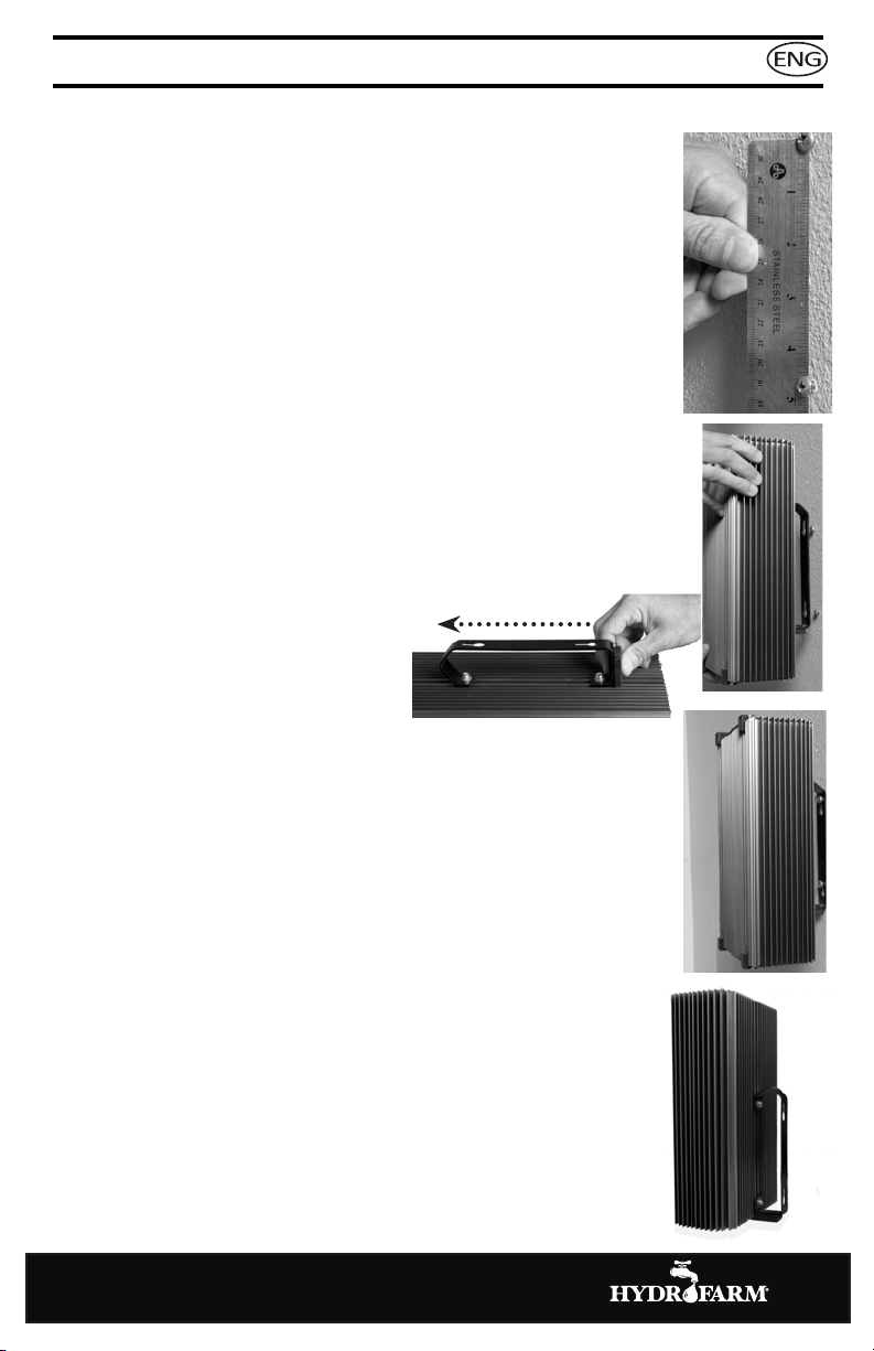
1. Rere las piezas de la bolsa del equipo. El mango del balastro ene los
tornillos y los pernos ya colocados sin apretar en sus oricios. Busque una
ubicación adecuada para el balastro.
2. Instale 2 tornillos de pared separados aproximadamente 11,6 cm. Si no hay
tacos disponibles, ulice anclajes para Pladur que puedan sujetar 6,8 kg.
Asegúrese de que las cabezas de los tornillos sean bastante grandes para no
salirse de la ranura del asa, pero que no sean demasiado grandes como para
no pasar por el oricio grande de la ranura con forma de llave (Fig. A).
3. Deje que las cabezas de los tornillos sobresalgan aproximadamente 0,3 – 0,6
cm de la pared.
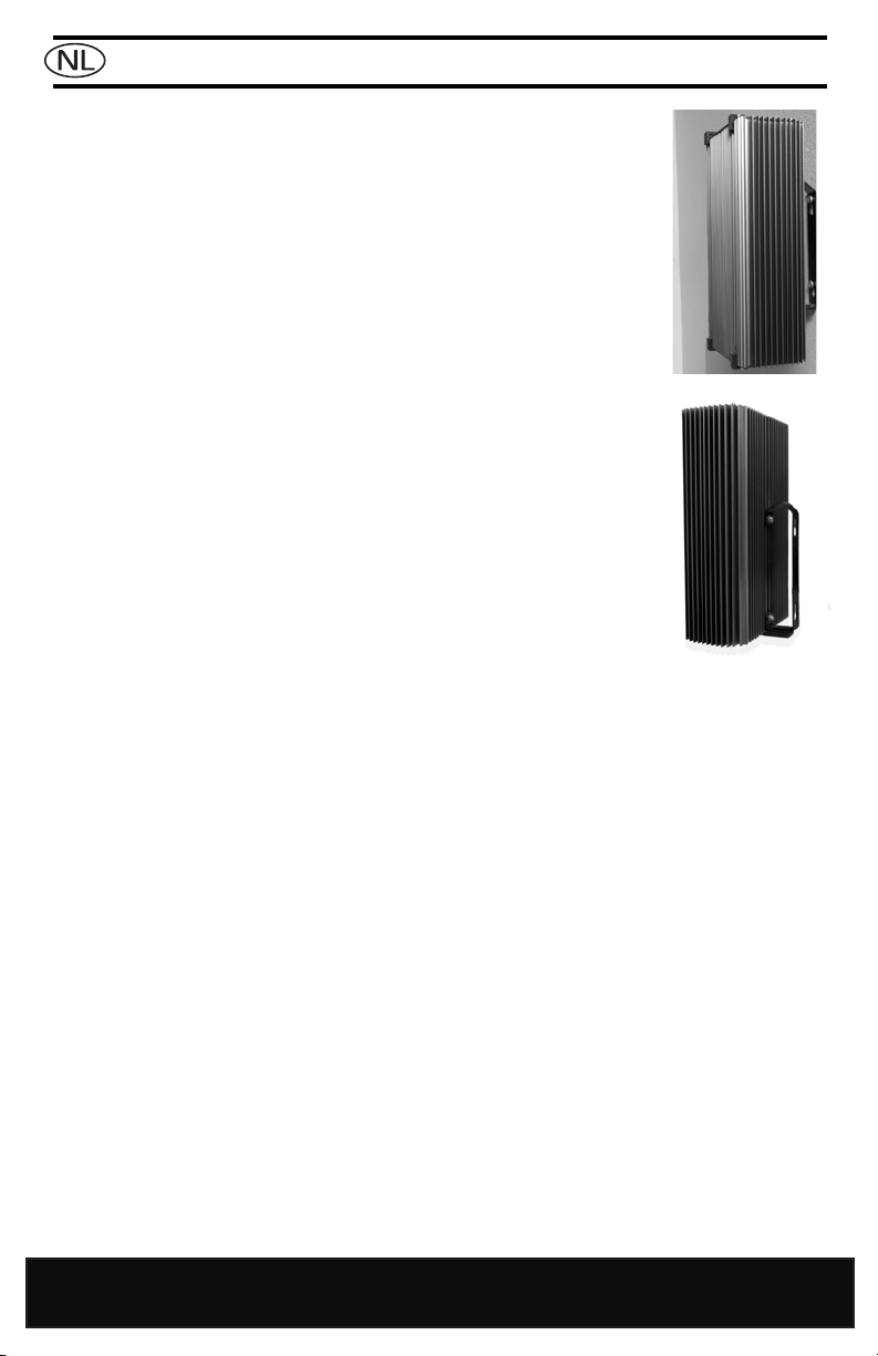
4. Monte el balastro de manera vercal, con el conector de salida hacia la parte
inferior, para una conguración de refrigeración ópma. Asegúrese de que las
ranuras del ojo de la cerradura están orientadas correctamente, ojo grande hacia
abajo (Fig. B).
5. Aoje los tornillos del mango y deslícelo hacia el centro (Fig. C) para el
montaje de pared y después vuelva a
apretar los tornillos.