hydrofuse Fertilizer Machine V1.3 User manual

Installation Manual
Fertilizer Machine V1.3
www.
hydrofuse
.com

Introduction
•Hydrofuse is a new concept in fertilizing that works with existing irrigation (sprinkler)
systems and automatically dispenses fertilizers to all lawns
and gardens.
•Hydrofuse is a quality patented product made exclusively in
the USA. It is designed to provide many years of reliable use
and requires only minimal maintenance.
•The Hydrofuse system will work with virtually any automatic
commercial or residential irrigation system that uses a Timer
(also called “Controller” or “Clock”).
Precautionary Statements
•This system operates on 110 – 120 volts AC, and uses only 60
watts when running. The power supply is UL listed, and all internal voltages are 24 VAC.
However, never touch any wires or electrical parts when the Power is switched on.
•The Hydrofuse system is designed to virtually use any water-soluble fertilizer. Fertilizers
must completely dissolve in the water. Any solids left in the liquid fertilizer supply container
may clog the pump or supply tubing which will void the warranty and may cause
unpredictable results.
•Please be sure to adhere to all Federal, State and local regulations when installing or using
Hydrofuse products.
The following pages show you how to install the Hydrofuse system. Please follow
this guide in sequence for the easiest and most effective installation.
Preparing for the Installation.......................................................................................................................................................................... 1
Planning out the Installation ............................................................................................................................................................. 1......... 1
Performing the Installation ................................................................................................................................................................ 2......... 2
Priming and Testing..........................................................................................................................................................................................10
Winterizing............................................................................................................................................................................................................11
Troubleshooting Guide.....................................................................................................................................................................................12
Warranty................................................................................................................................................................................................................12

1
Preparing for the Installation
What’s in the Box?
In the box there are the following parts, please check that
everything is included. If anything is missing, please call us at
1-281-500-9800.
•1Hydrofuse system
•20 feet injection tube
•1check valve for injection point
•1 ¼” to ½” NPT adaptor
•1 1” Flow Sensor + 20’ Cable
•1key for door
•1 Installation Manual
Back Flow Prevention
Please be sure to adhere to all Federal, State and local
regulations when installing or using
Hydrofuse products. Back Flow valves may be subject to
specific regulations in your area.
Planning out the Installation
When planning out the installation, look at the irrigation system layout from the viewpoint of how it will be
easiest to connect the Hydrofuse system.
Firstly, select the best place to install the Flow Sensor / Injection Point in the irrigation Main Line should be
installed after the sprinkler system backflow device but before the mainline tee’s off to go different directions
and BEFORE the first irrigation valve.
Once this is done, you can then determine the best location for the Hydrofuse machine itself. The Flow Sensor
and Injection Point comes with 20 feet of cable / tubing so ideally mount the machine as close as possible to
the where you will connect to the irrigation main line. The machine needs to be mounted to a wall, and there
should be a 120-volt outlet nearby.
Note: Because the Hydrofuse system uses a Flow Sensor it will work with any number of irrigation zones. It
will sense the actual water flow and precisely inject the correct amount of fertilizer to suit the quantity of
water flowing in each zone.

2
Preparation
Before you leave to do the installation, make sure you have all the equipment needed. Below is a checklist of
what you will usually need. It may be helpful to check each off each thing before you start.
Note: None of the following is supplied with the machine because the parts required vary depending on
the particular installation.
Tools Checklist
1. Toolbox with all common tools.
2. Spade to dig trench (If needed for your installation).
3. Drill with drill bits, hole saws, etc.
Parts Required for Installation
1. 5 gallons fertilizer solution to fill the machine. Note: It will take approx. ½ gallon to prime the machine
before it will start to operate.
2. Four # 12 screws 1 ½” long to mount box to Garage/House (Tap Cons for Concrete, Wood Screws for
Wooden walls, etc.).
3. Silicone sealer to seal mounting screws on machine.
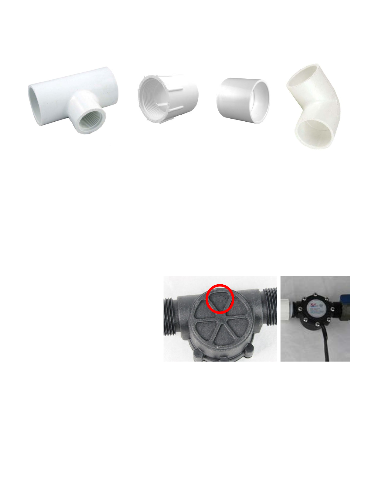
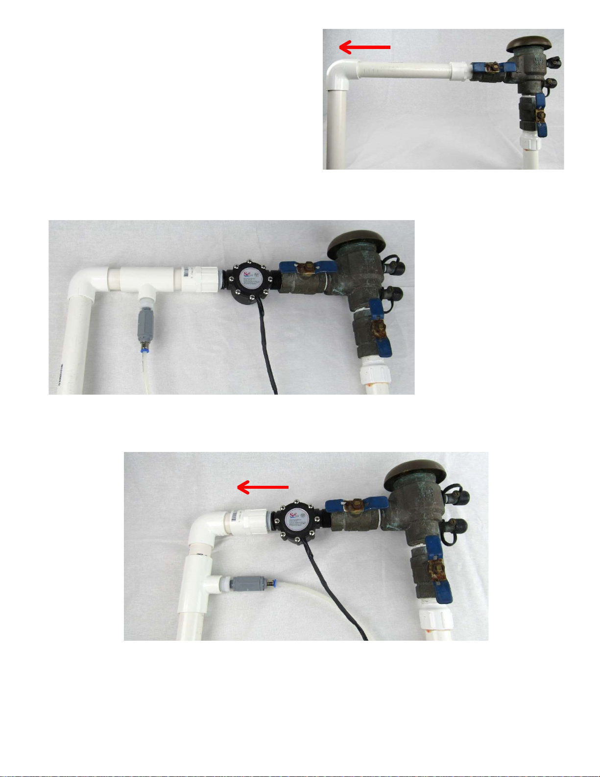
4. Pipe fittings to connect the Flow Sensor and Injection Point into the irrigation system main water pipe
(Included, covered on page 4)
5. Pipe Sealing Compound to seal the pipe fittings for Flow Sensor.
6. Clips to attach tubing to the side of the Garage/House.
7. Optional: ½” conduit to protect tubing if tube is to run in a position where it could be damaged (not
included but available at Home Depot or Lowes).
Performing the Installation
Note: Before you start, it’s a good idea to mentally go through the whole job making sure that you have everything you
need to complete the whole installation process.
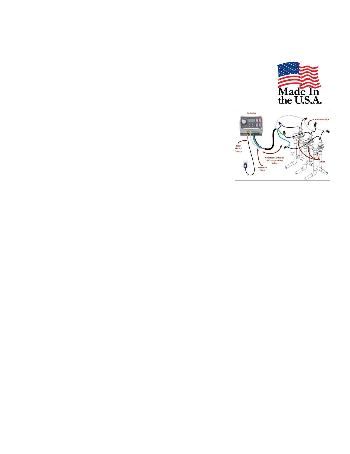
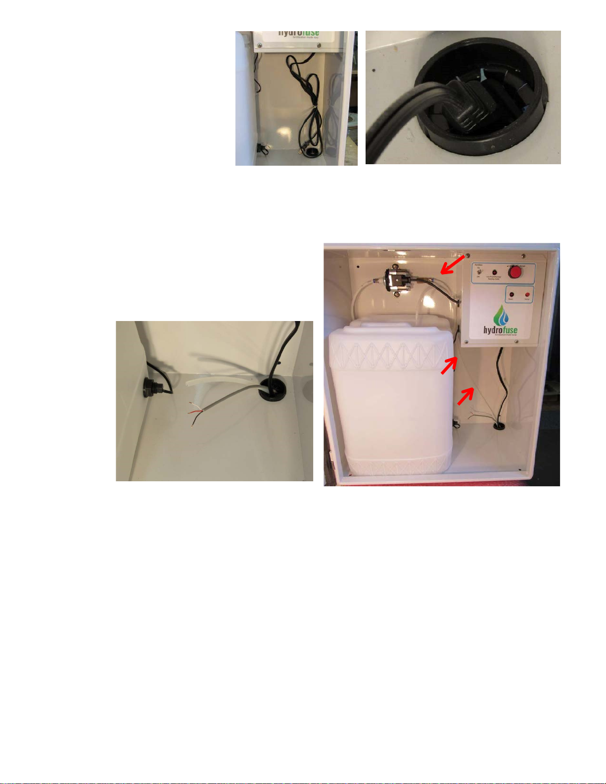
1. Location for the Machine. Pick a good location where you will easily be able to run the injection tubing,
Flow Sensor, and also a 120 V power outlet to plug the system into.
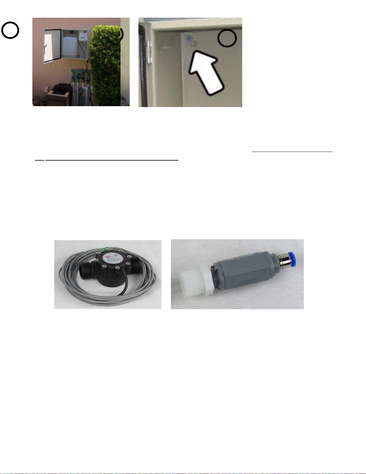
2. Mount to the wall using four 1 ½” long # 12 screws. Use appropriate screws for the material the wall is
made of - wood or masonry. Choose a height that is good for your customer so they can easily operate the
system and use a level to ensure the machine is not at an angle. Tip: If desired the box can be painted to
match the color of a house.
3. Seal the Screws with a small amount of silicone sealer to ensure water does not enter the enclosure.

3
IMPORTANT: Before continuing turn off the water supply to the irrigation system. When done turn the
water back on.
4. Connect the Flow Sensor and Injection Point into the irrigation main line. This must be downstream of
the backflow preventer and before any of the valves. Often the easiest place to inject is right next to the back
flow valve as shown in some of the pictures next page.
IMPORTANT: The Hydrofuse system must be installed with adequate backflow protection to comply with applicable
Federal, State, and Local Codes.
We supply the Flow Sensor and Injection Point and the common PVC fittings used to connect them into your
main line. Customer is responsible to provide PVC fitting needed to tap into the mainline if PVC supplied fitting
will not adequately provide a mainline tap.
Here are the common fittings that you may need to purchase. Fittings are very cheap and easily obtained from
SprinklerWarehouse.com or local hardware store:
2
3
1
Flow Sensor
Injection Point

4
1” to ½” NPT “T” Fitting 1” threaded 1” Coupling to join 1” Bend
mounting Injection Point Coupling to connect irrigation pipe
pipe to Flow Sensor
Irrigation Pipe Sizes
Many irrigation systems use a 1” size main line. The Flow Sensor supplied is 1” for this reason. If your main
line is ¾” / 1” / 1¼” you can use the supplied Flow Sensor. For ¾” and 1 ¼” just use a reducer to plumb in the
Flow Sensor. These are included with the purchase of the machine.
Installing the Parts
The Injection Point and Flow Sensor can be plumbed in a number of ways as long as they are fitted in the main
irrigation line, above ground level and downstream of the Backflow Valve. The Injection Point should be
downstream of the Flow Sensor so that fertilizer doesn’t pass through the Flow Sensor.
The Flow Sensor needs to be installed
correctly. Note the arrow which indicates the
direction of flow. The flow is from the
backflow valve, then through the Flow Sensor,
then through the Injection Point.
The Flow Sensor needs to be installed with
the wires facing down. This is so water cannot
enter the switch.
UP
Wires exit on
bottom Side

5
The pictures below show various ways the Injection Point
and Flow Sensor can be plumbed in. Use these pictures as
a guide to help you determine what configuration is best
for the way your irrigation system is laid out.
Basic installation showing Flow Sensor screwed into Backflow Valve, T Fitting next, and then a bend.
Installation showing Flow Sensor screwed into Backflow Valve, then a bend and the T Fitting installed
after the bend.
FLOW
Common Backflow Prevention Valve
(
before installation)
FLOW

6
Same installation as above but with the addition of a quick disconnect that allows the Flow Sensor to
be removed for cleaning (if necessary) without cutting any pipes.
Installation in a
straight section of
mainline pipe
FLOW

7
Installation in a straight section of mainline pipe but with a pair of quick disconnects to allow the Flow
Sensor and Injection Point to be removed if necessary
When assembling PVC fittings use appropriate cement for the type of irrigation tubing you have. PVC plastic
is the most common but there are other types so check what your system has before buying extra fittings and
cement. Follow instructions on cement bottle to ensure correct joints.
5. Fitting the Injection Point –Apply Teflon tape then screw the reducer into the T fitting you installed in
the irrigation main line. Again, apply Teflon tape then screw the grey Check Valve into the reducer and
tighten with reasonable force. Connect one end of the 20’ length of tubing by pushing it firmly onto the end
of the check valve inside the blue band.

8
6. Route the Electrical Cable – cut the
zip tie holding the electrical cable
and push the plug down through the
grommet at the bottom of the
machine as shown:
7. Run the Injection Pipe and the Flow Sensor to the Hydrofuse unit. It’s best to run them in a piece of ½”
diameter flexible or rigid conduit. This protects them from shovels, weed whackers, etc.
8. Run the Flow Sensor cable - through the hole in the bottom of the electrical enclosure.
Next, run them both through the hole in the bottom of
Hydrofuse unit. From there connect the injection tube to
the right side of the pump. Push the tube firmly into the
pump fitting.

9
9. Removing the Control panel -
firstly remove the control panel and
temporarily re-attach it upside-
down with 2 screws as shown in the
picture below – this will make it easy
to connect the Flow Sensor without
needing a “third hand” to hold the
panel still.
11. Replace Control Panel— the control panel is now ready to be refitted. Replace it and secure with the 4
screws.
12. Connect to the Power—now plug the machine into a
standard 120-volt AC outlet. The system draws a maximum
of 1 amp so any outlet will be suitable.
The red POWER LED should now come on and stay on
permanently.
10
. Connect the Flow Sensor
– to the connector named “J16 FLOW
RATE” as shown in the pictures. Red wire to PWR, White wire to
FLOW & Black wire to GND:

10
The installation is now complete and the machine is ready for filling, priming and testing.
Priming and Testing
When the installation is complete, the following steps need to be taken to set the unit up.
13. Fill the Reservoir – with 5 gallon of soluble fertilizer and water. Refer to fertilizer instructions for how
to mix the product. Only use with fertilizers supplied by Sprinkler Warehouse specifically for this machine
or the warranty will be voided.
14. Priming— to prime temporarily remove the injection pipe from the check valve or the pump will not be
able to prime. Turn the FERTILIZER switch to the ON position, and then press the PRIME button on the
machine until the liquid has passed through the pump and all the way through to the check valve. This will
take 20 – 40 seconds and only needs to be done once. Then fit injection pipe back onto the check valve.
15. Testing—to test the system simply run your irrigation system in its manual mode. This will immediately
start a fertilizer treatment cycle. The LOW FLUID / RUNNING light comes on solid to indicate that the cycle
is running, and as the sprinkler system cycles through each zone the Hydrofuse system will inject fertilizer
into the water stream. When the water flow stops the Hydrofuse system will stop injecting. The LOW FLUID
/ RUNNING light will remain on for 1 minute after the water stops flowing.
BE SURE TO CHECK FOR LEAKS AROUND PUMP AND AT THE INJECTION POINT AND FLOW SENSOR. TIGHTEN
FITTINGS IF ANY LEAKS OCCUR. CALL IF ISSUE PERSISTS.

11
Winterizing
The Hydrofuse system can easily be winterized. To winterize the system follow the steps below:
1.Remove the electrical connectors for the float switch taking care to press the small release lever and only
pull on the plastic connectors (1) – never pull on the wires themselves or they may pull out of the
connectors.
2. Push on the blue ring and remove the pump pick up tube from the reservoir (2).
3.Remove the reservoir from the machine (3).
4.Next turn off the Irrigation system water supply and bleed down pressure in the system by turning on
one of the zones.
5. Now take the pipe that you removed from the reservoir and blow through it with compressed air with at
least 30 PSI (4) to clear the lines and pump of all liquids, which will now be in the irrigation piping.
6. Lastly, blow out the Irrigation system piping as you normally would to winterize the Irrigation system.
7.When you are done store the reservoir in a place not subject to freezing temperatures.
Spring Start Up
When the temperatures are consistently above freezing reverse the above steps, and then prime the system
as described in section (1) of the “Priming, Testing, and Setting the Timer” section above.
2
3
4
1

12
Troubleshooting Guide
Here is a list of common questions, if this does not resolve your issue then please call us.
1. The System does not work at all - Firstly, check that you have a live power outlet. If it’s live, then check
to see if the Power LED is on. If not check the fuse inside the control unit box. If it is blown then call us for
help. The fuse is a common 5-amp automotive type glass fuse. Next, check to see that the LOW FLUID light is
flashing. If so, add more fertilizer until it turns off, and then try the machine again.
2. I Can’t prime the System - Make sure that the injection tube is not connected to the check valve (for
priming), the system will not prime properly if the tube is connected. Also blowing compressed air through
the pump can free a sticky valve which can occur if the machine has been sitting dry for any time. If for any
reason, you cannot get it to prime then please call us.
3. Itdoesn’t inject fertilizer – listen carefully to see if the pump is pulsing periodically. It’s best to do this
test when using Dosage Setting # 4 as the pump will pulse more often on this setting making it easier to test.
If the pump is pulsing then re-prime the system. If the pump is not pulsing then make sure that the Flow
Sensor is fitted the correct way around and that it is wired to the control panel correctly.
If all the above points are okay, please call for further assistance.
Limited Warranty
Hydrofuse warrants to the original purchaser only, that this product is free from defects in workmanship and
materials. This applies for a period of one year after the date of purchase. The warranty is voided if the
customer uses concentrates other than those supplied by Hydrofuse.
What the Limited Warranty Does Not Cover
This limited product warranty does not cover product misuse, improper installation, modification, alteration,
impact, accident, and physical damage that are not the result from any defects in workmanship and materials.
Physical damage of the product voids this limited warranty.
What We Will Do To Correct Problems
Within 30 days of receipt of product and proof of purchase, Hydrofuse will inspect the product to determine
the existence of any defect in workmanship and materials. If Hydrofuse discovers a defect in workmanship
and materials then Hydrofuse will, at our sole option, either replace or repair the product.
How You Can Get Service for a Warranty Claim
A Returned Merchandise Authorization (RMA) number is required for all returns. In order to submit a claim
under this limited product warranty, you must obtain a Returned Merchandise Authorization (RMA) number
from Hydrofuse; provide Hydrofuse with proof of purchase and the product. You are responsible for all
shipping charges and the payment of such charges to return the product to Hydrofuse. You can call for a RMA
number and other warranty claim information.

13
Disclaimers
Implied warranties including that of merchantability and fitness for a particular purpose are expressly
limited to the duration of this limited warranty. Under no circumstances shall we be liable to purchaser or
any other person for any special or consequential damages whether arising out of breach of warranty, breach
of contract, tort, indemnity, contribution, or otherwise. We do not warrant or guarantee that the product is
in compliance with your state’s/province’s ordinances.
There are different regulations in various areas that determine who can install systems such as this one.
Please make sure you adhere to all Federal, State and local regulations in the area that you are installing in.
Also, some areas may require installers to be a licensed Irrigation Professional; others may require a Pest
Control License, for example. Hydrofuse takes no responsibility for advising anyone about what the legal
requirements may be in any specific area or in general. Hydrofuse LLC takes no responsibility for the way its
products are installed or the installer’s adherence to any and all legal requirements.
How State/Province Law Applies to the Limited Warranty and Disclaimer
Some states/provinces do not allow limitations on how long an implied warranty lasts, so the above
limitation may not apply to you. Some states/provinces do not allow the exclusion or limitation of incidental
or consequential damages, so the above limitation or exclusion may not apply to you. You may also have
other rights which vary from state/province to state/province.
Table of contents
Popular Farm Equipment manuals by other brands

Smithco
Smithco Super Star 42-000-E Operator's manual

roost&root
roost&root Backyard Chicken Coop 2 Assembly instructions

Mayer
Mayer 6160 Big Bale Breaker operating instructions

Arrowquip
Arrowquip PORTABLE Q-CATCH 74 Series product manual

Landoll
Landoll Brilllion Till'N Seed BPSB-8 Operator's manual

Akron
Akron EXG 400 X user manual