Hydrolevel Company CycleGard CG450 Series User manual

HOW TO INSTALL
Low maintenance. No moving parts to wear stick or hang up,
as in float devices.
Solid state circuitry. Designed for the highest level of perfor-
mance and reliability.
Automatically shuts off burner, after delay, in a low water
condition to prevent dry firing.
Time delay allows water to feed above the probe to a safe
operating level.
INTERMITTENT LEVEL TEST – periodically monitors settled water
level for added protection of today’s smaller steam boilers.
Loosen the two control cover binding head
screws and remove the cover. Assemble the
chassis to the probe flange and secure with the
screws provided with the probe.
Connect the ring terminal wire lead to the probe
terminal stud and secure with the lock washer
and wing nut provided. With the power removed,
proceed with installation and wiring according to
the instructions on pages 3-4. Upon completion
of wiring replace control cover.
5
4
Low Water Cut-Offs
For Steam Boilers
120 VAC Operating Voltage
Max. Pressure 15 psi
U.S. Patent Nos. 5,739,504 & 6,390,027
CG450 Series
CGT450 Series
126 Bailey Road
North Haven, CT 06473
Phone: (203) 776-0473 • FAX: (203) 764-1711
www.hydrolevel.com
13
1/4"
2
SAFE
WATER
LINE
The probe may be installed in the
boiler above the lowest safe
water level established by the
boiler manufacturer. Most manu-
facturers provide a suitable open-
ing in the side of the boiler.
Allow 1/4" clearance from the probe to any boil-
er surface, tube or baffle. NOTE: Excessive use of
Teflon tape to seal probe piping threads may
insulate the control from boiler ground. This
could result in the control not operating.
WARNING – To prevent electrical shock or equip-
ment damage, power must be off during installa-
tion or servicing of the control. To prevent serious
burns, the boiler should be thoroughly cooled
before installing or servicing control. Only quali-
fied personnel may install or service the control
in accordance with local codes and ordinances.
Read instructions completely before proceeding.

2
INSTALLATION OF
REMOTE MOUNTED MODELS ONLY
A. To secure mounting plate to boiler jacket,* pre-drill two 3/32" pilot holes using the mounting plate as a template. Secure plate
with sheet metal screws provided. Attach control to mounting plate by slipping keyholes in back of chassis over pre-mounted
screws on plate. Tighten screws.
B. Using a wire nut, attach a wire (min 90°C) to the pigtail lead in the control box. Attach the other end to the probe terminal in
the remote probe housing. Attach a second wire between the ground screw on the control chassis and one of the four screws in
the remote probe housing. Note: Wires and wire nuts not provided.
*Or other suitable surface
B
A

3
Wiring
Connect input voltage (120 VAC, 60 HZ) to terminals 1 and 2.
MODEL CG450
Connect terminal 2 to burner circuit neutral. Connect terminal P2 to
burner Circuit in series with other limit controls. Consult boiler
manufacturer instructions for proper terminal connections. Control
should be wired in series with and before other limit controls.
Optional water feeder connection. Connect feeder N to terminal 2.
Connect Feeder H to terminal 1. Connect feeder “FEED” or “W” to
terminal A. For water feeders with 2 leads, connect feeder neutral
to terminal 2 and feeder hot to terminal A.
Note: Use of a solenoid valve or McDonnell & Miller Model 101A
water feeder may cause flooding and is not recommended for use
with this low water cut-off.
Connect “BURNER” terminal on the CycleGard control to the orange
burner wire (120VAC) located under the oil burner transformer.
See page 5 for schematic wiring diagram and additional
SmartCycle description.
FACTORY
INSTALLED
JUMPER.
DO NOT
REMOVE
1 2
BURNER
POWER
SOURCE
120V
AC
+
0
LIMIT
CONTROLS
AP2P112 BURNER
WATER
FEEDER
3 4
OPTIONAL ACTIVATION
WARNING Electrical shock hazard. To prevent electrical shock, death or equipment
damage, disconnect power supply before installing or servicing control.
Install this control in accordance with all local codes and authorities having jurisdiction. Regulations
of these authorities take precedence over the general instructions provided in this manual.

4
MODEL CGT450 (for boilers with tankless coil)
Optional water feeder connection. Connect feeder N to terminal 2.
Connect Feeder H to terminal 1. Connect feeder “FEED” or “W” to
terminal A. For water feeders with 2 leads, connect feeder neutral
to terminal 2 and feeder hot to terminal A.
Note: Use of a solenoid valve or McDonnell & Miller Model 101A
water feeder may cause flooding and is not recommended for use
with this low water cut-off.
1
2
3
Connect “LOW LIMIT” terminals on CycleGard control to the ter-
minals on the tankless aquastat.
4
Connect “THERMOSTAT” terminals on CycleGard control to T-T
terminals on burner primary control.
5
6
Connect “BURNER” terminal on the CycleGard control to the
orange burner wire (120VAC) located under the oil burner trans-
former.
See next page for schematic wiring diagram and additional
SmartCycle description.
Connect input voltage (120 VAC, 60 HZ) to terminals 1 and 2.
Connect terminal 2 to burner circuit neutral. Connect terminal P2
to burner Circuit in series with other limit controls. Consult boiler
manufacturer instructions for proper terminal connections. Control
should be wired in series with and before other limit controls.
OPTIONAL ACTIVATION

5
Burner/SmartCycle Wiring Connection
Model CG450 and CGT450
Diagram shows how the signal is sent to the Cyclegard from the primary control.
See page 4 & 5 for limit and LWCO wiring.
To provide added protection to today’s smaller boilers, the CycleGard low water cut-off is
equipped with an Intermittent Level Test. This important feature adds protection against false
signals that can be caused by foam and volatile water conditions inside the boiler. The
Intermittent Level Test removes power from the burner at preset intervals. During the test, foam
dissipates and the water level stabilizes – allowing CycleGard to monitor the true water level in
the boiler assuring safe and accurate operation.
The last four digits of the CycleGard model
number determine the frequency and duration
of the Intermittent Level Test (ILT) as shown in
the table.
When the optional SmartCycle feature is activated (see wiring instructions on pages 4 & 5), the CycleGard’s test
time sequencing is restarted each time the burner fires. This feature enables a full burner run cycle (10 or 20
minutes, depending on model) prior to the first Intermittent Level Test. On CGT450 models (designed for boilers
equipped with tankless coils), SmartCycle suspends the Intermittent Level Test during a call for domestic hot
water allowing the boiler to deliver its full BTU capacity to the production of hot water.
CycleGard Intermittent
Level Test Feature
Last 4 digits Frequency Duration
of Model No. of ILT of ILT
1090 10 Minutes 90 Seconds
1560 15 Minutes 60 Seconds
2060 20 Minutes 60 Seconds
2090 20 Minutes 90 Seconds

6
Operating Instructions
NOTE: For proper low water cut-off operation, the boiler should be
cleaned at initial installation and periodically thereafter. Refer to the
boiler manufacturer’s instructions for cleaning procedures.
OPERATING TEST PROCEDURE
1. After installation, bring the boiler water to a safe operating level,
turn on power and set the thermostat to call for heat. The amber
LED lamp should be off. The boiler will fire immediately.
2. Slowly lower the boiler water to a point below the probe. The
amber LED lamp on the control will light. The lamp may begin to
flicker with the bouncing water level. Stop draining the boiler
when the lamp glows steadily.
NOTE: The water should not be lowered beyond a visible point in
the gauge glass.
3. The boiler will shut down within 15 seconds.
IF BURNER DOES NOT SHUT DOWN IN LOW WATER
1. Check to see if a foaming condition in the boiler is preventing the
control from accurately detecting the water level. With power to
the system on, and water above the probe level, set the thermo-
stat so there is no call for heat and allow the burner to shut
down. Then, slowly lower the water in the boiler to a point below
the probe. The amber LED lamp should turn on and the relay will
open after a 15 second delay. Once this has occurred, reestablish
a call for heat and the boiler should not fire. Now raise the water
level to an operating level. The amber light should turn off and
the control should reenergize the burner circuit after a 30 second
delay. If the control functions normally during this test, but allows
water to drop below the level of the probe when the test is con-
ducted with the burner on (as described in the Operating Test
Procedure above), the boiler is foaming. The CycleGard provides
protection for foaming boilers (see CycleGard Intermittent Level
Test Feature on page 5). However, to provide optimal steaming
performance, it is still recommended that you clean the boiler in
accordance with the manufacturer's instructions. The foaming
condition is caused by machining oils, elevated mineral content
from make-up water, grease and other contaminants in the boiler
water. Cleaning the boiler will eliminate foaming conditions in the
boiler and provide for optimal steaming performance.
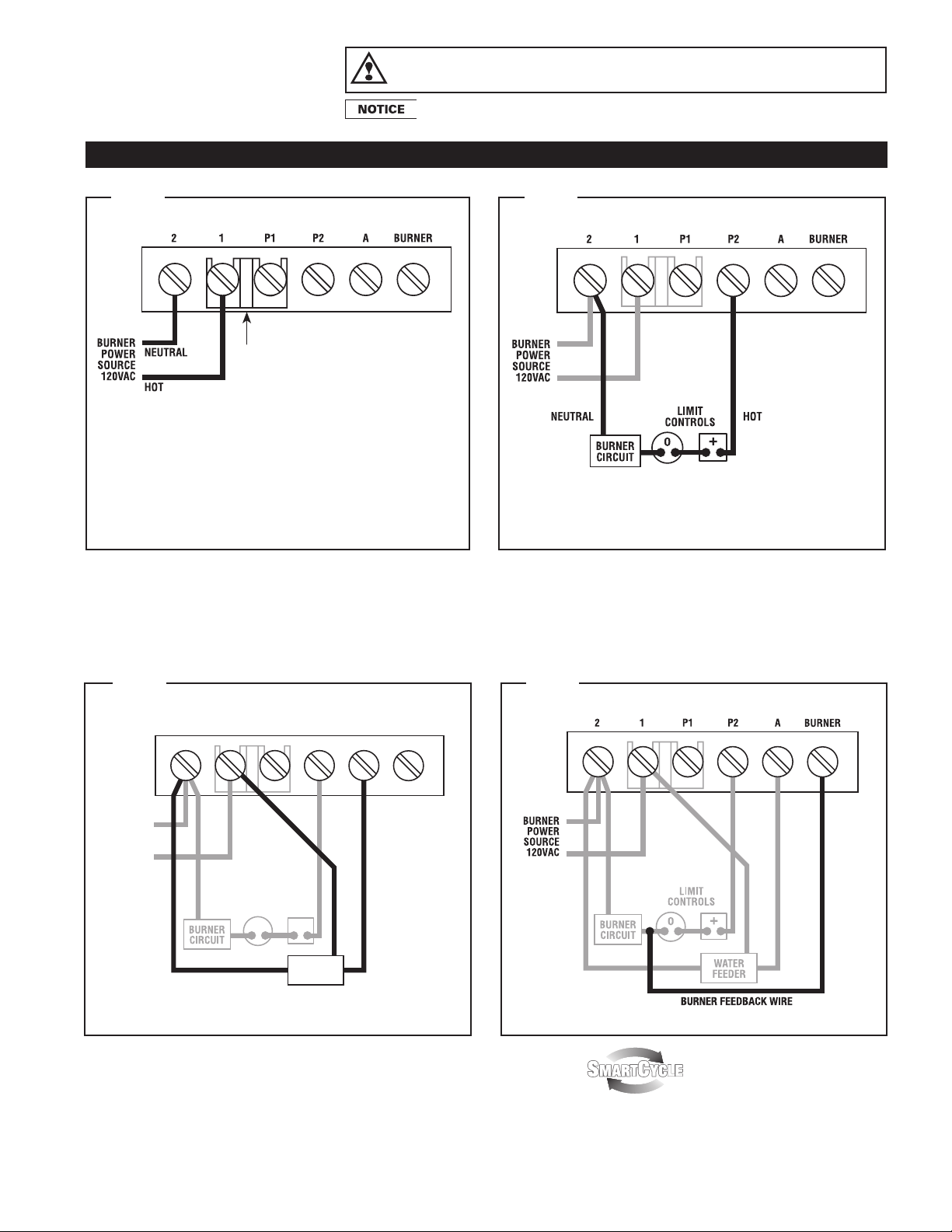
2. Check terminal block wiring to insure that all connections are
correct.
3. Check the probe installation to insure that there is 1/4" clearance
from any surface within the boiler or pipe. (Refer to Step 3 on
page 1 of this instruction sheet.
IF THE AMBER LED LAMP IS ON
The amber LED lamp indicates that the water is below the probe. If
the gauge glass shows that the water is at the correct operating
level and the amber LED is lit check the following:
1. Check for plugged gauge glass.
2. Make sure probe lead wire is properly secured to the terminal.
3. Check for proper ground between probe and boiler shell.
Excessive use of Teflon tape or sealing compound may isolate the
probe from the boiler shell.
4. Remove probe and examine for oily residue. Clean probe with
steel wool and skim boiler.
IF THE GREEN LED LIGHT IS ON
The green LED lamp indicates that the control is conducting an
Intermittent Level Test. The burner does not fire during the test peri-
od. See Intermittent Level Test Feature on page 5 for more details.
Maintenance
To insure optimum performance, remove and inspect the probe
annually.
Clean any sediment or scale from the probe using a scouring pad or
steel wool.
NOTE: Do not use caustic chemicals that could damage the
probe.
Reinstall the probe and perform the Operating Test Procedure
described above.

7
Probes
Test Pressure: 1000 PSI, All Models
The Probe Makes the Difference
The probe used in all Hydrolevel controls offers you dis-
tinctive advantages. Unlike float devices, there are no
moving parts to wear stick, or “hang-up” the in harsh
boiler environment .
A stuck or “hung-up” float can cause dangerous low
water conditions. And if suddenly released, a float can
feed cold water into overheated tubes or plates and
cause explosive results.
The Hydrolevel control has no float bowl so sediment
cannot collect. The reliable solid state circuitry and low
maintenance probe are designed to provide years of
troublefree operation.
EL1214 – STANDARD MODEL – 3/4" NPT
For 1/2", order Model No. EL-1220
EL1214-P – 3/4" NPT
2"
SQUARE
17
/8"
313/16"
15/16"
1"
3/4" NPT
5/16"
2"
SQUARE
17
/8"
49/16"
1"
3/4" NPT
5/16"
111/16"
EL1214-R
REMOTE PROBE
VXT Water Feeder
The VXT Water Feeder (available separately) can be installed with
Hydrolevel or other low water cut-offs to automatically replenish boiler
water in the event of a low water condition. The VXT offers programmable
feed amount and feed delay settings. These can easily be set to ensure the
proper feed amount and to provide adequate time for condensate to return
to the boiler before starting a feed cycle. The VXT Feeder’s Digital Feed
Counter tracks the amount of water added to the boiler exposing system
leaks, which can significantly shorten the life of a cast iron boiler.
Additional features including a manual feed button, underfeed and flood
protection make the VXT an ideal choice for safety and convenience.

8
LIMITED MANUFACTURER’S WARRANTY
We warrant products manufactured by Hydrolevel Company to be free from defects in material and workmanship for a period of two years
from the date of manufacture or one year from the date of installation, whichever occurs first. In the event of any claim under this warranty or
otherwise with respect to our products which is made within such period, we will, at our option, repair or replace such products or refund the
purchase price paid to us by you for such products. In no event shall Hydrolevel Company be liable for any other loss or damage, whether
direct, indirect, incidental or consequential. This warranty is your EXCLUSIVE remedy and shall be IN PLACE OF any other warranty or guaran-
tee, express or implied, including, without limitation, any warranty of MERCHANTABILITY or fitness for a particular purpose. This warranty may
not be assigned or transferred and any unauthorized transfer or assignment thereof shall be void and of no force or effect.
126 Bailey Road • North Haven, CT 06473
Phone: (203) 776-0473 • FAX: (203) 764-1711
www.hydrolevel.com
012422
MAXIMUM PRESSURE: 15 PSI
INPUT VOLTAGE: 120 VAC, 60 HZ
SWITCH RATINGS: 5.8 FLA, 34.8 LRA
SWITCH CONTACTS: SPDT
ALARM CIRCUIT: 125 VA @ 120 VAC Pilot Duty
225/32
37
/8
15
/8
11
/8
15
/8
23
/8
BOTTOM
59
/16
51
/2
1.00
BACK
11
/8
23
/8
15
/8
TOP
Dimensions
Specifications
WARNING Frozen pipes/water damage. Central heating systems are prone to shut down as a result of power or fuel
outages, safety related fault conditions or equipment failure. Installation of freeze protection monitoring or
other precautions is recommended for unattended dwellings in climates subject to sustained below-freezing temperatures.
This manual suits for next models
2
Table of contents
Other Hydrolevel Company Control Unit manuals
Popular Control Unit manuals by other brands

Align
Align 3GX V2.1 Setup

Telit Wireless Solutions
Telit Wireless Solutions LE910C1-NA Hardware user's guide

Chattanooga
Chattanooga Intelect Advanced 2766 user manual

ABB
ABB MRP31.0 manual

Asco
Asco 8030 Series Installation & maintenance instructions

oventrop
oventrop Multiblock T Installation and operating instructions for the specialised installer