manuals.online logo
Brands
  1. Home
  2. •
  3. Brands
  4. •
  5. HydroPoint
  6. •
  7. Controllers
  8. •
  9. HydroPoint WeatherTRAK ET Pro3 User manual

HydroPoint WeatherTRAK ET Pro3 User manual

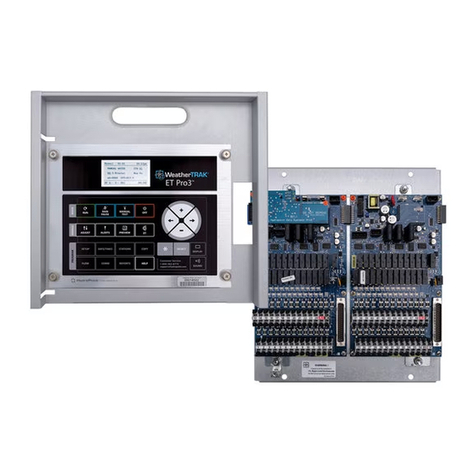
Controller Bidding Specifications
1
1.0 WeatherTRAK ET Pro3 Series Controller Information
1.1 Controller Application
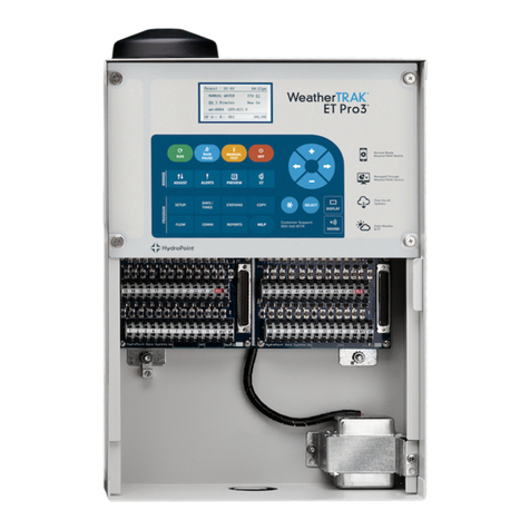
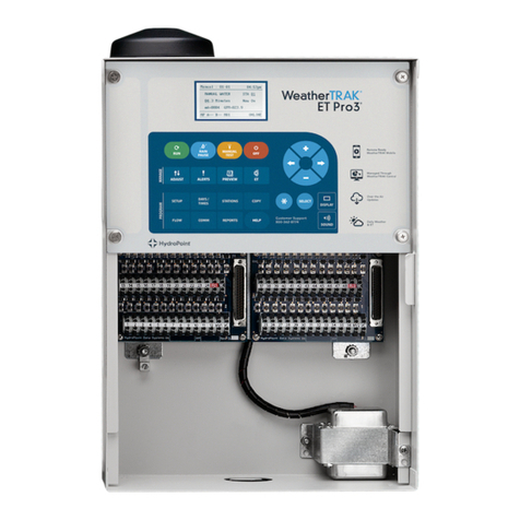
The WeatherTRAK ET Pro3 series controller is designed for commercial, institutional and municipal
applications where water conservation and optimum plant health is paramount. The controller is
suitable for both indoor and outdoor installation and is available in different material finishes in wall
mount or pedestal style enclosure configurations. Pre-assembled chassis models are also available in
various sizes to retrofit into existing irrigation controllers when needed.
The WeatherTRAK ET Pro3 series is compatible with WeatherTRAK Central Internet Management
Services (WeatherTRAK Central) , as provided by HydroPoint Data Systems, Inc., Petaluma, CA.
1.2 Controller Warranty
The WeatherTRAK ET Pro3 series has a five (5) year limited warranty for parts and labor. The optional
pedestal has a five (5) year limited warranty for parts and labor.
1.3 Controller Communication
The WeatherTRAK ET Pro3 series is specified with built-in Central Communication (two-way cellular
wireless modem). Central (two-way) communication provides Central Internet Management with
remote programming; monitoring and real-time notification of field alerts anywhere Internet access
(through a secure login and password) can be obtained.
1.4 WeatherTRAK Central Internet Management Service (WeatherTRAK Central) Features
WeatherTRAK ET Pro3 series controller and services will be provided by HydroPoint Data Systems,
Inc.
The WeatherTRAK ET Pro3 series controller receives local ET updates on a daily basis. Each
controller is assigned an ET Microzone representing approximately 1sq. Km that is associated with
the controller’s exact longitude and latitude coordinates Weather data collected from over 40,000
government-regulated and privately owned weather stations across the U.S. is combined with local
wind, temperature, solar radiation and humidity variables to model an virtual on-site weather station
with the expense of purchasing a weather station, proper sighting and on-going upkeep of
instrumentation.
The WeatherTRAK ET Pro3 controller has the ability to incorporate daily ET Everywhere updates in
two of the three station modes: 1) Auto mode with ET via depletion using crop coefficients (Kc) and 2)
User mode w/ ET by setting reference ET and percent adjustments on a station-by-station basis,
(User No ET does not incorporate ET Everywhere updates).
The WeatherTRAK ET Pro3 downloads the daily ET value and modifies each station’s runtime, water
days, cycle and soak times in combination with each stations calculated depletion value. When user-
defined water days are selected using Automated by WeatherTRAK station mode, the controller will
automatically decide whether to irrigate or not irrigate based on the current day’s ET and depletion of
each station independent of one another. The daily ET updates can be observed under the controller’s
ET Menu as well as the impact of the last delivered ET observed up to 8 weeks ahead under the
Preview Menu function.
It is the combination of the controller’s internal scheduling engine and daily ET updates that have
demonstrated proven water savings, optimum plant health and runoff reduction (caused by over-
irrigation) in multi-year independent studies. The WeatherTRAK Scheduling Engine incorporates the
Irrigation Association’s recognized methodology for irrigation listed in Best Management Practices
(BMP’s) as the methodology for calculating station run times.
Controller Bidding Specifications
2
If an ET value is not received, the controller will continue to irrigate based on the last downloaded
value. When an ET value is not received after five days, the controller will emit a beeping tone every
30 seconds signaling a Communication Alert. Communication can be easily restored by calling
WeatherTRAK’s Customer Service toll-free at 800.362.8774. In the event that ET service has expired
and is not renewed, the controller will continue to beep daily until controller is programmed in User No
ET mode.
WeatherTRAK Central is a yearly subscription based service can be provided upon controller service
activation and additional renewable service subscriptions are available in single or multi-year
increments which includes
•Daily, local ET transmitted wirelessly to controller,
•ET On or Off by station,
•Daily and average weekly ET display,
•Access to HydroPoint’s, toll-free, bilingual customer technical support and for Central
communication users:
oFull remote programming, monitoring, alert and remote alert notification capability
oCIM (Central Internet Management) to manage irrigation schedules for a single or multiple
sites.
2.0 WeatherTRAK ET Pro3 Series Features
2.1 Standard Controller Features
WeatherTRAK ET Pro3 series features are:
•Station counts from 12 - 96 stations.
•Indoor/outdoor wall mount installation or optional pedestal style with key-locking enclosure in
two different finishes and thickness of material based on vandalism potential.
•Eight programs with seven independent water day patterns and schedules. Each program has
two start times with up to 72 cycles, with one water window per program. A second start time is
available for High ET requirements in “Auto mode” only.
•Proven water savings and runoff reduction in more than 25 independent, multi-year studies
including a 100% pass rate of the Irrigation Association’s (IA) Smart Water Application
Technology™ performance test (SWAT™ Test).
•WeatherTRAK ET Pro3 is EPA WaterSense Approved.
•Built-in sprinkler, soil, slope, plant other databases noted as;
o14 different sprinkler types including drip emitters
oDefault or user-defined precipitation rate based on each sprinkler type
oDefault or user-defined sprinkler efficiencies based on each sprinkler type
o17 different plant types
oDefault or user-defined root depths from 2-36” in 1” increments
oDefault or three, user-defined crop coefficients (Kc) for custom plants and native grasses
on a monthly basis
o5 soil types based on USDA soil texture classifications
o4 micro-climates (sun exposure levels)
o5 slope gradients
o4 locations of sprinklers based on slope gradient
o2 Usable Rainfall settings (None or 100%)
oChoice of whether or not to irrigate each specific station within a specified water window
•Skip Days – Automatically skips irrigation days and carries over required irrigation to the
following water day when water windows are exceeded.
•Exclusive WeatherTRAK High ET, user-defined second start-time when soil moisture depletion
in one day is greater than irrigation system can apply in one schedule—all done automatically.
•Independent station watering and watering day adjustment from -50% to +25% in 5%
increments.
Controller Bidding Specifications
3
•Compatibility with normally-closed, wired or wireless rain or rain/freeze switches.
•Compatibility with WeatherTRAK FlowLink, WeatherTRAK FlowShare, WeatherTRAK Flow3
Hydrometer, WeatherTRAK Flow HD, Data Industrial IR-220 Series and Creative Flow Sensor
Technologies (CST), and Netafim Flow Sensors.
•Compatibility with normally open or normally closed master valves, (maximum allowable in-rush
current shall not exceed 1000mA for master valve output).
•Continuous flow monitoring and alert notification at the individual station and mainline level.
•Preview mode that displays flow data and irrigation schedules for each station.
•Reports menu provides accumulated totals of flow usage and station run time on a daily, weekly
and monthly basis.
•Sixteen different types of alert functions act as true water management tools.
•Colored-coded LED’s correspond to station outputs, master valve input, including delivery of 24
VAC on the station input / output board as a standard feature. These LED’s can be used for
faster troubleshooting and diagnosing field issues.
•365-day calendar scheduling.
•User-defined start times and water window from 1-24 hours by program.
•Valve wire diagnostic circuit that identify field wiring issues such as valve shorts or valve no-
connects.
•Selectable Stack or Overlap scheduling modes.
•In Overlap mode, up to four independent programs, a master valve, pump start and station
operating manually can be operated at one time.
•Dedicated master valve terminal output for either normally open or closed models including a
blue-colored LED that illuminates when in use.
•A pump start can be assigned to any single station output and pump start exclusion can be
assigned to one or a maximum of three of the four programs.
•Heavy duty transformer for simultaneous operation of multiple programs inclusive of a master
valve, pump start and manual operation.
•Seven independent water day modes:
oOptimized by WeatherTRAK (ET)
oOdd*
oEven*
oInterval, 1-30 Days
oDays of Week, a 7-day irrigation pattern that is used all year round
oDays of Week By Month, twelve month, 7-day irrigation patterns, for each month of the
year
oOff
* Automated skip days within selected water days based on actual water requirements. When
two consecutive odd days occur, the controller will irrigate on the second odd day.
•5-line, 24 character display with easy-to-follow programming.
•Selectable Rain Pause from 1-200 days.
•Central communication (two-way) Central Internet Management (CIM) provides wireless
communication to the WeatherTRAK Central web link at www.weathertrak.net.Accessed
through a secure login and password issued by HydroPoint Customer Support.
•Water budgeting functionality provides management of allocation against actual usage on a
daily or date range basis.
•Daily ET updated irrigation schedules with an 8-week go-forward schedule for observing
schedules for low-water use or other deep rooted plant material.
2.2 Diagnostics and Alerts Detection Capabilities
WeatherTRAK ET Pro3 shall have:
•Sixteen different alert functions inclusive of:
oContinuous flow monitoring capabilities:
Controller Bidding Specifications
4
!Mainline Break
!Mainline Leak
!Individual Station High Flow
!No-flow
!Leak Detection
!Extended Leak Detection (for systems w/ normally-open master valves)
oValve conditions:
!Valve Shorts
!Valve Over-current
!Valve No-connects (open circuit)
!System Over-current
oCommunication:
!Number of days since last ET update
!Lost communication between the controller and web application server
oWater Window conflicts:
!Water windows exceed Odd/Even day requirements or other site parameters
oWater Day conflicts:
!Insufficient number of irrigation days to meet ET requirements
oHardware conflicts:
!Continual confirmation of terminal board operation
oWeatherTRAK Central service subscription:
!Notification of pending renewal of WeatherTRAK Central Service
Continuous controller monitoring, alert notification and response functions are resident within the
controller and are then transmitted to the web application in real-time for Central communication users
only. WeatherTRAK ET Pro3 models offer the user the ability to receive any of the above stated
alerts based on user selected parameters such as:
•Your specific time zone to receive alerts
•Periods within a 24-hour day to receive alerts
•Several different choices of days of week to receive alerts
•Type of alerts to be received remotely
•Alert notification by email and/or text message to a cell phone
•Exclude controllers within your account from remote alert notification
•Suspension (for an indefinite period of time) and/or reallocation of alert notification to another
individual based on user preferences.
These alerts can be cleared via the controller interface with the exception of Communication and
WeatherTRAK Central subscription Alerts which can be resolved by calling WeatherTRAK’s Customer
Service at 800.362.8774. Water Window and Water Day conflicts are resolved when programming
changes are made.
2.3 Flow Monitoring Capabilities
The WeatherTRAK ET Pro3 controller will be capable of individual station flow sensing and alert
notification from up to four flow meter inputs and four master valve outputs as a standard feature. Flow
requirements are as follows:
•Directly compatible with WeatherTRAK Flow3 Hydrometer, WeatherTRAK FlowHD, and any
one of the following Data Industrial® IR-220 Series Flow Sensors:
o1", 1.25", 1.50", 2.0", 3", 4" and “Insert-Type” flow sensors
•Also directly compatible with any Creative Flow Sensor Technology (CST) flow sensor in
available sizes.
•Also directly compatible with Netafim Flow Sensors.
•Preloaded K and Offset values that correspond with the size of the flow sensor installed
oUser may adjust either value as needed
•Adjustable K and Offset values for special adaptations or “Insert-Type” models.
Controller Bidding Specifications
5
•The signal wire from the flow meter to the controller can be connected directly to a dedicated
flow input terminal and pulses can be read directly from the flow meter without any intermediate
devices.
•User defined flow monitoring thresholds for the following flow monitoring functions (including
“Off” for each function independent of one another (software version 7.6 or higher)
oMainline Break
oStation High Flow
oStation Low Flow
oNo Flow
oLeak Detection
oExtended Leak Detection for mainlines that incorporate normally open master valves.
•Selectable monitoring delay time from 1 to 6 minutes in 1-minute increments for each flow
condition independent of one another.
•User-defined “excluded stations” from “No-flow” monitoring if some flow values are lower than
the recommended flow rates of the flow meter installed.
•Mainline break, Station high flow, low flow and no-flow and leak detection thresholds are user-
defined from 0-995 GPM. Thresholds can be set in 1-GPM increments from 1-30 GPM and 5-
GPM increments from 30-995 GPM.
•The controller can be programmed to operate each station manually for a user defined period
from 1-10 minutes in 1-minute increments (default being 3 minutes) for the purposes of
learning, storing each individual stations flow rate. This flow rate will be compared against a
flow rate each time scheduled irrigation occurs. The user may apply a global Offset value in a
percentage for the station high flow threshold for a single, multiple or all stations from 5-80% in
5%-increments. The user may also override this global percentage and enter their own value in
GPM increments for a single, multiple or all stations from 1-999 GPM in 1-GPM increments.
•The individual station’s learned flow identified as “Assigned Station Flow” (ASF), can be re-
learned at any time or overridden by a user if thought to be incorrect. The user defined value
can be reset back to the default or last learned flow value through a button press in the
appropriate submenu.
•WeatherTRAK ET Pro3 can monitor for mainline break conditions for a single station or multiple
stations operating simultaneously during scheduled and non-scheduled irrigation in either Stack
or Overlap modes. The depletion model will continue to monitor those remaining stations that
did not irrigate and will water these stations on the next scheduled active day and start time.
oA mainline break threshold alert is triggered when one or more stations (Stack vs. Overlap)
flow values exceed the user-defined mainline break threshold. Any operating stations are
immediately stopped after the flow threshold and delay period are exceeded. The controller
continues to monitor for any flow exceeding the user defined threshold with the master valve
open and if flows are monitored, the master valve is closed and all scheduled irrigation is
stopped and a mainline break alert is immediately posted. If the threshold value is not
exceeded, the controller will irrigate the next station(s) in the programming sequence and
note the amount of irrigation remaining for the triggered station(s) as part of the depletion
model. The user can define the delay time in which flow detection will begin for systems
where long laterals or valve locations require flows to “hydraulically balance” before
monitoring takes place. A mainline break alert will be automatically cleared at the next
scheduled start time. If the mainline break threshold and delay period is exceeded the
controller will once again stop all scheduled irrigation and re-post a mainline break alert.
oA Station Low Flow alert is triggered when the global station low flow offset has been
exceeded. The controller will immediately stop all operating stations and monitor for any low
flows. If low flow is measured and exceeds the mainline low flow threshold see expected
controller behavior above. If no flow is measured, the controller will post a station low flow
alert for the stations that operated and move to the next station(s) in the program sequence.
The individual stations with the low flow alert will be posted on both the controller and web
software.
oA Station High Flow alert is triggered with the global offset value or if the user defined
Station High Flow threshold and delay have been exceeded. The controller will immediately
Controller Bidding Specifications
6
stop all operating stations and monitor for any high flows. If flow is measured and exceeds
the mainline break threshold see expected controller behavior above. If no flow is measured,
the controller will post a station high flow alert for the stations that operated and move to the
next station(s) in the program sequence. The individual stations with the high flow alert will
be posted on both the controller and web software.
oA No Flow alert is triggered when a station is scheduled to operate and the No Flow
threshold value and delay periods are exceeded.This may be a result of a pump station
failing to start, a closed isolation valve in the mainline, a closed remote control valve or shut-
off backflow preventer. The controller will immediately post a No Flow alert for the
corresponding station(s) and move to the next station(s) in the program sequence. If three
or more successive stations are flagged as No-Flow, the controller will suspend remaining
irrigation and also immediately post a No-Flow alert to the controller and to the web
application.
oContinuous monitoring for leaks during non-scheduled irrigation or during soak periods
when no other scheduled irrigation is operating. When the user-defined threshold value and
delay period is exceeded, an alert notification is posted on the controller and the web
application, but the master valve is not closed until the high flow threshold is exceeded.
Scheduled irrigation continues and the leak notification will continue to appear until the leak
is repaired or until the threshold value is increased or leak detection is turned “Off”.
oExtended Leak offers an additional time delay for irrigations systems utilizing normally open
master valves. When leak detection threshold and extended leak delay period is exceeded,
the controller will immediately close a normally open master valve, post a Leak Alert and
suspend all scheduled irrigation unless a station is operated manually or until the next
scheduled start time. If the leak stops before the delay period expires, the controller will
reset and continue to watch for leak detection. If the leak appears again exceeded the leak
detect threshold and delay period a new leak detect alert will be posted.
2.4 Optional Controller Features
The WeatherTRAK ET Pro3 offers the following:
•Flow monitoring capability when used with a Data Industrial IR-220 Series, Creative Flow
Sensor Technologies (CST) and Netafim Flow Sensing products.
•Compatibility with normally-closed rain, wind, freeze sensors capable of overriding all scheduled
programming functions when activated. Compatible with Toro, Irritrol and Hunter models.
•Compatibility with normally open or normally closed master valves with or without a flow meter
that is user-defined in the Setup menu. The maximum allowable holding current of compatible
master valves is 1000 mA to avoid station over-current valve alerts.
•A pump start can be assign to any available station output when needed. This assignment can
be done outside of Max Active stations and once it’s assigned, it will no longer have any station
programming attributes.
•A single or up to three programs can be excluded from a pump start when not required. Any
station assigned to a program excluded from a pump start will operate without a pump being
actuated from the controller. This feature will only function for pump starts that are electrically
actuated from a controller not mechanically actuated such as a pressure or flow switch.
•The WeatherTRAK ET Pro3 series has direct compatibility with RainMasterTM Pro-Max UA
Series when used with an EX32 cable assembly (purchased separately) and TRCTM
“Commander” or “Sidekick” handheld remotes by simply connecting to a 32-pin connector as a
standard feature to each 24-station input / output board.
oControllers incorporating pump starts will require the station assigned as a pump start to
be operated manually from the controller as part of using a hand-held remote.
oControllers incorporating normally closed master valves can be operated from either
compatible hand-held remote or by selecting a user-defined time length using the
“Maintenance Timeout “feature found in the MANUAL menu on the controller.
•An optional AC input surge protection kit can be ordered for locations where incidences of
lightning strikes or dirty power are high.
Controller Bidding Specifications
7
•In applications where Central communication phase integrity is low, two accessory kits of
Central antenna amplifier and pole-mounted antennas can be ordered. The communication
type being used will determine if an additional enclosure and other non-supplied requirements
(mast antenna, footing support etc.) are required.
•For applications where station count above 24 stations is required an additional 24-station
input/output board and corresponding stations keys can also be ordered as separate items.
3.0 WeatherTRAK ET Pro3 Programming
3.1 Central Internet Management Capabilities
For Central communication, access to www.weathertrak.net WeatherTRAK Central functionality is
available through a secure login and password. Each user can be assigned their own individual log-in
and password including specific access to a single or multiple controllers in an account. Access to
controllers is determined on a user by user basis and can be revised by HydroPoint Customer Service
toll-free or via an email request at [email protected]. WeatherTRAK Central provides all of
the benefits of a dedicated centrally based irrigation system without dedicated computer hardware or
software. Access to a single controller or multiple controllers can be obtained wherever access to the
internet can be obtained. Other features include:
•A dashboard overview of any “Major Issues” for any controller within an account from the
Home page
•Improved usability with fast and simple page navigation through the use of quick links, key
words, mouse roll-up and right click functions or header links within the web software
•Contextual page HELP pop-ups to for key controller functions such as alerts. This includes:
oSeverity of an alert
oDefinition of an alert
oPossible cause of an alert
oPossible remedies of an alert
oController behavior for each individual alert
oHow to clear the alert once the field or programming issue is resolved.
•Current controller status overview single, multiple or all controllers in rain pause for a single or
multiple days, including setting different day lengths for one or more controllers.
•Change a controllers name up to 50 characters in length
•Preview of each controller’s programming information based on last received ET including the
ability to assign stations to another program or % Adjust a single or multiple stations on the
same page.
•Remote controller setup and programming for a single or multiple controllers within an account
from a single page. Make a single programming change to one or more stations with three
mouse clicks.
•Remote controller setup or programming includes but is not limited to the following:
oAll controller setup functions except for time of day, day of the month and year.
oProgram assignment with a start time, water window and water day mode including any
exclusion day (for auto mode only).
oFlow sensor setup including:
•Flow sensor size
•Flow sensor K and Offset values
•Excluded stations from no flow monitoring
•Station level alert exclusion – High Flow, Low Flow, No Flow
•Multi-vendor flow sensor and master valve database
•Selection of one or more flow monitoring functions GPM threshold values or delay
periods (including “Off”) for
•Mainline Break
•Station High Flow
•No Flow
Controller Bidding Specifications
8
•Leak Detection and
•Extended Leak Detection
•View controller history in the form of the following reports within any user defined period up to
the last 3 years;
oAlert History, defined by current alerts (alerts that have not been cleared) or Alerts log
(Alerts that have been cleared)
oCurrent Controller program settings
oFlow reports for any controller with a flow meter or multiple controllers sharing a single
flow meter
oDaily ET and Station runtime reports
•Reports can be exported into a PDF or Excel file format for additional manipulation as needed.
Reports can be generated for an individual controller, a group or controllers or all controllers
as needed.
•Manual operate a single or group of stations remotely for a single or multiple controllers at the
same time. Manual operation of valves starts immediately and can be stopped at any time.
•Setup and monitor water use for a single or multiple controllers if a known water allocation has
been budgeted against actual usage when a flow sensor is in place. Select monitoring flow
values in:
oKGallons
oGallons or
oHCF or CCF
•Water Budgeting will provide remaining usage in a flow value (selected) as well as remaining
or overuse in percent.
•View current controller alerts along with contextual page help that provides the following pop-
up message with a mouse roll-over and right click;
oSeverity of alert
oDefinition of the alert
oPossible cause of the alert
oPossible remedies to the alert
oController behavior for each alert and
oHow to clear the alert
•Configurable Flow Alarms – Alarm and action, alarm only, off
•Setup individual user Alert Notification Preferences inclusive of any one of the following 16
alert messages be received via email and/or text messages via cell phone;
oTime of day of when messages are to be received,
oDays of weeks
oTime zone
oExclude specific controller for all or some message alerts within your account
oSuspension of all alert messaging for an indefinite period of time or re-assignment to
another individuals email or cell phone as needed.
4.0 WeatherTRAK ET Pro3 Hardware / Electrical Requirements
4.1 WeatherTRAK ET Pro3 Hardware Features
WeatherTRAK ET Pro3 series will have:
•Dual-voltage transformer for usage in either 120V or 220V, single phase AC applications.
•Large power supply for multiple program operation for grow-in periods.
•Interchangeable transformer mounting to for improved usability to accommodate AC power
input from different directions.
•Two different colored LED’s to verify delivery of AC and DC power to key components on the
station input/output board for faster field troubleshooting.
Controller Bidding Specifications
9
•Large screw-less terminal blocks that can accommodate field wire in size from 12-22 gauge
including two inputs per station.
oTerminal blocks on one horizontal plane make field changes a snap, including retrofit
applications.
oAccessible interior space for field wires, particularly for higher station count installations.
oTwo field wire inputs per station output boards and a corresponding diagnostic LED as
well as an LED for a master valve when in use.
oSurge protection on the 24V output board from 4-6 KV.
•Station modularity in 6-station increments through the installation of station “keys”.
•24V output voltage can be verified in valve test mode:
oIn this test, each station output LED will illuminate to indicate 24V output to the
associated terminal output during scheduled irrigation, manual operation, handheld
remote operation or during field wire integrity testing.
•Dedicated rain sensor, flow sensor and master valve terminals.
•Any station can be assigned as a pump start separate from a master valve output.
•Pump start exclusion for one and up to 3 programs for any station assigned to a program
•Non-volatile memory to retain all programming information during a power outage for up to 10
years. Time and date will be retained for a period of 7-10 days.
•UL and FCC approved.
•EPA WaterSense approved.
•Chassis mounted ground lug for additional lighting protection—as a standard feature.
4.2 Electrical Specifications
•Input Power:
o120 VAC +/- 10%, (60 Hz) or 220 VAC +/- 10%, (60 Hz)
oStation Output Power: 24 VAC (60 Hz)
o1.0 Amps (1,000 mA) per station or pump output (24 VAC) per station max
o1.0 Amps (1,000mA) per station output (24 VAC) master valve
oTotal controller load: 3.0 amps or (80 VA) @ 24 VAC.
•Consumptive Power
oIdle State: 2.5 Watts
oMaximum Power Requirements for Irrigation State: 70 Watts
•Power input of 120 VAC, (+/-10%) 60 Hz and be capable of operating up to 14 terminal outputs
energized simultaneously (8 programs, manual, pump, MV1, MV2, MV3, MV4):
oPower supply overload, back-up 3.0 amp slow-blow fuse.
oValve Short detection threshold are:
•3000 mA per station or pump output before a “Valve Short” alert is triggered.
•1,000 mA per station output (maximum allowable in-rush and holding current draw
before a “Station Over-current” is triggered
•1,000mA per master valve output (maximum allowable in-rush and holding current
draw before a “Station Over-current” valve alert is triggered
•Current draw below 75 mA for station outputs, pump and master valve outputs
before a “Valve No-connect” or “open” circuit alert is triggered.
•Automated Fuse overload protection which monitors accumulated station output draw during
scheduled irrigation to prevent blown fuses and interruption of scheduled irrigation and risk to
the landscape. The controller will automatically suspend any manually operating stations first,
then stations with the highest depletion value next until the current draw is less than 2.7Amps
(2,700 mA). A “System Over-current” alert will be posted and the controller will irrigate
previously suspended stations within the water window as long as the accumulated station
draw is below the system over current threshold.
4.3 Controller Enclosures
•The controller will be housed within a NEMA 3R-rated, weather-resistant, UL-approved
enclosure with a key-locking entry.
Controller Bidding Specifications
10
•Wall mount enclosure configurations are available in 18-gauge, powder-coated, cold-rolled steel
or stainless steel finishes.A small pedestal enclosure can be integrated with the wall mount
enclosures and are constructed of 16-gauge, powder-coated, cold-rolled steel or stainless steel
finishes.
•Enclosure dimensions area (in inches, Width x Height x Depth) and shipping weights:
oWall Mount –Powder-coated, Cold-rolled Steel or Stainless Steel
!Wall Mount Enclosure – 12-48 stations, 12-1/2” W x 17” H x 5-1/2” D
!72-96 stations require two side by side enclosures to be installed with no more than 6
inches between them.
oOptional Pedestal – Powder-coated, Cold-rolled Steel or Stainless Steel
!Light Duty Enclosure – 12-48 stations, 11-1/4” W x 28” H x 4-1/8” D.
!72-96 stations require two pedestal enclosures to be installed with no more than 6 inches
between them.
oPedestal Enclosures
!Heavy Duty Front Entry Enclosure – 12-48 stations 18” W x 36” H x 10” D
!Light Duty Front Entry Enclosure – 12-48 stations 16.75” W x 30” H x 8.25’ D
!Heavy Duty Sloped, Top Entry Enclosure – 12-48 stations 16” W x 38” H x 15.5” D
!High Station Count, Heavy Duty, Top Entry Stainless Steel Enclosure – 72 and 96
stations 24” W x 38” H x 17” D
oPre-assembled “Chassis” models are also available, designed to fit within “VIT
Strongbox” enclosures of various sizes and material thicknesses with UL listing.
!CH1 – made for a light-duty wall mount enclosure 18.5” W x 18.5”H x 7”D
!CH2 – made for a heavy duty front entry pedestal enclosure 18”W x 36” H x 10” D
!CH4 – made for a heavy duty sloped, top-entry enclosure 16” W x 38”H x 15.5” D
!CH5 – made for a light duty front entry pedestal enclosure 16.75” W x 30” H x 8.25” D
!CH7 – made to retrofit into Rain Bird Maxicom ESP-Sat enclosure
Accessories
Accessory Name
Description
Model Number
Wired Rain Sensor
25’ cable
WT-RS
Wireless Rain Sensor
300’ range, 5 year battery life
WT-WRS
Wireless Rain / Freeze Sensor
300’ range, 5-year battery life
WT-WRSF
AC Surge Protector Kit
Provides AC surge protection on the input
side of the controller transformer
WT-SPK
Two-Way Pancake Antenna
Replacement two-way pancake antenna
ANT-GPRS-PC
Antenna Amplifier Kit
Improves controller sensitivity for one-way
models only
AMP-C-KIT
24-station Extension Board
Increases station above 24-stations to 48
stations*
WTPRO-STA-EXT-BRD
6-station Upgrade
6-station Hardware Key
WTPRO-6STA-KEY
WeatherTRAK FlowLink XT+
Includes all required components
WTFL-XT+
WeatherTRAK FlowLink XT
Includes CT and FT components
WTFL-XT
WeatherTRAK FlowLink XT+
Used to extend an XT to utilize existing
station wire
WTFL-EXT
WeatherTRAK FlowShare
Allows two controllers to share a single flow
sensor and master valve
WTFSH
WeatherTRAK Flow3
Flow sensor, master valve and water meter
all in one
See Product Catalog for options
WeatherTRAK FlowHD
Most accurate flow sensor and submeter
See Product Catalog for options
* must order the corresponding number of 6-station “keys” as part of this accessory kit when expanding station
counts above 30 stations.

Other manuals for WeatherTRAK ET Pro3

1

Other HydroPoint Controllers manuals

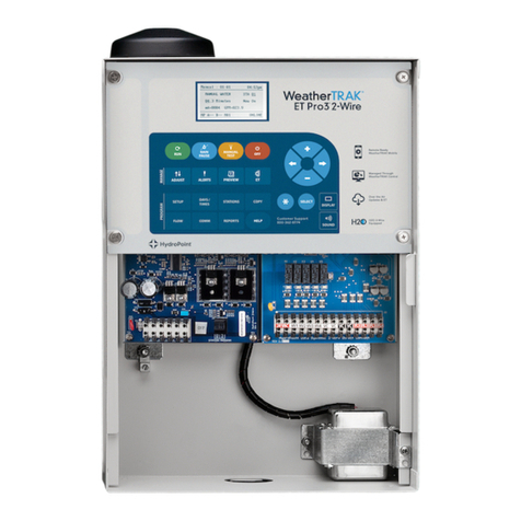
HydroPoint WeatherTRAK ET Pro3 User manual

HydroPoint

HydroPoint WeatherTRAK ET Pro3 User manual

HydroPoint WeatherTRAK 2-Wire User manual

HydroPoint

HydroPoint WeatherTRAK 2-Wire User manual

HydroPoint WeatherTRAK Chassis 7 User manual

HydroPoint

HydroPoint WeatherTRAK Chassis 7 User manual

HydroPoint WeatherTRAK ET Pro2 User manual

HydroPoint

HydroPoint WeatherTRAK ET Pro2 User manual

HydroPoint WeatherTRAK LC Controller User manual

HydroPoint

HydroPoint WeatherTRAK LC Controller User manual

HydroPoint WeatherTRAK ET Pro2 SWM User manual

HydroPoint

HydroPoint WeatherTRAK ET Pro2 SWM User manual

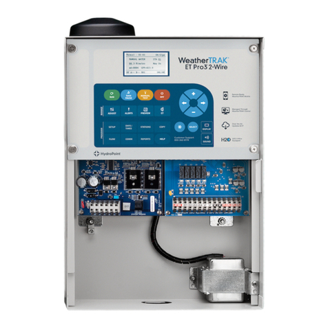
HydroPoint WeatherTRAK ET Pro3 2-Wire User manual

HydroPoint

HydroPoint WeatherTRAK ET Pro3 2-Wire User manual

Popular Controllers manuals by other brands

Siemens SIRIUS 3RW5 series manual

Siemens

Siemens SIRIUS 3RW5 series manual

Roger CPR32-SE v3.0 user manual

Roger

Roger CPR32-SE v3.0 user manual

Tekmar Mixing Control 354 Data brochure

Tekmar

Tekmar Mixing Control 354 Data brochure

Infineon XDPP1100 user manual

Infineon

Infineon XDPP1100 user manual

SM Pro Active-1 operating manual

SM Pro

SM Pro Active-1 operating manual

Eaton LMR PLUS O & M Manual

Eaton

Eaton LMR PLUS O & M Manual

ESYLUX SmartDriver Series operating instructions

ESYLUX

ESYLUX SmartDriver Series operating instructions

RLE Technologies Falcon F200 Quick start guides

RLE Technologies

RLE Technologies Falcon F200 Quick start guides

Newport MM4006 user manual

Newport

Newport MM4006 user manual

BIFFI ALGA - EAC Installation, operation and maintenance manual

BIFFI

BIFFI ALGA - EAC Installation, operation and maintenance manual

Moore Industries 532 user manual

Moore Industries

Moore Industries 532 user manual

Swegon CONDUCTOR W4 Series Installation instruction

Swegon

Swegon CONDUCTOR W4 Series Installation instruction

Beninca YAK 25 OTI manual

Beninca

Beninca YAK 25 OTI manual

Evco EVD HP Installer manual

Evco

Evco EVD HP Installer manual

Enttec PIXEL PORT user manual

Enttec

Enttec PIXEL PORT user manual

Elos me LESCOLTON ICECOOL II DUAL SYSTEM user guide

Elos me

Elos me LESCOLTON ICECOOL II DUAL SYSTEM user guide

Bosch Access Modular Controller 2 installation manual

Bosch

Bosch Access Modular Controller 2 installation manual

EYC DPME02 Operation manual

EYC

EYC DPME02 Operation manual

manuals.online logo
manuals.online logoBrands
  • About & Mission
  • Contact us
  • Privacy Policy
  • Terms and Conditions

Copyright 2025 Manuals.Online. All Rights Reserved.