manuals.online logo
Brands
  1. Home
  2. •
  3. Brands
  4. •
  5. Hydrotec
  6. •
  7. Control Unit
  8. •
  9. Hydrotec HY-MAG Competition User manual

Hydrotec HY-MAG Competition User manual

- 1 -
Operating Instruction
HY-MAG
Competition
Serial number: _______________
HYDROTEC
Hydrotec House
4-5 Manor Courtyard
Hughenden Avenue
High Wycombe
HP13 5RE
Tel. 01494 / 796040 Fax 01494 / 796049
- 2 -
General
Our control box type HY-MAG Competition is a high-quality menu and micro-processor controlled
control box providing maximum efficiency for the HY-MAG Water Conditioning Units sizes DN20
to DN65. The control box is set ex works to the individual water conditioning units.
The instruction render a survey on the menu guide and the individual programming possibilities
for the operator.
The control box shall only be started if the Harting plug connection between control box itself and
water conditioning unit is closed! Insert Harting connection of the control box into the correspond-
ing bushing at the water conditioning unit and close safety bracket.
NOTE : The HY-MAG Competition control box is provided with a transparent
plastic glass. To be able to change or set control operations, the plastic
cover must be opened with the right-hand closure.
Once setting has been finished, the glass must be closed again with an
audible noise.
Initiating phase
Once the control box was connected to the mains power and switched on, the initiating phase
and an initial system check is started automatically. Every individual and actually running operat-
ing sequence is shown in the LCD –display.
Standard display :
Control box test :
Short-circuit test :
Operation - test: Technical operation check of complete HY-MAG system (control box and
water conditioning unit). The below individual sequences are shown
Test current to water conditioning unit See
list of individual current rates for units
(nom. width)
Pre-set water conditioning unit –
example HY-MAG DN20/25
Check remanence clearance
H Y D R O T E C
Competition V. 1.00
Short-circuit - test
Test OK
Control box - test . . . .
Control box OK
Actor –test
current: xxx mA
Actor –test
Hydromag type: DN 20/25
Actor –test
Time reman. clearance: OK
- 3 -
Normal operation
The control box automaticallyswitches to normal operation once the initiating phase has elapsed,
whereby the individual actual operation sequencesare shown in the display and bythe LED lights.
The individual operation phases are shown optically. The below display monitoring is shown dur-
ing continuous operation.
LED –light sequence Display monitor
All 8 LED’s light successively (GREEN phase),
positive d.c. (approx. 100 V) is released to the
water part
Duration about 8 s
Monitoring of day, date and time
Operation state Monitoring current
The current ratings for the corresponding HY-MAG types are
shown in the below list
REFIT®–Phase
Duration about 2 s (magnetic remanence clear-
ing, LED extinguishes successively to the left
within 2 seconds –GREEN LED)
All 8 LED’s light successively (RED), negative
d.c. (approx. 100 V) is released to the water part
Duration about 8 s
REFIT®–Phase
Duration about 2 s (magnetic remanence clear-
ing, LED extinguishes successively to the left
within 2 seconds –RED LED)
The shown current rating is dependent on the type of water conditioning unit.
HY-MAG DN20 / DN25 235 mA ± 10%
HY-MAG DN32 / DN40 345 mA ± 10%
HY-MAG DN50 / DN65 465 mA ± 10%
Thu 11.10.2001 10:30
Cont. operation + xxx mA
Thu 11.10.2001 10:30
Cont. operation + 0mA
Thu 11.10.2001 10:30
Cont. operation - xxx mA
Thu 11.10.2001 10:30
Cont. operation - 0mA
- 4 -
Menu sequences
Input and programming of HY-MAG Competition control box by pressing the front foil buttons
(behind transparent cover) as below:
Call up menu.
Return from the individual menu levels.
Clear parameters.
Selection of individual menu sequences in menu levels, modification
and setting of parameters.
Selection of individual menu sequences in menu levels, modification
and setting of parameters.
Retrieval of individual menu sequences, confirmation/ acknowedge-
ment of settings
NOTE: The monitoring returns to Standard Mode if input is delayed for more than 30 sec-
onds and standard operation is shown in the display.
Main programme menu
The individual sub-menus are selected in the main menu. The main menu is reached by pressing
the button once.
The below menu sequences can be retrieved by the buttons
Operation mode
Operation hours
Day / Time
Time zones
Language
Service
Main menu
Operation mode
Main menu
Operation hours
Main menu
Day / Time
Main menu
Time zones
Main menu
Language
Main menu
Service
- 5 -
The corresponding menu sequence is retrieved with the button and the respective sub-
menu shown.
Mode of operation
The operator can select between 3 different operation modes for the HY-MAG water conditioning
units.
Continuous
operation HY-MAG operates on a continuous 24 hour/day basis
Timer control The control box isin standby mode (LED standby). Switch-on and –off times
are controlled by the internal timers.
One switch-on and –off time per day can be programmed.
Operation off No operation of HY-MAG - no water treatment/conditioning. Such operation
mode shall not be selected and set for normal operation but exclusively for
test mode!
The above operation modes can be selected by pressing the buttons and the correct
mode then be confirmed and acknowledged by pressing the button once.
The control box and/or monitoring returns automatically to main menu after the setting has
been confirmed.
Operating hours
The operating hours of the HY-MAG unit are registered by 2 separate counters.
Absol. value: Total operation time of HY-MAG unit in the actual installation.
(Operation hours since start-up). Standby-times are not registered and
thus, not shown.
Relative value Operating hours of unit counted from a certain period of time.
The counter can be reset by the operator. (Operating hours since
last reset).
The below display is shown after the main menu sequence ‘operating hours’is retrieved:
Operation mode
Continuous operation
Operation mode
Timer control
Operation mode
Conditioning off
Oper. hours abs 000250
Oper. hours rel 000015
- 6 -
The operator is in a position to reset the relative operating hours by pressing the button
once and the relative operating hours counting from the last reset are shown in the display.
The operating hours can be cleared by pressing the button once or the buttons also is used
to reach and return to the previous display.
Clearing the relative operating hours results in an automatic store and monitoring in line 2 of the
actual time of clearing.
Date / Time
The operator can alter the internal timer and the date as described below. The main menu Date /
Time must initially be retrieved, whereby the display shows the actual setting.
If the setting is to be altered, press the button and should no modification be requested, the
sub-menu can be left by pressing the button .
The active field that can be altered is marked with a line underneath. Alter the setting by pressing
the buttons or until the desired figure is visible. The setting is finished once the Cursor
is not flashing anymore. The mode is achieved by pressing the corresponding button . The
menu can be left by pressing the button once.
NOTE: If the button is pressed during the modification phase, the input is interrupted
and the changed figures not be registered.
000015 oper. hours since
08.10.2001 14:50
000000 oper. hours since
10.10.2001 09:40
Date: Wed 10.10.2001
Time: 09:45
Date: Wed 10.10.2001
Time: 09:45
- 7 -
Time zones
The switch-on and –off times of the unit can be programmed in the menu ‘Time zones’after the
operation mode ‘Timer control’was retrieved. One such setting is possible per day.
A group of several days or also individual days can be programmed by the operator. Switch-on
and switch-off times are controlled and initiated by the internal timer.
Groups: Mo ... Su
(several days)
Mo ... Fr
Sa ... Su
Individual days: Mo, Tue, Wed, Thu, Fr, Sa, Su
and so on –for every day in the week.
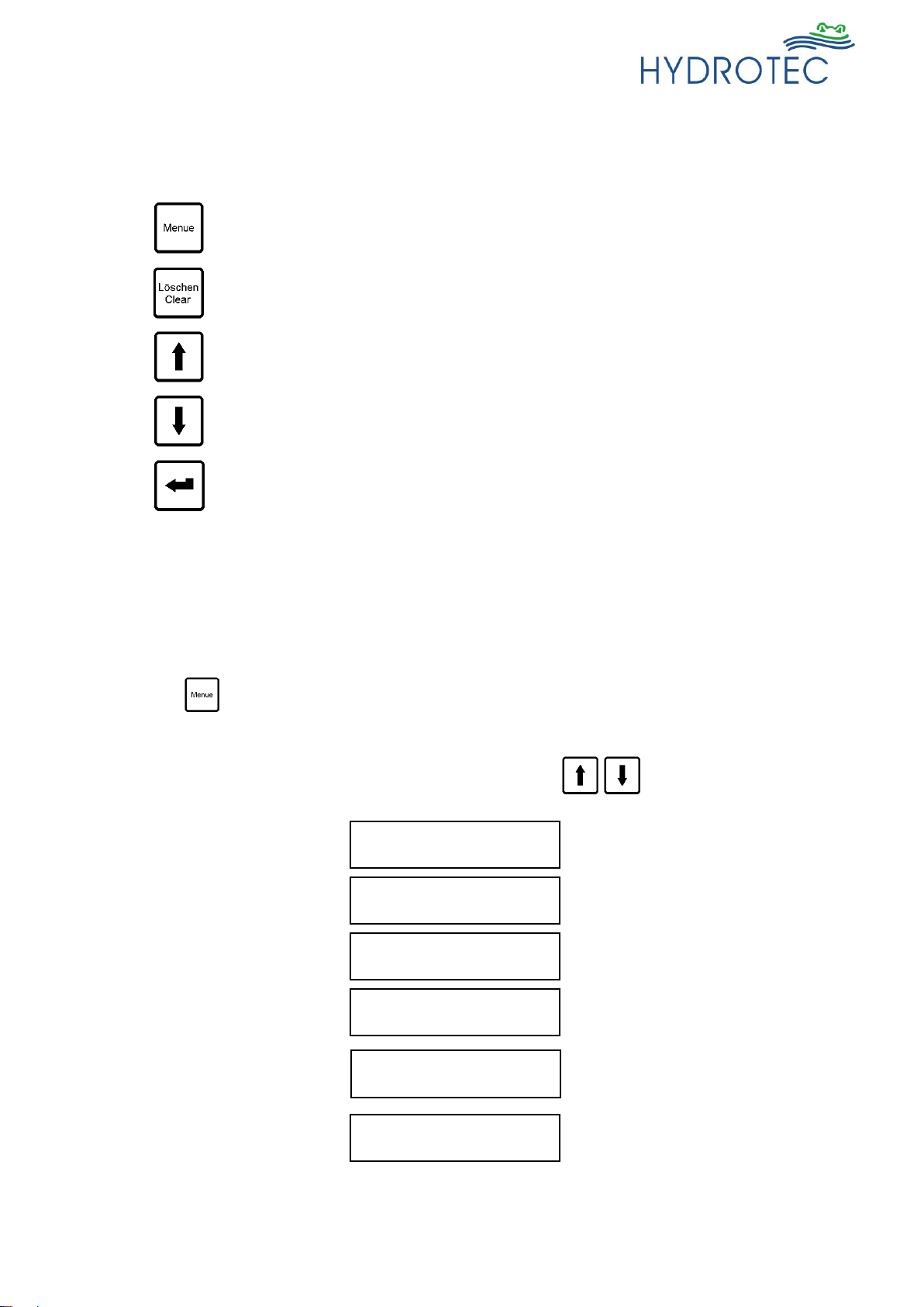
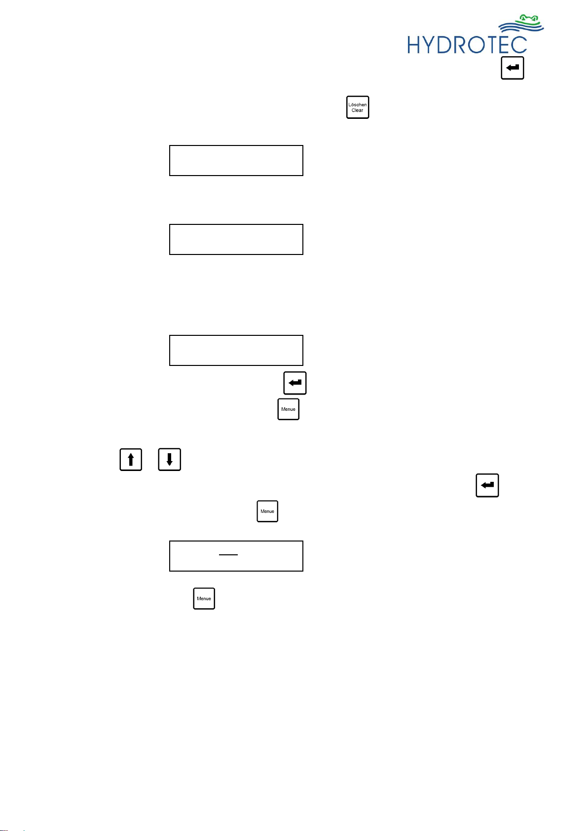
An initial selection of the desired menu is possible with the Cursor buttons , the menu
is then retrieved by pressing the button once and the switching times can then be altered
with the Cursor buttons. The figure that can actually be altered is marked with a line underneath.
Once the correct setting is achieved, the button must be pressed until the line underneath
is no longer visible. If the total switch settings for the selected and retrieved group of days /indi-
vidual day are to be cleared, press the button once.
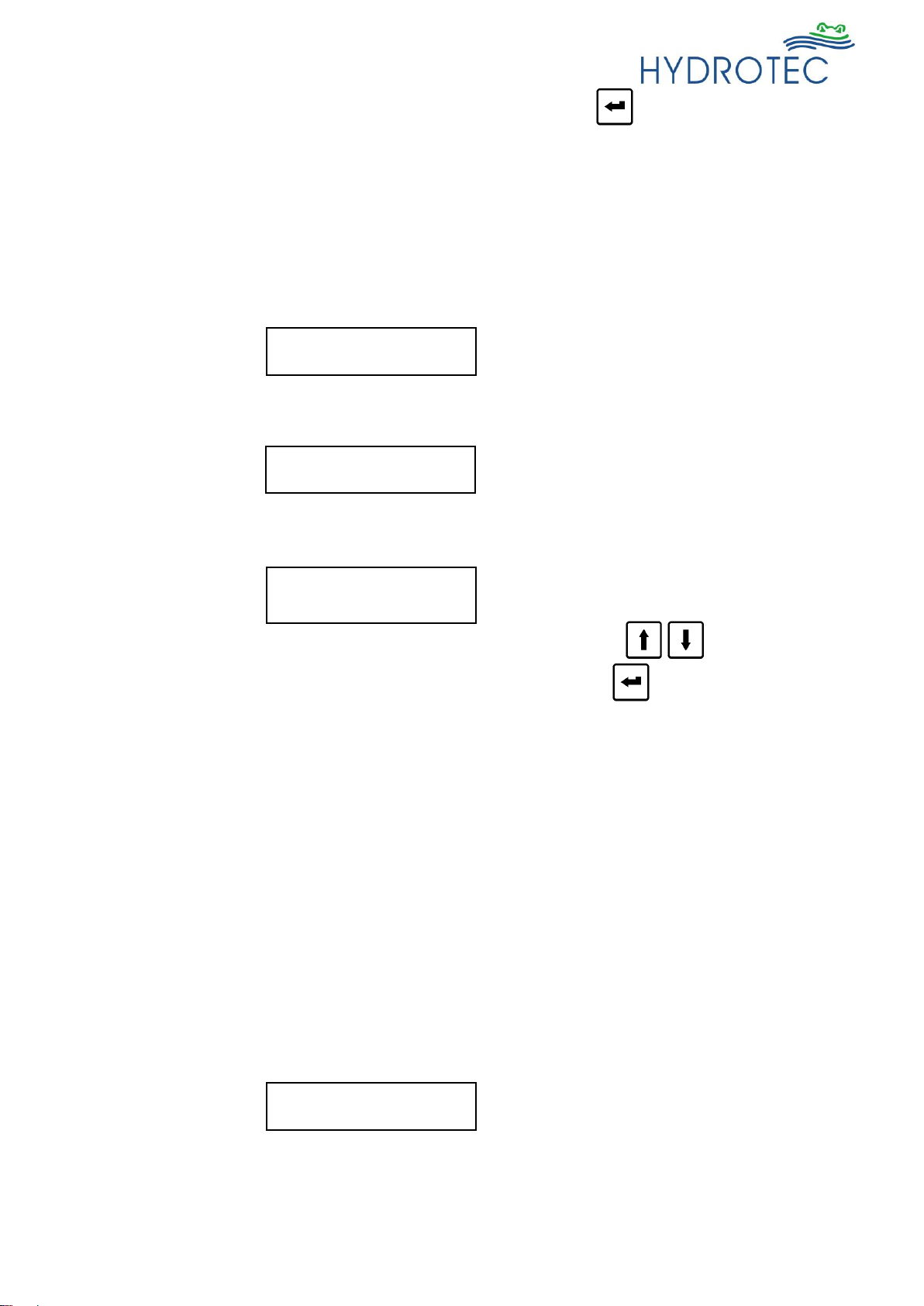
The times for switch-on and switch-off can be selected right on the dot. Below is an example for
setting switch time - group of days Mo-Su, switch-on 6.00 a.m., switch-off 10.00 p.m.
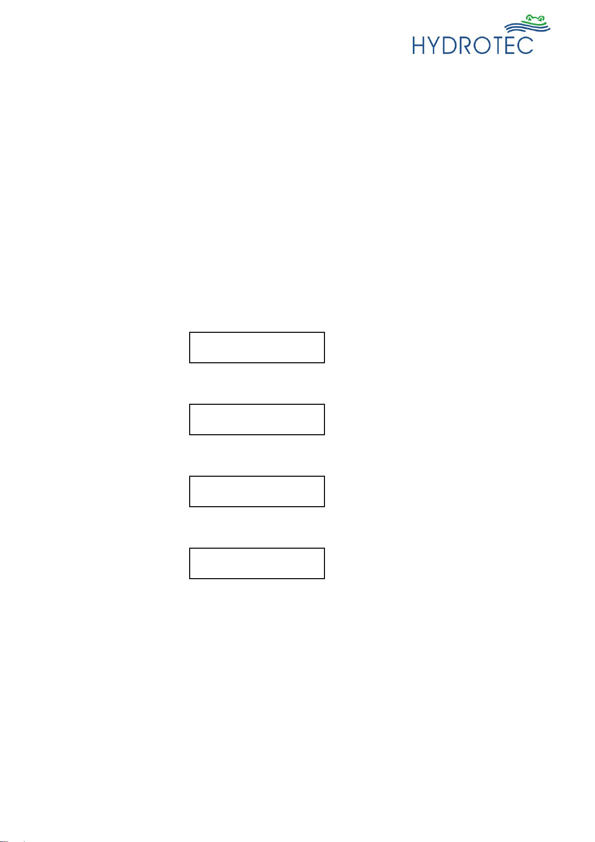
NOTE: If times different to the individual days than provided in the corresponding group of
days are set, the displayfor the group of days show**:**-**:** and the actual switch
time is set in the day monitoring.
If the switch-off time is set earlier than the switch-on time or if the times were reset
(00:00-00:00), the water conditioning unit is not activated that day(s).
Select time zone:
Mo .. Su: **:** - **:**
Select time zone:
Mo .. Fr: **:** - **:**
Select time zone:
Sa .. Su: **:** - **:**
Select time zone:
Mo: **:** - **:**
Alter time zone:
Mo .. Su: 06:00 - 22:00
- 8 -
Language
The service menu of the HY-MAG Competition control box provides 2 languages. Operation and
setting possible in both languages.
The menu language is initially be selected by means of the button . The corresponding
language is then selected and confirmed by the buttons or . Once the correct language
is shown, confirm by pressing the button and the setting is finished.
Service
The service menu is code protected and can be retrieved from authorised service personnel only.
NOTE: If the customer or plant operator retrieves the service menu by mistake, no buttons
shall be pressed for 30 seconds and after such time period the HY-MAG Compe-
tition control box returns automatically to standard mode.
Language:
German
Language:
English
Password: . . . . .
- 9 -
Failure Indication
The Competition control box is provided with an automatic failure recognition. The failure type is
shown.
In case of failure, the total LED-scale flashes red and the display shows the type of failure.
Moreover, it is possible to signal a failure via a potential-free contact. The correct connection is
shown in the terminal plan and such relay-contact can be load as below:-
Rated current: 6A
Rated voltage: 250V AC
max. breaking capacity: 1500W (class AC1 –Ohm load)
max. breaking capacity: 300W (class AC15 –electro-magnetic load)
min. breaking capacity: 500mW / 12V / 10mA
Failure 1: Undercurrent
Coil not closed, faulty connection control box → water unit
Failure 2: Overload
Short cut of coil, faulty coil
Failure 3: Short cut
Short cut in coil connection (visible during initialisation)
Failure 4: Control box failure
failure in any electrical component of the control box, e.g. faulty components
Failure: Undercurrent
Thu 11.10.2001 16:17
Failure: Overcurrent
Thu 11.10.2001 16:17
Failure: Short Circ.
Thu 11.10.2001 16:17
Failure: Control box
Thu 11.10.2001 16:17
- 10 -
Failure –remedial action
General:
If there is no display or should no sign for any operation be visible, initially check the following:
Check whether or not the unit is switched on and mains voltage 230V/50 cps available. If that is
all correct, check the fuse as per the below instruction:
The fuse is provided in the terminal unit on the ledge for the water part connections and mains
supply. Please take care that the mains plug is removed prior to opening the unit! Open the lower
front cover and replace fine fuse (3.15 AT).
If there is still no LED scale visible, inform the technical department of Hydrotec.
Failure 1: Undercurrent
Check connection and correct fit of Harting coupling.
Failure 2: Overload
Failure at magnet coil in water unit. Inform Hydrotec immediately in that case since there are no
further local steps possible.
The first time the failure had been recognised must be noted.
Disconnect unit from mains voltage
Failure 3: Short cut
Short cut (external) of coil circuit
Disconnect unit from mains supply. Check for foreign particles in connection (spiral cable of con-
trol box and connection socket of water unit).
Restart unit. Hydrotec have to be informed immediately if the failure arises again. There are no
further local measures necessary. Disconnect the unit from mains supply.
Failure 4: Control box
Faulty control box. Return box for inspection to Hydrotec along with corresponding failure report
or other information.
Supply conditioning unit
Supply main voltage
Voltage free contact
Fuse 3,15 AT

Popular Control Unit manuals by other brands

Flowserve ColdFlow 341000 User instructions

Flowserve

Flowserve ColdFlow 341000 User instructions

Portwell PQ7-M102XL Series user manual

Portwell

Portwell PQ7-M102XL Series user manual

Ecolab EMP Kompakt II operating instructions

Ecolab

Ecolab EMP Kompakt II operating instructions

Cisco WS-SVC-ASA-SM1-K7 Installation note

Cisco

Cisco WS-SVC-ASA-SM1-K7 Installation note

motogadget mo.rear instruction manual

motogadget

motogadget mo.rear instruction manual

Burkert 2100 series quick start

Burkert

Burkert 2100 series quick start

Sendum PT300D operating manual

Sendum

Sendum PT300D operating manual

Pima MWA500 installation guide

Pima

Pima MWA500 installation guide

Teal Products CCU3 Installation & user manual

Teal Products

Teal Products CCU3 Installation & user manual

ON Semiconductor RSL10 Getting started

ON Semiconductor

ON Semiconductor RSL10 Getting started

Proxim NGP1058 user manual

Proxim

Proxim NGP1058 user manual

Honeywell Maxon SMA11 instruction manual

Honeywell

Honeywell Maxon SMA11 instruction manual

WAGO WAGO-I/O-SYSTEM 750 Series manual

WAGO

WAGO WAGO-I/O-SYSTEM 750 Series manual

Siemens SIMATIC ET 200AL manual

Siemens

Siemens SIMATIC ET 200AL manual

FireAngel WTSL-SN-1 Installation and user guide

FireAngel

FireAngel WTSL-SN-1 Installation and user guide

Harvia sentiotec Pro C2 Instructions for installation and use

Harvia

Harvia sentiotec Pro C2 Instructions for installation and use

IFM CompactLine AC2485 operating instructions

IFM

IFM CompactLine AC2485 operating instructions

BRAHMA EG25 Series manual

BRAHMA

BRAHMA EG25 Series manual

manuals.online logo
manuals.online logoBrands
  • About & Mission
  • Contact us
  • Privacy Policy
  • Terms and Conditions

Copyright 2025 Manuals.Online. All Rights Reserved.