Printed in U.S.A.
Page 9
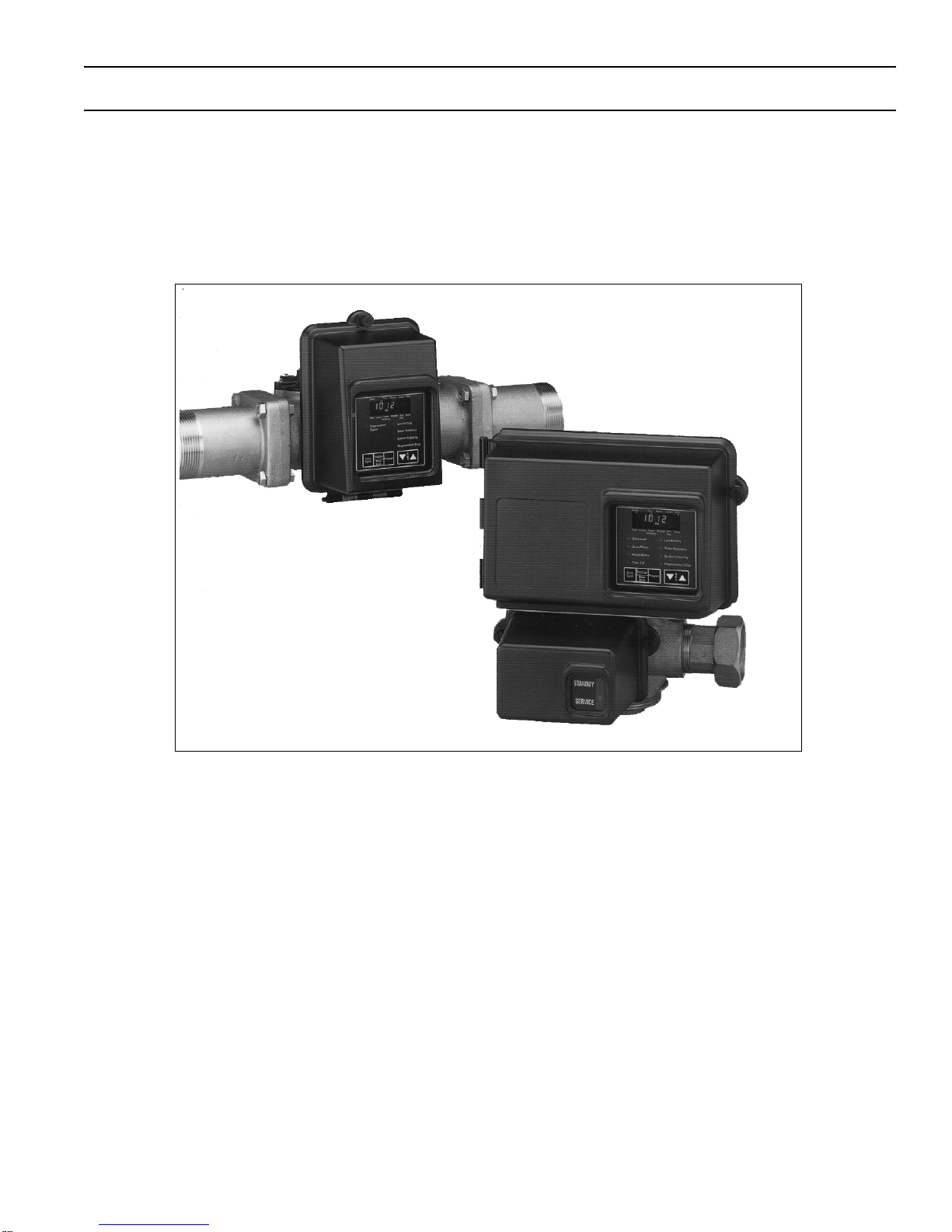
3200ET Control Valve/Remote Meter Timer
Timer/Remote Meter Control Operation
Normal Operation
Flow Meter Equipped Delayed Regeneration Valves/Remote Meter Delayed Regeneration Systems -
In Normal Operation the Time Of Day Display will alternate being viewed with the Volume Remaining Display. Water
flow through the unit is indicated by the Meter Arrow that will flash in a direct relationship to flow rate. As treated water
is used, the Volume Remaining Display will count down from a maximum value to the calculated reserve capacity. Once
this occurs, the Reserve Arrow will begin to flash as an indication that reserve capacity is being used. At the preset
Regeneration Time, a regeneration cycle will then be initiated immediately.
Service Time ReserveTotalizerMeter
RegenLockoutVolume
Remaining
ProgramFlow
Rate Sensor
Backwash
Brine/Rinse
Rapid Rinse
Tank Fill
Low Battery
Water Hardness
System Capacity
Regeneration Time
Extra Totalizer
Flow
Rate
Program S
E
T
Cycle
Service Indicator
Valve in Service - Arrow On
Manual Regeneration Tonight - Flashing Arrow
Time of Day Display Indicator
Reserve Indicator:
Volume Remaining Above Reserve - Arrow Off
Volume Remaining At Or Below Reserve - Arrow Flashing
Totalizer Display Indicator
Flow Indicator:
Arrow Flashes With Water Flow
Sensor Indicator:
Sensor Input Signal - Flashing Arrow
Valid Regeneration Signal - Arrow On
Flow Rate Display Indicator
Program Display Indicator
Volume Remaining Display Indicator
Lockout Indicator:
Lockout Signal - Arrow On
Regeneration Indicator
Valve In Regeneration - Arrow On
Service Time ReserveTotalizerMeter
RegenLockoutVolume
Remaining
ProgramFlow
Rate Sensor
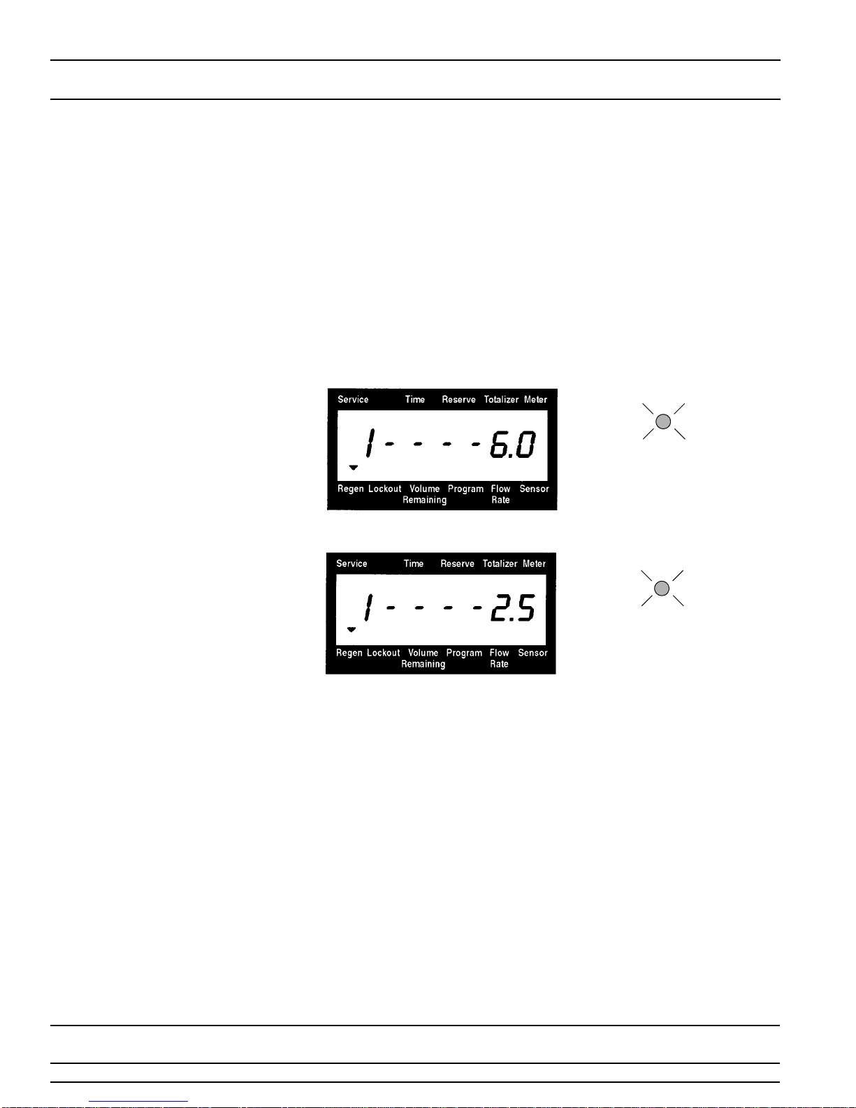
For Example:
125 Gallons of Water Remaining
(Valve in Service)
(No water flow)
(Volume is below reserve capacity)
ET064-0
Timer
ET003-0
Service Time ReserveTotalizerMeter
RegenLockoutVolume
Remaining
ProgramFlow
Rate Sensor
For Example:
0 Gallons of Water Remaining
(Valve in Service)
(Water flowing, Meter arrow flashing)
(Volume is below reserve capacity)
ET007-0
Sensor Indicator:
Sensor Input Signal - Flashing Arrow
Valid Regeneration Signal - Arrow On
Flow Rate Display Indicator
Volume Remaining Display Indicator
Lockout Indicator:
Lockout Signal - Arrow On
Regeneration Indicator
Valve In Regeneration - Arrow On
ET006-0
Program Display Indicator
Service Indicator
Valve in Service - Arrow On
Manual Regeneration Tonight - Flashing Arrow
Time of Day Display Indicator
Reserve Indicator:
Volume Remaining Above Reserve - Arrow Off
Volume Remaining At Or Below Reserve - Arrow Flashing
Totalizer Display Indicator
Flow Indicator:
Arrow Flashes With Water Flow
Remote Meter