MultiSystem 8050
Operating Instructions Manual
© Hydrotechnik GmbH All rights reserved Page 3 of 62
Rev. 2.5 EN • Firmware version 3.3
8.6 HYDROlink operation menus.......................................................................................... 59
8.6.1 Program menu................................................................................................................59
8.6.2 Menus menu...................................................................................................................59
8.6.3 View menu......................................................................................................................59
8.6.4 Instruments menu...........................................................................................................59
8.6.5 Configuration menu ........................................................................................................59
8.6.6 HYDROrun menu............................................................................................................60
9Technical Data ..............................................................................................................61
Illustrations
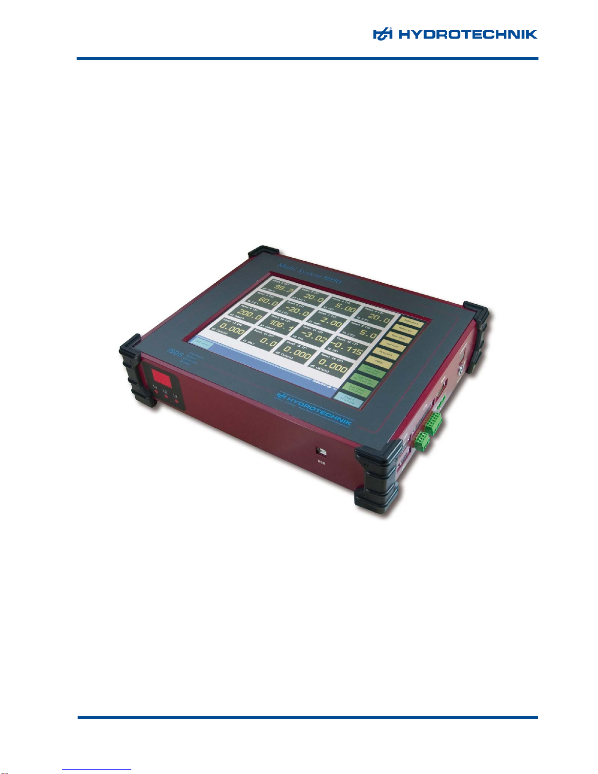
Pic. 1 Front view.........................................................................................................................8
Pic. 2 Rear view..........................................................................................................................9
Pic. 3 Right-side connectors.......................................................................................................9
Pic. 4 Rear side connectors........................................................................................................9
Pic. 5 Start screen ....................................................................................................................13
Pic. 6 Measuring display...........................................................................................................14
Pic. 7 Elements on the screen..................................................................................................14
Pic. 8 Display mode „TEXT“......................................................................................................15
Pic. 9 Display mode „GRAPHIC“ ..............................................................................................16
Pic. 10 Virtual keyboard..............................................................................................................17
Pic. 11 Virtual 10-key pad...........................................................................................................18
Pic. 12 Channel menu ................................................................................................................18
Pic. 13 Configure analog inputs..................................................................................................19
Pic. 14 Zero point alignment.......................................................................................................20
Pic. 15 Linearisation function......................................................................................................20
Pic. 16 Enter linearisation table ..................................................................................................21
Pic. 17 Configure inputs for voltage/current................................................................................21
Pic. 18 Configure frequency inputs.............................................................................................22
Pic. 19 Configure trigger input ....................................................................................................23
Pic. 20 Configure trigger output..................................................................................................24
Pic. 21 Configure digital inputs ...................................................................................................25
Pic. 22 Configure digital outputs.................................................................................................25
Pic. 23 Configure analog outputs................................................................................................26
Pic. 24 Configure calculated channels........................................................................................27
Pic. 25 Configure CAN channel..................................................................................................28
Pic. 26 Display menu..................................................................................................................29
Pic. 27 Adapt scaling..................................................................................................................30
Pic. 28 Assign colors and symbols .............................................................................................31
Pic. 29 Set contrast.....................................................................................................................32
Pic. 30 Memory menu.................................................................................................................32
Pic. 31 Define trigger..................................................................................................................33
Pic. 32 Device menu...................................................................................................................34
Pic. 33 Set channel filters ...........................................................................................................35
Pic. 34 Hardware setup ..............................................................................................................36
Pic. 35 Compact Flash information.............................................................................................37
Pic. 36 Project menu...................................................................................................................38
Pic. 37 HYDROrun menu............................................................................................................39
Pic. 38 Release HYDROrun .......................................................................................................40
Pic. 39 Delete test procedures....................................................................................................41
Pic. 40 Initiate recording.............................................................................................................42
Pic. 41 Present series of measurement......................................................................................43
Pic. 42 Select measurement data...............................................................................................44
Pic. 43 Adapt presentation parameters.......................................................................................45
Pic. 44 Adapt scaling..................................................................................................................46
Pic. 45 Adapt graphic settings ....................................................................................................47
Pic. 46 Graph y = f(t) ..................................................................................................................48
Pic. 47 Use spot values..............................................................................................................49
Pic. 48 Use delta spot values .....................................................................................................50
Pic. 49 Graph y = f(x)..................................................................................................................51
Pic. 50 Table...............................................................................................................................51
Pic. 51 Select intermediate values..............................................................................................52
Pic. 52 Intermediate values ........................................................................................................52
Pic. 53 Display statistical data ....................................................................................................53
Pic. 54 Starting a test procedure.................................................................................................54