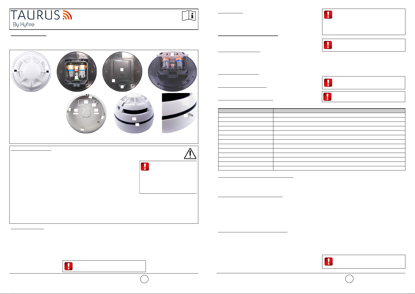
POWERING UP - FIRST TIME USE - WITHOUT INSULATING TAB
Use this procedure the first time you power up a TAU-MC-01-BL; the detector has not been supplied with the insulating tab.
1) Make sure the Link / program switch is set on “ON”.
2) Insert the two supplied batteries into their device’s lodgments.
POWERING UP - DEVICE LINKED TO THE SYSTEM
Use this procedure when a TAU-MC-01-BL is successfully linked to its Taurus system and you have to extract one or both batteries (e.g.
batteries substitution).
1) Reinsert the battery or both batteries into their lodgments.
If performing a batteries substitution, use two brand new batteries and substitute both of them.
Do not touch the Link / program switch.
POWERING UP - RECOVERY
Use this procedure when you fail to link successfully a TAU-MC-01-BL or you want to link it again.
1) Move alternatively the Link / program switch 5 times.
2) Set the Link / program switch on “ON”.
3) Insert the two supplied batteries into their device’s lodgments.
LINKING - WAKE-UP - WITHOUT INSULATING TAB
“Wake-up” linking consists in associating one or more child devices to the Taurus system altogether in a single operation.
Wake-up is performed either through the TauREX software or the TAU-TRM-01 / TAU-CEM-01 keyboard-screen interface; it CANNOT be
done through TAU-EXM-01 devices.
1) Create the “virtual model” of the TAU-MC-01-BL either on TauREX or on the TAU-TRM-01 / TAU-CEM-01.
2) Power-up the detector (either “first time use” or “recovery”).
3) Set the Link / program switch OPPOSITE to “ON”.
4) Trigger the wake-up procedure either from TauREX or from the TAU-TRM-01 / TAU-CEM-01.
5) Wait the end of the “wake-up” linking procedure.
6) Check on TauREX or from TAU-TRM-01 / TAU-CEM-01 for linking success. Consult their user manual.
LINKING - ONE-BY-ONE - WITHOUT INSULATING TAB
“One-by-one” linking consists in associating one child device at a time to the Taurus system.
This operation is performed either through the TauREX software or the TAU-TRM-01 / TAU-CEM-01 keyboard-screen interface; it CANNOT
be done through TAU-EXM-01 devices.
1) Create the “virtual model” of the child device either on TauREX or on the TAU-TRM-01 / TAU-CEM-01.
2) Trigger the linking procedure either from TauREX or from the TAU-TRM-01 / TAU-CEM-01.
3) Power-up the child device (either “first time use” or “recovery”).
4) Set the child device’s Link / program switch OPPOSITE to “ON”.
5) Wait the end of the “one-by-one” linking procedure.
6) Check on TauREX or from TAU-TRM-01 / TAU-CEM-01 for linking success. Consult their user manual.
TESTING
Magnet test
1) Activate test mode.
2) Apply again the magnet in correspondence of the “magnet test activation area”.
3) LED indicators signal “Alarm activation”.
Aerosol test
1) Activate test mode.
2) Apply the aerosol test device to the detector.
3) Wait a few seconds.
4) LED indicators signal “Alarm activation”.
Heat test
1) Activate test mode.
2) Apply the heat test device to the detector.
3) Wait a few seconds.
4) LED indicators signal “Alarm activation”.
BATTERY FAULTS AND BATTERY SUBSTITUTION PROCEDURE
When one or both batteries are low in charge, a specific fault message is routed to the control panel. If such event occurs:
1) Remove the safety screw.
2) Remove the detector from its base.
3) Remove the batteries cover.
4) Extract both batteries.
5) Insert both new batteries into their holders, oriented as per polarity marks.
See POWERING UP - DEVICE LINKED TO THE SYSTEM.
6) Reinstall the batteries cover.
7) Reinstall the detector.
8) Reinstall the safety screw.
Local safety standards may require you
to test these devices on a regular basis.
Use only suitable aerosol testers / heat test
devices supplied by approved manufacturers.
Follow their specific use instructions.
Before testing every TAU-MC-01-BL,
always activate test mode. This is done
by holding a suitable magnet in the
“magnet test activation area”. When activated,
LED indicators signal “Test mode active”.
When a low battery condition is indicat-
ed, both batteries must be changed
altogether.
Batteries must be brand new.
Do not touch the Link / program switch.
Ensure that the batteries are installed properly,
with their polarities matching the indications on
the device.
Always ensure that the batteries are
installed properly, with their polarities
matching the indications on the device.
Hyfire Wireless Fire Solutions Ltd - Unit B12a, Holly Farm Business Park, Honiley,
Warwickshire, CV8 1NP - United Kingdom
www.hyfirewireless.com
3
MAINTENANCE - CLEANING
1) Remove the safety screw.
2) Remove the detector from its base.
3) Smoke entry areas and thermistor area: use a small, soft bristle brush to dislodge any obvious contaminants such as insects, spider webs,
hairs, etc.
4) Smoke entry areas and thermistor area: use a small vacuum tube or dry, clean, compressed air to suck up or blow any remaining small
particles away.
5) Wipe the exterior housing of the detector with a clean, damp, lint-free cloth to remove any surface film that can later attract airborne
contaminants.
6) Install the detector onto its base again.
7) Test the detector.
8) Reinstall the safety screw.
TECHNICAL SPECIFICATIONS *
*See TDS-TWDMX technical specification document for further technical data.
BATTERIES SPECIFICATIONS
*Batteries lifespan depends by environmental conditions, default monitor settings and link quality.
SMOKE SENSITIVITY SPECIFICATIONS
*Detector’s smoke sensitivity can be set through TauREX.
Specification Value
Communication range with TAU-TRM-01, TAU-CEM-01 or
TAU-EXM-01 network devices 200 m (in open space)
Wireless frequency band 868 MHz
Number of wireless channels 66
Radiated power 14 dBm (25 mW)
Temperature alarm threshold (static) 58 °C
Operating temperature range -10 °C to 55 °C
Maximum humidity (non condensing) 95% RH
IP rating 40
Specification Value
Batteries type CR123A (3 V, 1.25 Ah)
Batteries lifespan * 10 years
Low battery threshold value (nominal) 2.850 V
Detector’s sensitivity setting * Obscuration threshold value for alarm activation
High sensitivity 0.12 dB/m
Medium sensitivity (default setting) 0.15 dB/m
Low sensitivity 0.18 dB/m
Table 2
Table 3
Table 4
WARNINGS AND LIMITATIONS
Our devices use high quality electronic components and plastic materials that are highly resistant to
environmental deterioration. However, after 10 years of continuous operation, it is advisable to
replace the devices in order to minimize the risk of reduced performance caused by external factors.
Ensure that this device is only used with compatible control panels. Detection systems must be
checked, serviced and maintained on a regular basis to confirm correct operation. Smoke detectors
may respond differently to various kinds of smoke particles, thus application advice should be sought
for special risks. Detectors cannot respond correctly if barriers exist between them and the fire
location and may be affected by special environmental conditions. Refer to and follow national codes
of practice and other internationally recognized fire engineering standards. Appropriate risk assess-
ment should be carried out initially to determine correct design criteria and updated periodically.
Use only in Taurus fire detection and alarm systems.
WARRANTY
All devices are supplied with the benefit of a limited 5 years warranty relating to faulty materials or
manufacturing defects, effective from the production date indicated on each product. This warranty is
invalidated by mechanical or electrical damage caused in the field by incorrect handling or usage.
Product must be returned via your authorized supplier for repair or replacement together with full
information on any problem identified. Full details on our warranty and product’s returns policy can
be obtained upon request.
Hyfire Wireless Fire Solutions Ltd - Unit B12a,
Holly Farm Business Park, Honiley, Warwick-
shire, CV8 1NP - United Kingdom
TAU-MC-01-BL
EN 54-25:2008
EN 54-7:2018
EN 54-5:2017+A1:2018
Class A1R
4
0051
22
HF-20-014CPR