Hypex Electronics DIYclassD PreAmplifier Basic kit User manual

Basic kit
User
Manual

32
Correct disposal of this product: This symbol indicates that this product should not be disposed of with your household waste, according to the
WEEE directive (2012/19/EU) and your national law. This product should be handed over to an authorized collection site for recycling waste
electrical and electronic equipment (EEE). Improper handling of this type of waste could have a possible negative impact on the environment
and human health due to potentially hazardous substances that are generally associated with EEE. At the same time, your cooperation in the
correct disposal of this product will contribute to the effective usage of natural resources. For more information about where you can drop off
your waste equipment for recycling, please contact your local city office, waste authority, or your household waste disposal service.
- Correct connections of all cables.
Do not use this apparatus near water.
Do not install near any heat sources such as radiators,
heat registers, stoves, or other apparatus (including
amplifiers) that produce heat.
Refer all servicing to qualified service personnel.
Servicing is required when the apparatus has been
damaged in any way, such as power-supply cord or plug
is damaged, liquid has been spilled or objects have fallen
into the apparatus, the apparatus has been exposed to
rain or moisture, does not operate normally, or has been
dropped.
Never connect a power cord to this apparatus before
Natural convection should not be impeded by covering
the module (apart from the end applications housing).
Do not block any ventilation openings. Install in
accordance with the manufacturer’s instructions.
This apparatus shall not be exposed to dripping or
splashing, and no object filled with liquids, such as vases
or beer glasses, shall be placed on the apparatus.
Only use attachments/accessories specified by the
manufacturer.
Do not overload wall outlets and extension cords as this
can result in a risk of fire or electric shock.
the assembly is finished wich include:
Unplug this apparatus during lightning storms or when
unused for long periods of time.
Do not defeat the safety purpose of the protective earth
/ grounding mains inlet. Protective earth is provided for
your safety.
Clean only with a dry cloth.
Protect the power cord from being walked on or pinched
particularly at plugs, convenience receptacles, and the
point where they exit from the apparatus.
- Proper installation of all parts.
- Firmly closed case.
This apparatus has been equipped with a rocker-style AC
mains power switch. This switch is located on the rear
panel and should remain readily accessible to the user.
Before using this product, ensure all cables are correctly
connected and the power cables are not damaged. If you
detect any damage, do not use the product.
The MAINS plug or an appliance coupler is used as the
disconnect device, so the disconnect device shall remain
readily operable.
Do not run any cables across the top or the bottom of the
module. Apply fixtures to cables to ensure that this is not
compromised.
This apparatus has been designed with Class-I
construction and must be connected to a mains socket
outlet with a protective earthing connection.
Changes or modifications not expressly approved by
Hypex Electronics will void compliance and therefore the
user's authority to operate the equipment.
Service or modifications by any person or persons other
than by Hypex Electronics authorized personnel voids the
warranty.
6.
7.
5.
8.
10.
12.
13.
9.
14.
11.
23.
16.
17.
15.
.
20.
18.
21.
19.
22.
Follow all instructions.
Head all warnings.
Keep these instructions.
Read these instructions.
4.
3.
2.
1.
Gebruik voor dit apparaat een geaard stopcontact.
Verwenden Sie für dieses Gerät eine geerdete
Utilisez une prise électrique mise à la terre pour cet
appareil.
Utilice un tomacorriente con conexión a tierra para
este aparato.
Use a grounded electrical outlet for this appliance.
The exclamation point within an equilateral triangle is
intended to alert the user of the prescence of important
operating and maintaining (servicing) instructions in
the literature accompanying the appliance.
The lightning flash with arrowhead symbol within an
equilateral triangle is intended to alert the user to the
prescence of uninsulated “dangerous voltage” within
the product’s enclosure, that may be of significant
magnitude to constitute a risk of electric shock to
persons.
Ce unité est sous tension secteur et certaines de ses
pièces accessibles sont sous une tension dangereuse.
Ces pièces doivent dans tous les cas être protégées
contre contacts accidentels. Lors de l'installation, une
prudence extrême s'impose. Ne jamais toucher les pièces
du module quand celui-ci est relié au secteur. Isoler
l'appareil du secteur et attendre 10 minutes pour laisser
à tous les condensateurs le temps de se décharger avant
de le manipuler.
Les dommages causés par un usage non approprié sont
exclus de la garantie. Ce Produit ne contient aucune
pièce devant être entretenue par l'utilisateur.
Précautions de sécurité
Avertissement: Pour réduire les risques de choc électrique, ne
pas exposer cet appareil à la pluie ou l'humidité.
Warning: To reduce the risk of fire or electric shock, do not
expose this device to rain or moisture.
Damage due to inappropriate handling is not covered by
warranty. This product has no user-serviceable parts.
This unit operates at mains voltage and carries
hazardous voltages at accessible parts. These parts may
never be exposed to inadvertent touch. Observe extreme
care during installation and never touch module of the
unit while it is connected to the mains. Disconnect the
unit from the mains and allow all capacitors to discharge
for 10 minutes before handling it.
Safety precautions
Chapter
Page
System
10
Balance
10
Display
10
Brightness
10
Off Time-out
10
LED
11
Factory reset
11
About
11
4. Setup example
12
5. System information
13
6. Additional System information
13
Troubleshooting
14
Frequently asked questions
14
Support
14
Warranty
15
Disclaimer
15
Revisions
15
Notes
15
Contact
16
Chapter
Page
Introduction, Table of contents
2
Safety precautions
3
1. Connections & Control
4
Front
4
Back
4
Remote
5
2. Function
6
On/Off/Standby/Idle
6
Volume/Mute
6
Input select
7
Headphones
7
3. Configuration
7
Navigation
7
Inputs
8
Source
8
Routing
8
Gain offset
9
Trigger
9
Restore defaults
9
Table of Contents
1x Supply board
This User Guide.
Power cable
Interconnects
1x Hypex Remote Control incl battery
1x Main board
1x Front board
1x Headphones board
Not included in the kit
Included in the kit
Trigger cables
All required connectors
1x DIY PreAmplifier case
1x TX-10 / TX-20 and 1.5mm hex key
USB service cable
1x Internal cable harness
All required mounting materials
at page 2
User assembly guide
Tools as described in the Assembly Instructions
This User Guide covers the general operation
instructions, how to install and use the DIY
PreAmplifier. For assembly instructions, please refer
to the corresponding Assembly Instructions.
Thank you for purchasing the DIYclassD
PreAmplifier kit, designed by Hypex Electronics.
Please read the safety instructions on the next page
before assembling, installing and/or operating the
DIY PreAmplifier kit.
We have designed a DIY PreAmplifier with great
performance, careful installation and correct use will
help ensure that their full potential is achieved.
DIY Amplifier kit, a brief introductionPre
54
Hypex Remote
Internal use
OK
ON/OFF toggle
Arrow Up
Arrow Down
Mute
Arrow right
Arrow left
F1
F2
F3
PreAmp Function
Reserved
Reserved
Power ON/OFF
Volume UP
Volume DOWN
Mute
Select next input
Select previous input
-
-
-
Code
34
48
50
51
52
53
54
55
56
67
59
Rc5 Codes supported
Device code: 16
Hypex Remote
F4
-
-
-
-
-
-
-
-
-
-
PreAmp Function
-
-
-
-
-
-
-
-
-
-
-
Code
61
18
19
20
21
22
23
24
25
28
29
electronics
hypex
-
+
OK
F1 F2
F3
F4
8
6
5
7
4
3
12
11
10
9
2
1
5: Volume +
1: IR transmitter
2: Power on/off (Standby)
4: Input next
7: Display activate
8: Mute
9: (not used)
11: (not used)
10: (not used)
12: (not used)
6: Volume -
3: Input previous
Remote
The configuration handles
both mono and stereo connectors.
Each output has 2 trigger
Output 1 & 2
2x Male XLR Stereo Balanced Analogue Out
ports to activate 2 different
Trigger 1 & 2
devices simultaneously.
2x dual 3.5mm (1/8") TS
12V/5mAmax Out. Gnd
+12Vdc
3. Signal -
(inverting)
2. Signal +
1. Signal Gnd
Input 3
Input 1 & 2
Female XLR Stereo Balanced Analogue In
2x RCA Unbalanced Analogue In
3. Signal -
(inverting)
1. Signal Gnd
2. Signal +
Release
Input 1
Left
Right
Input 2
Left
Right
(100 - 240Vac)IEC60320/C14
Expansion bay
For future additions
Fuse
T1AH/250V (size 5x20)
Mains inlet & Power switch
the firmware. This connection does not support
USB audio.
Mini-USB
Service Port
Can be used to configure the Pre-amp and update
FuseMains
Expansion
Bay
Output
Service Port
Power
Trigger
Input
Back
Control knob 'B'
Rotate: Volume Up/Down
Press: - Power On
- Volume Mute/Unmute
Long Press: Standby
brightness.
Headphones Connections
- Activate/de-activate
the headphones outputs.
- White light with adjustable
Headphones Activate
1x 6.35mm (1/4") TRS Unbalanced Stereo HP
1x Female XLR 4-pole Balanced Stereo HP
Light
Button
2. Left Gnd
4. Right Gnd
3. Right +
1. Left +
Right +
Gnd
Left +
- Menu Navigation - Select
for included remote control.
- 2.7" Monochrome OLED Display
White light with adjustable brightness.
Infrared Signal Receiver
Power Indicator
Control knob 'A'
Rotate: - Input Select Press: - Menu
- Adjustable brightness and on-time
IR Receiver
Display
Active Output
Active Input
Volume
Main screen
electronics
hypex
-
+
OK
F1 F2
F3
F4
Headphones
Activate
Power
Indicator
Headphones
Control
Knob B
Display
IR
Receiver
Control
Knob A
Front
1. Connections & Control

54
Hypex Remote
Internal use
OK
ON/OFF toggle
Arrow Up
Arrow Down
Mute
Arrow right
Arrow left
F1
F2
F3
PreAmp Function
Reserved
Reserved
Power ON/OFF
Volume UP
Volume DOWN
Mute
Select next input
Select previous input
-
-
-
Code
34
48
50
51
52
53
54
55
56
67
59
Rc5 Codes supported
Device code: 16
Hypex Remote
F4
-
-
-
-
-
-
-
-
-
-
PreAmp Function
-
-
-
-
-
-
-
-
-
-
-
Code
61
18
19
20
21
22
23
24
25
28
29
electronics
hypex
-
+
OK
F1 F2
F3
F4
8
6
5
7
4
3
12
11
10
9
2
1
5: Volume +
1: IR transmitter
2: Power on/off (Standby)
4: Input next
7: Display activate
8: Mute
9: (not used)
11: (not used)
10: (not used)
12: (not used)
6: Volume -
3: Input previous
Remote
The configuration handles
both mono and stereo connectors.
Each output has 2 trigger
Output 1 & 2
2x Male XLR Stereo Balanced Analogue Out
ports to activate 2 different
Trigger 1 & 2
devices simultaneously.
2x dual 3.5mm (1/8") TS
12V/5mAmax Out. Gnd
+12Vdc
3. Signal -
(inverting)
2. Signal +
1. Signal Gnd
Input 3
Input 1 & 2
Female XLR Stereo Balanced Analogue In
2x RCA Unbalanced Analogue In
3. Signal -
(inverting)
1. Signal Gnd
2. Signal +
Release
Input 1
Left
Right
Input 2
Left
Right
(100 - 240Vac)IEC60320/C14
Expansion bay
For future additions
Fuse
T1AH/250V (size 5x20)
Mains inlet & Power switch
the firmware. This connection does not support
USB audio.
Mini-USB
Service Port
Can be used to configure the Pre-amp and update
FuseMains
Expansion
Bay
Output
Service Port
Power
Trigger
Input
Back
Control knob 'B'
Rotate: Volume Up/Down
Press: - Power On
- Volume Mute/Unmute
Long Press: Standby
brightness.
Headphones Connections
- Activate/de-activate
the headphones outputs.
- White light with adjustable
Headphones Activate
1x 6.35mm (1/4") TRS Unbalanced Stereo HP
1x Female XLR 4-pole Balanced Stereo HP
Light
Button
2. Left Gnd
4. Right Gnd
3. Right +
1. Left +
Right +
Gnd
Left +
- Menu Navigation - Select
for included remote control.
- 2.7" Monochrome OLED Display
White light with adjustable brightness.
Infrared Signal Receiver
Power Indicator
Control knob 'A'
Rotate: - Input Select Press: - Menu
- Adjustable brightness and on-time
IR Receiver
Display
Active Output
Active Input
Volume
Main screen
electronics
hypex
-
+
OK
F1 F2
F3
F4
Headphones
Activate
Power
Indicator
Headphones
Control
Knob B
Display
IR
Receiver
Control
Knob A
Front
1. Connections & Control

7
6
moved to the left and right
setting.
appears, this bar can be
Adjusting values
When the vertical bar
according to the desired
Push Control Knob 'A' to confirm the value.
confirmation is needed to
Saving changes
After the parameter is set,
maintain this new value or
discard to readjust to its previous setting.
The effect is noticeable during the adjustments.
Configuration Menu
Press Control Knop 'A' one
time to enter the menu.
direction. Rotate Control Knop 'A'
to jump to the desired option and
and eventually to leave the configuration menu.
Navigate
previous level in the menu
The arrows tell the availability of a
Every (sub)menu ends with 'BACK' at the final
position to return to the
press for confirmation.
Navigation
3. Configuration
* The brightness is set to full by default.
Device: Press the button to
It is adjustable to half and off in the system
The light will turn on* and
set the output signal to
HP Activate/De-activate
configuration.
both HP connectors.
the display shows 'HP'.
switching between
when the device is turned off.
All trigger outputs will be temporarily turned off
when Headphones outputs are active.
HP and XLR.
The HP assignment will remain active when the
Output select
Select the output by
device goes to standby but returns back to XLR
Headphones
Device: Turn Control Knob 'A'
left or right.
Previous/Next
Remote: Press ◄ or ►.
Input adjustments
Change the input by
selecting between
Input '1' up to '3'.
Input Select
Device: Press Control Knob 'B'.
Volume Mute/Unmute
Display:
XLR Headphones
Remote: Press Mute-button.
between -70,0dB and 16,0dB
relative to the input signal.
Device: Turn Control Knob 'B'
left or right.
Volume up/down (stepsize 0.5dB)
Volume adjustments
Remote: Press - or +.
The output volume can set
-
+
Volume/Mute
Device: Press and hold Control Knob 'B'
before turning off.
'Power off...' for 2 sec.
Standby
for at least 2 seconds.
Remote: Press the power button.
wil go off.*
Power Off
The display will show
The power indicator
at the back to turn off
* The brightness of the power indicator is set to
full by default. It is adjustable to half and off in
the system configuration.
the mains power.
Use the power switch
Any saved changes made
in the menu will still remain.
The display will show
Device: Press Control Knob 'B'.
Activate
Remote: Press the power button.
The power indicator
the logo for 2 seconds
will light up.*
screen.
Idle
the mains power.
before showing the main
The brightness of the display will dim after
Use the power switch
at the back to turn on
Power On
To prevent burn-in, the
a configured period and
display will turn off after
1 minute of no operation.
remain on in this case.*
will be activated again
by any action.
The power indicator will
On/Off/Standby/Idle
2. Function

98
Restore any settings in
Source, Routing, Gain
Offset and Triggers to
factory defaults.
This applies only to the
the current selected input:
RESTORE DEFAULTS
The other input and
system settings will
remain.
2
TRIGGER TRIGGER
1
TRIGGER ON/OFF
Which trigger will go ON when the regarding
input is active.*
Select the desired trigger to show the current
status and to adjust it. This will affect both
ports for each corresponding output (1 or 2).
By default, the ports are set to ON for all
inputs.
* During Headphones activation, the
triggerports are temporarily inactive.
Centre: 0dB (default).
Scope
Range: -8dB (left) -> +8dB (Right).
Steps: 60 x 0.25dB.
GAIN OFFSET
Adjust the input signal level to match the
output volume at different input signals.
volume control for safety reasons.
LINE: Signal-in via volume control to output.
Note: Activating headphones will
temporarily reroute the signal through
(default setting)
DIRECT: signal-in = signal-out (volume 0dB)
PHONO: Not available jet. (Used in future add-on)
ROUTING
the input signal
Change the path of
through the pre-amp.
Change the name of the input corresponding to the connected source.
SOURCE
Customize Inputs
Select the desired Input
channel to customize
Inputs

1110
Bundle: Firmware bundle version.
HWV_F: Frontboard Hardware version.
HWV_M: Mainboard Hardware version.
Information about the currently installed
Firmware and Hardware.
ABOUT
WARNING!
It is highly recommended to turn
off any connected devices before
executing the factory defaults to
prevent any unintended effects
due to unpredictable behaviour of
external sources and amplifiers.
After a factory reset, each
connected device should be
configured as before when
connected for the first time.
FACTORY RESET
Restore all settings to factory defaults.
LED
Adjust the brightness of the 2 indicator lights.
DISPLAY
- Determine how much time it takes for the display to turn black after it got dimmed.
OFF TIME-OUT
- When active (BRIGHT. ACT)
- When inactive (BRIGHT. DIM)*
BRIGHTNESS
DISPLAY
*After 20 seconds of not operating
while showing the main screen.
R
Lpreamp
1 step Right: -1dB Left signal output.
Centre: Left & Right = -0dB Gain (default).
1 step Left: -1dB Right signal output.
Scope
BALANCE
Alter the output signal to set the acoustic
centre point to the desired offset.
SYSTEM OPTIONS
Customise various
settings for audio and
visual setup.
System

13
12
6. Additional system information
5. System information
Technical data
* Operation beyond these limits may result in irreversible damage.
All audio measurements are done with AES17 20kHz filter.
Audio performance data
Item
Value
Notes
Supply voltage *
90–135 Vac / 180 –270V ac ( 47-63Hz )
Auto Switching
Standby power
<0.5W
Power Consumption
10W
Basic configuration
Dimensions
417mm x 77mm x 340mm
(W x H x D) excl connectors
Weight
4 kg
Item
Symbol
Min
Typ
Max
Unit
Notes
Input level
Vin
14.45
dBu
(4 Vrms )
Output level
Vout
14.45
dBu
(4 V rms )
Output level
Headphones
Vout _hp
19
dBu
(7 Vrms )
Input impedance
Zin
100k
Ω
Output Impedance
Zout
44
Ω
Output impedance
Headphone connectors
Zout _hp
<0.5
Ω
Noise voltage
Vn
3µ
V
Unweighted at unity gain
Noise voltage
Headp hones
Vn_hp
7.5µ
V
Unweighted at unity gain
Signal to noise
SNR
122
dB
Gain range
-70
+13
dB
Gain resolution
0.5
1
dB
Bandwidth
Fc
200k
Hz
Distortion (THD)
THD
-140
dB
@1kHz , 4Vrms in, 0dB
Unbalanced RCA connection:
Pro Signal PSG01550 (female)
Unbalanced Jack 6.35 (1/4") TRS connection:
Neutrik NRJ6HH-AU (female)
Trigger Jack 3.5mm (1/8") TS connection
Kycon STX-4235-3/3-N (female)
This information is given for reference and to guide
you in connecting your DIY-kit in the correct way.
Do not modify the internal wiring of the kit other
than specified in the instructions.
Balanced XLR connection:
Neutrik NC3FXX-B or -BAG (female)
Neutrik NC3MXX-B or -BAG (male)
Neutrik NC4FAH-0 (Female)
DIY preAmplifier
DIY
Mono-kit Mono-kit
DIY
TunerTVCD player
Stereo-kit
DIY
DIYclassD Interconnect
4. Setup Example
DIYclassD Interconnect

15
14
Revisions
Notes
Revision
Comment
Date
Doc.
HW.
01
0100
First release
31-10-2022
Hypex Electronics BV, its affiliates, agents, and
employees, and all persons acting on its or their behalf
(collectively,“Hypex Electronics”), disclaim any and
all l i ability fo r any er r o r s , i n a c c uracies or
incompleteness contained in any datasheet, user
guide or in any other disclosure relating to any
product.
This DIY Pre Amplifier kit is designed for use of music
reproduction only. No representations are made as to
fitness for other uses. Except where noted otherwise
any specifications given pertain to this DIY Pre
Amplifier kit only.
LIFE SUPPORT POLICY: Use of Hypex products in life
support equipment or equipment whose failure can
reasonably be expected to result in injury or death is
not permitted except by explicit written consent from
Hypex Electronics BV.
Disclaimer
If you discover a defect, notify Hypex Electronics
during the warranty period. Claims under warranty
must be supported by reasonable evidence that the
date of the claim is within the warranty period. To
validate your warranty, please keep your original
purchase receipt together with these warranty
conditions for the duration of the warranty period.
Replacement products claimed under warranty are
not entitled to renewed 2-year warranty coverage.
Date of purchase:
Hypex Electronics warrants this device for a period of
two years after the original date of purchase against
defects due to faulty workmanship or materials
arising from Normal Use of the device. The warranty
covers working parts that affect the function of the
device. It does NOT cover cosmetic deterioration
caused by fair wear and tear, or damage caused by
accident, misuse or neglect. Any attempt to modify or
take apart the device (or its accessories) will void the
warranty.
Limited Warranty
We continuously work to improve your experience
with our products. If you have suggestions, remarks or
found a bug, please contact us.
If you have any problem with your Pre Amplifier kit
please consult this user guide. If this user guide is not
sufficient in order to your problem please contact
Hypex support departement.
Visit our website!
Do you need additional assistance with assembling
your Pre Amplifier kit? Watch our assembly
instruction video at the product page on our website.
The latest datasheets and manuals can be found
there. Look into our FAQ and if you can not find the
answer there, you can also contact us and we will be
happy to assist you!
Support
Do I need to solder anything?
Q No! we have pre-fixed everthing for you. It’s
Ajust a matter of assembling all the parts with a
few basic tools.
What kind of quality can I expect from this
QDIY PreAmplifier kit?
I do not have any technical experience,
Qcan I build this amplifier kit myself?
Yes! even without any technical experience you
Acan build your own amplifier kit.
A In basic this PreAmplifier works with all power
amplifiers, certainly DIYclassD power amplifier
kits.
Hypex Electronics is known for her outstanding
Asound quality, this DIY PreAmplifier kit
represents that quality for DIYclassD.com as
well. You may expect outstanding performance
in a DIY format.
Do you offer a pre-assembled Pre Amplifier
Qkit?
A No, we only offer a DIY building kit. We do not
offer any further assembly services.
Does this DIY PreAmplifier work with my
Qpower amplifier?
Frequently asked
questions
Ÿ Check all the cables.
Poor sound or noise
Ÿ Use balanced connections for best system
performance.
Ÿ Use grounded wall sockets.
Ÿ Check the power outlet.
Ÿ The internal fuse may be blown. This fuse is not
user replaceable. Please contact Hypex
Electronics for more information about service
and repair.
No Sound
Ÿ A protection might be triggered. Is the module
overheated? Try cycling the mains power.
No power
Ÿ Check the source signal.
Ÿ Check optional trigger settings.
Ÿ Check if the signal is not inverted. Inverted
signals might cause one of your speakers to be
out-of-phase.
Ÿ Check the volume and mute settings.
Ÿ Is the amplifier clipping?
Ÿ Check all connections.
Hum
Ÿ Check if Headphones are activated.
Ÿ The AC-Terminal fuse may be blown. Disconnect
power cables and determine its status. If blown:
check all AC-cables for damage and correct
connections and fix problems. Replace the fuse
with a corresponding one.
Heat
Balanced/unbalanced connections
Ÿ The Pre Amplifier kit is equipped with balanced
and unbalanced inputs. If all the unbalanced
inputs are already in use and your source does
not provide a balanced output but only an
unbalanced output you can use one of our
interconnects to connect both properly.
Ÿ The Pre Amplifier Kit will get warm/hot when
used intensively, this is normal and therefore no
reason for concerns.
Troubleshooting

DIYClassD.com
Kattegat 8
9723 JP Groningen, The Netherlands
+31 50 526 4993
www.diyclassd.com
Table of contents
Other Hypex Electronics Amplifier manuals

Hypex Electronics
Hypex Electronics Nilai500DIY User manual

Hypex Electronics
Hypex Electronics UcD180 Stereo kit User manual

Hypex Electronics
Hypex Electronics CHDMI-4 User manual

Hypex Electronics
Hypex Electronics FusionAmp FA251 User manual

Hypex Electronics
Hypex Electronics UcD400 Stereo kit User manual

Hypex Electronics
Hypex Electronics UCD102 User manual

Hypex Electronics
Hypex Electronics UcD400 Stereo kit User manual

Hypex Electronics
Hypex Electronics Nilai 500 User manual

Hypex Electronics
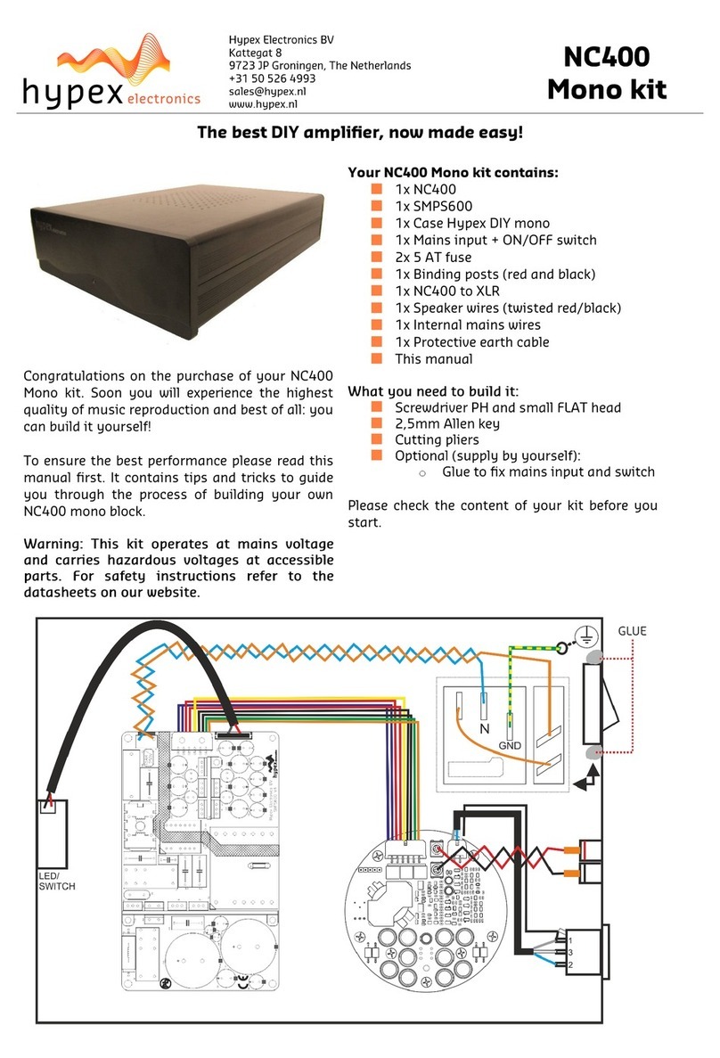
Hypex Electronics NC400 Mono Kit User manual

Hypex Electronics
Hypex Electronics UcD700 User manual