HySecurity SlideDriver 15 User manual

Installation Manual for HyNet Attachment Kit: MX3865
SlideDriver 15, 40, 30F, 80, 200
SlideDriver 50 VF series
StrongArm (HTG)
This document is a supplemental document that provides specic information regarding
conguration of the HySecurity gate operator with installation and wiring of the HyNet Gateway.
For safety considerations and information specic to your gate operator, refer to the HySecurity
gate operator product manuals.

HyNet Components
LED Indicators
Drawing is not to scale
Height
1¼ inches
SFP Module
(100/1000/2500)
Managed Switch
RJ-45 Integration Hub
4-Port Copper Gigabit
(100/1000/2500)
Micro USB
Reset Button
RS-485
USB OTG
Micro SD Card Slot
Mounting Plate
4 x 7½ inches
LED (position 1)
Table 1: HyNet LED Indicators
LED Position LED Color Indicates
1RED ashing No communication from gate operator to HyNet.
1Green steady Communication is established between gate operator and HyNet.
2RED steady Gate operator network communication is not congured or established.
2RED ashing HyNet is attempting to connect to network (web interface).
2GREEN ashing Network (web interface) is established and working. (May not be wholly
congured, yet. Verify conguration with your IT administrator.)
3RED steady Hardware fault.
3RED ashing Charge is low on coin battery. Replace coin battery.
3GREEN steady Hardware functioning and coin battery charged.
4Red steady or no LED lit HyNet internal switch is not functioning.
4GREEN steady HyNet internal switch is functioning.
4321

Velcro strip
Peel off protective layer and adhere
Velcro®strip to HyNet mounting plate.
HyNet Rain Shield
HyNet mounting plate screws (4x)
HyNet Assembly for SlideDriver and StrongArm
Alcohol wipe
Use alcohol wipe to clean
mounting plate surface before
applying Velcro®adhesive backing.
Velcro®strip
Adhere to gate operator
chassis.
HyNet Assembly
HyNet mounting plate
Tools Required
•Phillips head screwdriver

Mount HyNet Assembly to SlideDriver
Loosen two base screws and
lift SlideDriver chassis cover.
Set it aside.
1
2Peel protective paper off
Velcro®strip.
3Adhere the Velcro®strip to the inside
portion of the SlideDriver chassis.
Press rmly.
NOTE: Recommended HyNet
location is shown in the illustration.
Ambient temperature for adhesion is
between 45˚ and 85˚ F.
4Set the HyNet onto the
chassis so the ports are
accessible as shown in the
illustration.
5Press rmly to engage the
Velcro®loops and hooks.
6Connect wiring.
See page 6.
7Replace SlideDriver chassis
cover and secure gate
operator.
Tools Required
•Phillips head screwdriver

Mount HyNet Assembly to StrongArm (HTG)
Lift StrongArm chassis cover
and set it aside.
1
2Peel protective paper off
Velcro®strip.
NOTE: If necessary,
use the key to unlock
the StrongArm door
panel.
3Adhere the Velcro®strip to the top
shelf inside of the StrongArm chassis.
Press rmly.
NOTE: Recommended HyNet
location is shown in the illustration.
Ambient temperature for adhesion is
between 45˚ and 85˚ F.
4Set the HyNet onto the chassis
shelf so the ports are accessible
as shown in the illustration.
5Press rmly to engage the
Velcro®loops and hooks.
6Connect wiring.
See page 6.
Door panel
7Replace chassis cover
and secure gate operator.

HyNet Gateway
Pin 1, COM
Installer supplied
shielded cable
STOP BUTTON
OPEN BUTTON
CLOSE BUTTON
REMOTE OPEN AND
RADIO CONTROL
OPEN/CLOSE
1
OPEN PARTIAL
INTERLOCK OPEN
TIME CLOCK OPEN
FREE EXIT DETECTOR
DISABLE EXIT DETECTOR
DISABLE CLOSE TIMER
INSIDE OBSTRUCTION
VEHICLE DETECTOR
OUTSIDE OBSTRUCTION
VEHICLE DETECTOR
SHADOW/RESET
VEHICLE DETECTOR
SENSOR 1
SENSOR COM
DO NOT USE
DO NOT USE
DO NOT USE
CHARGER
AC LOSS
LOCK INTERLOCK
EMERG CLOSE
FIRE DEPT OPEN
2
3
4
5
6
7
8
9
10
11
12
14
15
16
17
18
19
20
21
22
23
24
Smart Touch Controller
LIMIT DUAL GATE RADIO OPTIONS
DRIVE POWER RS485
MOTOR USER 1 USER 2
USER 3
VEHICLE DETECTORVEHICLE DETECTORVEHICLE DETECTOR
STOP/BUZZER
FREE
EXIT
INSIDE
OBSTR
OUTSIDE
OBSTR
SHADOW
RESET
WIEGAND
HySecurity
COM
NO
MX000585
VERSION
S/N
RS232
DISPLAY
VEHICLE DETECTOR
COM COMA B
RPM
COMOPEN S 1+24V +24V
STAT US
LED
24V AC Accessory power
+
2
4V D
C
COMMON
+ 24VDC
Inputs
SENSOR 2
SENSOR 3
Pin 1, +24V
DO NOT connect to +24V tabs at base of
Smart Touch Controller. Only use the +24V
connections on the Power Supply Board.
CAUTION
NOTE: More detailed wiring information
is shipped with the HyNet.
+24VDC Accessory Power (+)
Drawing is not to scale.
Attach shielded cable
to wire harness.*
2
1Attach to RS-485
port on HyNet.
3Connect to RS-485 port on
Smart Touch Controller.
4Connect ying
lead to +24VDC.
Tact
button
Wire harness
(supplied in box)
5
Supply RJ-45 network
connection
HyNet
RS-485
port
Smart Touch Controller
RS-485
Connector
Common Bus (-)
RS-485 Connector
RS-485 ports
Power Supply Board
*Measure distance between
HyNet and Controller
connections for appropriate
shielded cable length.

STOP BUTTON
OPEN BUTTON
CLOSE BUTTON
REMOTE OPEN AND
RADIO CONTROL
OPEN/CLOSE
1
OPEN PARTIAL
INTERLOCK OPEN
TIME CLOCK OPEN
FREE EXIT DETECTOR
DISABLE EXIT DETECTOR
DISABLE CLOSE TIMER
INSIDE OBSTRUCTION
VEHICLE DETECTOR
OUTSIDE OBSTRUCTION
VEHICLE DETECTOR
SHADOW/RESET
VEHICLE DETECTOR
SENSOR 1
SENSOR COM
DO NOT USE
DO NOT USE
DO NOT USE
CHARGER
AC LOSS
LOCK INTERLOCK
EMERG CLOSE
FIRE DEPT OPEN
2
3
4
5
6
7
8
9
10
11
12
14
15
16
17
18
19
20
21
22
23
24
Smart Touch Controller
LIMIT DUAL GATE RADIO OPTIONS
DRIVE POWER RS485
MOTOR USER 1 USER 2
USER 3
VEHICLE DETECTORVEHICLE DETECTORVEHICLE DETECTOR
STOP/BUZZER
FREE
EXIT
INSIDE
OBSTR
OUTSIDE
OBSTR
SHADOW
RESET
WIEGAND
HySecurity
COM
NO
MX000585
VERSION
S/N
RS232
DISPLAY
VEHICLE DETECTOR
COM COMA B
RPM
COMOPEN S 1+24V +24V
STAT US
LED
24V AC Accessory power
+
2
4V D
C
COMMON
+ 24VDC
Inputs
SENSOR 2
SENSOR 3
Smart Touch Controller
RS-485
Connector
Menu
button
Select
button
Reset
button
Open
button
SA 1
SYSTEM ADDRESS
Press Select again to set gate operator's system
address (Each gate operator attached to the
same HyNet must have a unique SA number.
Choose 1, 2, 3, or 4.)
2
1To access Installer Menu, press Menu button
twice. Then, press Reset and Open.
Press Select to navigate to Installer Menu item
"SA" System Address.
3To exit Menu mode, press Menu. The gate
operator returns to Run mode.
4Refer to Table 1: HyNet LED Indicators on page
2. Solid green means serial communication
is active and functioning well.
HySecurity gate operators provides a 2-wire, serial interface (RS-485 connection) which allows remote access to
one or more operators.
When the physical connection is made and protocols are established, an SA (System Address) must be assigned
for each operator through its Installer Menu.
For network communication, choosing a “SA” of 1 to 4 establishes individual network polling addresses. HyNet
only utilizes numbers 1, 2, 3, or 4.
A “SA” of zero means no network communication is desired.
5For IP network setup, refer to the HyNet Quick
Start manual supplied in the HyNet box..
Power Supply Board
Tact
button
+24VDC Accessory Power (+)
Common Bus (-)

Installer’sCheCklIst
Date Installed: ________________ Gate Operator Model: _________________________________________________________________
Site Location:__________________________________________________________________________________________________________
HyNet Serial Number:___________________________________
Gate Operator Serial Number: ___________________________
Customer Name:_______________________________________________________________________________________________________
Mailing Address:________________________________________ Inspected by: ____________________________________________
________________________________________________________ Date Inspected: __________________________________________
Phone Contact: _________________________________________ Phone contact number: ___________________________________
Checked Initials
1. Site Planning _____________
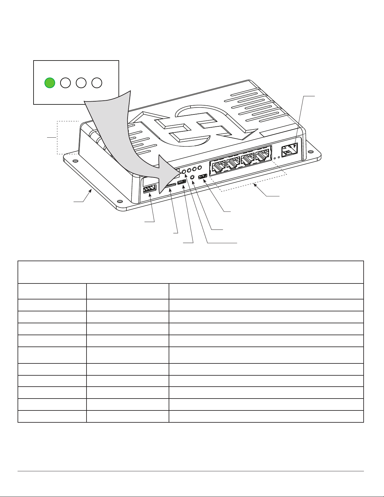
RJ-45 cable to system network.
2. Safety _____________
Review Important Safety Information in the gate operator's product manual.
Warning labels apparent and afxed properly.
Area around gate and gate operator free of debris, cabinets/chassis include locking mechanism.
3. Electrical _____________
3.1 Grounding
• NFPA 780 Standard for the Installation of Lighting Protection Systems.
• Solid copper ground rod (C\,-inch diameter, 10 ft length) driven into ground within 3 ft of the gate operator.
• Single length of unspliced 6AWG copper wire less than 3 ft long attached to lug nut in gate operator.
3.2 Gate operator has current software loaded.
3.3 Congure the Controller
• Set the System Address (SA) in the Installer Menu.
•Communicate (verify) system address to IT Network Admin for proper web page conguration.
4. Review gate operator installation checklist from gate operator manual _____________
5. Take photographs of installation and provide an End User Demo _____________
Other manuals for SlideDriver 15
4
This manual suits for next models
5
Table of contents
Other HySecurity Gateway manuals
Popular Gateway manuals by other brands

Panasonic
Panasonic KX-TDA0480 Getting started

Viessmann
Viessmann Vitogate 300 Installation and service instructions for contractors

IKEA
IKEA tradfri manual

Grandstream Networks
Grandstream Networks GXW4500 Series Quick installation guide

ABB
ABB COM 610 *2.1 user guide

Cisco
Cisco IG21 Series installation guide