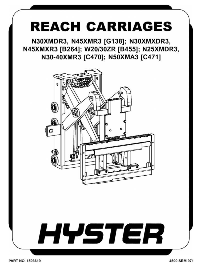
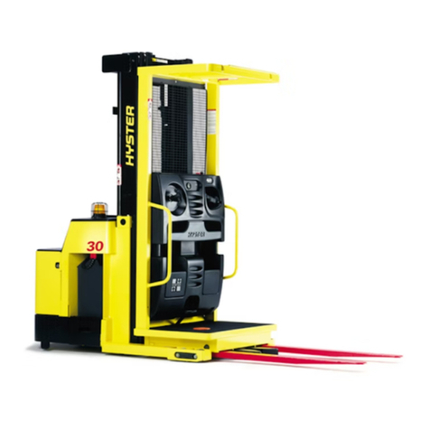
Hyster C471 User manual

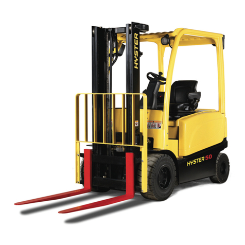
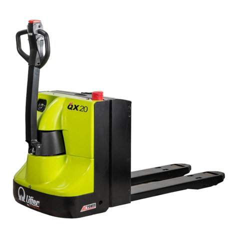
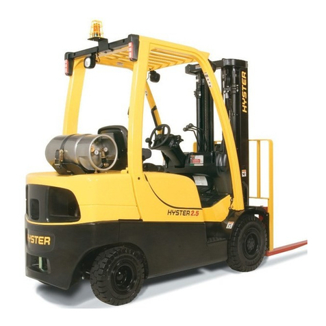
Hyster C471 (N50XMA3) Forklift

PERIODIC
MAINTENANCE
N25XMDR3, N30/40XMR3 [C470];
N50XMA3 [C471];
N30XMDR3, N45XMR3 [G138];
N30XMXDR3, N45XMXR3 [B264]
PART NO. 1487042 8000 SRM 970

SAFETY PRECAUTIONS
MAINTENANCE AND REPAIR
•When lifting parts or assemblies, make sure all slings, chains, or cables are correctly
fastened, and that the load being lifted is balanced. Make sure the crane, cables, and
chains have the capacity to support the weight of the load.
•Do not lift heavy parts by hand, use a lifting mechanism.
•Wear safety glasses.
•DISCONNECT THE BATTERY CONNECTOR before doing any maintenance or repair
on electric lift trucks.
•Disconnect the battery ground cable on internal combustion lift trucks.
•Always use correct blocks to prevent the unit from rolling or falling. See HOW TO PUT
THE LIFT TRUCK ON BLOCKS in the Operating Manual or the Periodic Mainte-
nance section.
•Keep the unit clean and the working area clean and orderly.
•Use the correct tools for the job.
•Keep the tools clean and in good condition.
•Always use HYSTER APPROVED parts when making repairs. Replacement parts
must meet or exceed the specifications of the original equipment manufacturer.
•Make sure all nuts, bolts, snap rings, and other fastening devices are removed before
using force to remove parts.
•Always fasten a DO NOT OPERATE tag to the controls of the unit when making repairs,
or if the unit needs repairs.
•Be sure to follow the WARNING and CAUTION notes in the instructions.
•Gasoline, Liquid Petroleum Gas (LPG), Compressed Natural Gas (CNG), and Diesel fuel
are flammable. Be sure to follow the necessary safety precautions when handling these
fuels and when working on these fuel systems.
•Batteries generate flammable gas when they are being charged. Keep fire and sparks
away from the area. Make sure the area is well ventilated.
NOTE: The following symbols and words indicate safety information in this
manual:
WARNING
Indicates a condition that can cause immediate death or injury!
CAUTION
Indicates a condition that can cause property damage!

Periodic Maintenance Table of Contents
TABLE OF CONTENTS
General ............................................................................................................................................................... 1
How to Move Disabled Truck ........................................................................................................................ 1
How to Tow Lift Truck............................................................................................................................... 1
How to Put Lift Truck on Blocks................................................................................................................... 2
How to Raise Load Wheels ....................................................................................................................... 2
How to Raise Steer Wheel......................................................................................................................... 2
Safety Procedures When Working Near Mast.................................................................................................. 3
Maintenance Schedule....................................................................................................................................... 5
Maintenance Procedures Every 8 Hours or Daily............................................................................................ 8
Checks With Key Switch Turned OFF.......................................................................................................... 8
Battery ....................................................................................................................................................... 9
Hydraulic System...................................................................................................................................... 9
Tires and Wheels....................................................................................................................................... 10
Safety Labels ............................................................................................................................................. 11
Overhead Guard........................................................................................................................................ 11
Mast, Forks, and Lift Chains.................................................................................................................... 11
Reach, Tilt, and Sideshift.......................................................................................................................... 13
Forks .......................................................................................................................................................... 13
Remove .................................................................................................................................................. 13
Install..................................................................................................................................................... 13
Lift Chain Adjustments ............................................................................................................................ 14
Check With Key Switch Turned ON ............................................................................................................. 16
Instruments and Controls......................................................................................................................... 16
Lift System Operation............................................................................................................................... 18
Multifunction Control Handle .................................................................................................................. 18
Brake.......................................................................................................................................................... 18
Steering System ........................................................................................................................................ 19
Maintenance Procedures Every 350 Hours or 2 Months ................................................................................. 19
Master Drive Unit ......................................................................................................................................... 19
Brake .............................................................................................................................................................. 20
Hydraulic System .......................................................................................................................................... 20
Articulation Stop Adjustment....................................................................................................................... 20
Adjustment Procedure .............................................................................................................................. 21
Lift System Operation................................................................................................................................... 22
Forks .......................................................................................................................................................... 22
Mast ........................................................................................................................................................... 22
Lift Chains................................................................................................................................................. 22
Other Lubrication.......................................................................................................................................... 22
Electrical Inspection...................................................................................................................................... 22
Fuses .......................................................................................................................................................... 22
Contactors.................................................................................................................................................. 23
Motor Brushes ........................................................................................................................................... 23
Maintenance Procedures Every 2000 Hours or Yearly .................................................................................... 24
Hydraulic System .......................................................................................................................................... 24
Change Hydraulic Oil ............................................................................................................................... 24
Change Hydraulic Oil Filter..................................................................................................................... 25
Check Hydraulic Oil Strainer................................................................................................................... 25
Brakes ............................................................................................................................................................ 25
Maintenance Procedures Every 3000 Hours or Three Years........................................................................... 25
Traction Motor ............................................................................................................................................... 25
Lift and Tilt System Leaks Check..................................................................................................................... 26
©2003 HYSTER COMPANY i

Thanks very much for your reading,
Want to get more information,
Please click here, Then get the complete
manual
NOTE:
If there is no response to click on the link above,
please download the PDF document first, and then
click on it.
Have any questions please write to me:
admin@servicemanualperfect.com

Table of Contents Periodic Maintenance
TABLE OF CONTENTS (Continued)
Lift System..................................................................................................................................................... 26
Tilt System ..................................................................................................................................................... 26
Brakes Adjustment ............................................................................................................................................ 27
Battery Maintenance ......................................................................................................................................... 28
How to Charge Battery.................................................................................................................................. 28
How to Change Battery................................................................................................................................. 29
Tires and Wheels................................................................................................................................................ 32
Drive Tire ....................................................................................................................................................... 32
How to Change Drive Tire............................................................................................................................. 32
Tandem Load Wheels .................................................................................................................................... 33
Single Load Wheel ......................................................................................................................................... 33
Caster Wheels ................................................................................................................................................ 34
Preparation for Storage ..................................................................................................................................... 36
Short-Term Storage (1 to 6 months) ............................................................................................................. 36
Long-Term Storage (6 months or longer) ..................................................................................................... 36
Transporting....................................................................................................................................................... 36
Loading........................................................................................................................................................... 36
Unloading....................................................................................................................................................... 37
Preparation for Use............................................................................................................................................ 37
Preparation After Shipment ......................................................................................................................... 37
Preparation After Storage............................................................................................................................. 37
This section is for the following models:
N25XMDR3, N30/40XMR3 [C470];
N50XMA3 [C471];
N30XMDR3, N45XMR3 [G138];
N30XMXDR3, N45XMXR3 [B264]
ii

8000 SRM 970 General
General
This section contains a Maintenance Schedule and
the instructions for maintenance and inspection.
The Maintenance Schedule has time intervals for in-
spection, lubrication, and maintenance. The time
intervals are based on a normal operation. A nor-
mal operation is considered to be one 8-hour shift
per day in a relatively clean environment on an im-
proved surface. Multiple shifts, dirty operating con-
ditions, etc., will require a reduction in the recom-
mended time periods in the Maintenance Schedule.
WARNING
Do not make repairs or adjustments unless you
have both authorization and training. Repairs
and adjustments that are not correct can make
a dangerous operating condition.
Do not operate a lift truck that needs repairs.
Report the need for repairs to your supervisor
immediately. If repair is necessary, put a DO
NOT OPERATE tag on the control handle. Re-
move the key from the key switch.
Your lift truck dealer has the facilities and trained
personnel to do the maintenance. A complete pro-
gram of inspection, lubrication, and maintenance
will help your lift truck perform efficiently and oper-
ate over a longer period of time.
Some users have service personnel and facilities to do
the items listed in the Maintenance Schedule. Ser-
vice Manuals are available from your lift truck dealer
to help users who do their own maintenance.
Do not make repairs or adjustments unless specifi-
cally authorized to do so.
Put the lift truck on a level surface. Lower the car-
riage and forks, apply the parking brake, and turn
the key switch to OFF. Open the access panels and
inspect for leaks and conditions that are not normal.
Clean any oil spills. Make sure that lint, dust, paper,
and other materials are removed from the compart-
ments.
HOW TO MOVE DISABLED TRUCK
How to Tow Lift Truck
WARNING
Use extra care when moving a lift truck during
the following conditions:
• Brakes do not operate correctly.
• Steering does not operate correctly.
• Tires are damaged.
• Traction conditions are bad.
• The lift truck must be moved on a steep
grade.
If the steering pump motor does not operate,
steering control of the lift truck can be slow.
This can make the control of the lift truck dif-
ficult. If there is no electrical power, steering
can be difficult. Poor traction can cause the
disabled lift truck or towing vehicle to slide.
Steep grades will require additional brake
force to stop the lift truck.
Never carry a disabled lift truck unless the lift
truck MUST be moved and cannot be towed.
The lift truck used to carry the disabled lift
truck MUST have a rated capacity equal to
or greater than the weight of the disabled
lift truck. The capacity must be for a load
center equal to half the width of the disabled
lift truck. See the nameplate of the disabled
lift truck for the approximate total weight.
The forks must extend the full width of the
disabled lift truck. Center the weight of the
disabled lift truck on the forks and be careful
not to damage the under side of the lift truck.
1. The towed lift truck must have an operator.
2. Tow the lift truck slowly.
3. Raise the carriage and forks approximately
30 cm (12 in.) from the surface.
4. If a counterbalanced lift truck is used to tow the
disabled lift truck, that lift truck must have an
equal or larger capacity than the disabled lift
truck. Install an approximate half-capacity load
on the forks of the lift truck that is being used
to tow the disabled lift truck. This half-capacity
load will increase the traction of the lift truck.
Keep the load as low as possible. Do not attempt
to tow a reach truck with another reach truck.
1
General 8000 SRM 970
HOW TO PUT LIFT TRUCK ON BLOCKS
How to Raise Load Wheels
WARNING
The lift truck must be put on blocks for some
types of maintenance and repair. The removal
of the following assemblies will cause large
changes in the center of gravity: mast and load
axle, battery, and the counterweight. When
the lift truck is put on blocks, put additional
blocks under the rear of the frame before re-
moving the mast so the lift truck cannot fall
backward or to the side.
Put the lift truck on blocks only if the surface
is solid, even, and level. Make sure that any
blocks used to support the lift truck are solid,
one-piece units. Put blocks in front and back of
the tires to prevent movement of the lift truck.
NOTE: Some lift trucks have lifting eyes. These lift
points can be used to raise the lift truck so blocks can
be installed.
1. Putblocksoneachside(frontandback)ofthe
steer tires to prevent movement of the lift truck.
SeeFigure1.
2. Use a hydraulic jack under the side of the frame
near the front. Make sure that the jack has a
capacity equal to at least half the weight of the
lift truck. See the Nameplate.
3. Put additional blocks under the frame behind the
drive tires.
How to Raise Steer Wheel
1. Apply the parking brake. Put blocks on both
sides (front and back) of the drive tires to pre-
vent movement of the lift truck. See Figure 1.
2. Use hydraulic jacks to raise the steer tire. Make
sure that the jacks have a capacity of at least 2/3
of the total weight of the lift truck, as shown on
the nameplate.
3. Put the jacks under the rear of the frame to raise
the lift truck. Put blocks under the frame to sup-
port the lift truck.
1. DRIVE AND CASTER WHEELS 2. LOAD WHEELS
Figure 1. Put Lift Trucks on Blocks
2

8000 SRM 970 Safety Procedures When Working Near Mast
Safety Procedures When Working Near Mast
The following procedures must be used when inspect-
ing or working near the mast. Additional precautions
and procedures can be required when repairing or re-
moving the mast.
WARNING
Mast parts are heavy and can move. Distances
between parts are small. Serious injury or
death can result if part of the body is hit by
parts of the mast or the carriage.
• Never put any part of the body into or under
the mast or carriage unless all parts are com-
pletely lowered or a safety chain is installed.
Also make sure that the power is off and the
key is removed. Put a DO NOT OPERATE tag
in the operator’s compartment. Disconnect
the battery on electric lift trucks and put a
tag or lock on the battery connector.
• Be careful of the forks. When the mast is
raised, the forks can be at a height to cause
an injury.
• Do NOT climb on the mast or lift truck at any
time. Usealadderorpersonnellifttowork
on the mast.
• Do NOT use blocks to support the mast weld-
ments nor to restrain their movement.
• Mast repairs require disassembly and re-
moval of parts and can require removal
of the mast or carriage. Follow the repair
procedures in the correct Service Manual
section for the mast.
WHEN WORKING NEAR THE MAST, ALWAYS:
1. Lower the mast and carriage completely. Push
the lift/lower control lever forward and make
sure there is no movement in the mast. Make
sure that all parts of the mast that move are
fully lowered.
OR
2. If parts of the mast must be in raised position,
install a safety chain to restrain the moving parts
of the mast. Connect moving parts to a part that
does not move. Follow these procedures:
a. Put the mast in a vertical position.
b. Raise the mast to align the bottom cross-
member of the weldment that moves in the
outer weldment with a crossmember on the
outer weldment (1). On the two-stage and
free-lift mast, the moving part is the inner
weldment (2). On the three-stage mast, it is
the intermediate weldment (3). See Figure 2.
c. Use a 3/8-in. minimum safety chain with
a hook (4) to fasten the crossmembers to-
gether so that the movable member cannot
lower. Put the hook on the back side of the
mast. Make sure the hook is completely en-
gaged with a link in the chain. Make sure
the safety chain does not touch lift chains or
chain sheaves, tubes, hoses, fittings, or other
parts on the mast.
d. Lower the mast until there is tension in
the safety chain, and the free-lift cylinder
(5) (free-lift and three-stage masts) is com-
pletely retracted. If the engine is running,
stop the engine. Apply the parking brake.
Install a DO NOT REMOVE tag on the
safety chain(s).
e. Install another safety chain (3/8 in. mini-
mum) between the top or bottom crossmem-
ber (6) of the carriage and a crossmember (7)
on the outer weldment.
3. Apply the parking brake. After lowering or re-
straining the mast, shut off the power and re-
move the key. Put a DO NOT OPERATE tag in
the operator’s compartment. Disconnect the bat-
tery on electric lift trucks and put a tag or lock
on the battery connector.
3

Safety Procedures When Working Near Mast 8000 SRM 970
A. TWO-STAGE MAST B. THREE-STAGE MAST
1. OUTER WELDMENT
2. INNER WELDMENT
3. INTERMEDIATE WELDMENT
4. HOOK
5. FREE-LIFT CYLINDER
6. CROSSMEMBER
7. CROSSMEMBER
Figure 2. Two-Stage and Three-Stage Masts
4

8000 SRM 970 Maintenance Schedule
Maintenance Schedule
The Maintenance Schedule has two time periods in
which the service technician can perform the main-
tenance. For lift trucks operated less than 8 hours
each day, use the 1-DAY, 2-MONTH, and 1-YEAR
period schedule. For lift trucks operated more than
8 hours each day, use the 8-HOUR, 350-HOUR, and
2000-HOUR schedule.
Figure 3. Maintenance Points
5

Maintenance Schedule 8000 SRM 970
Table 1. Maintenance Schedule
Item
No. Item 8hr/
1day
4350 hr/
2mo
42000
hr/
1yr
4
Procedure or
Quantity Specification
Battery X5Check Level See Specifications
Restraint Panels XCheck Condition
1
Power Disconnect XCheck Operation
Brake XCheck Operation
Fluid X0.45 liter
(0.12 gal) SAE J-1703 Brake
Fluid
Rods and Drum Splines LAs Required Antiseize Lubricant3
2
Master Cylinder CDrain, Flush, Fill SAE J-1703 Brake
Fluid
3Control Handle XCheck Operation
Electrical Circuits XCheck Operation
Contactors XCheck Condition
Motor Brushes XCheck Condition
4
Traction Motor X,C84 Bearings
Seal
Forks-All XCheck for Damage
5
Hook Fork Guides and Locks X L As Required Antiseize Lubricant3
6Gauges, Horn, Lights, Fuses XCheck Operation
Hydraulic Oil Leaks XCheck for Leaks
Hydraulic Oil Level (Full Mark) X C 18 liter (4.75 gal) Above 0 C(32F)1
Below 0 C2
Dipstick/Breather Cap XClean or Replace
Hydraulic Oil Filter CReplace See Parts Manual
7
Hydraulic Oil Strainer CClean or Replace See Parts Manual
X=Check C=Change L=Lubricate
1Hydraulic Oil
2Chevron EP Hydraulic Oil 68 or equivalent
3Antiseize Lubricant
4Whichever comes first
5Equalization Charge approximately each month but not more than each week
6Multipurpose Grease with 2-4% Molybdenum Disulfide for normal operations
7Change after 150 to 500 hours. No subsequent change for life of unit
8Change every 3000 hours or 3 years
6

8000 SRM 970 Maintenance Schedule
Table 1. Maintenance Schedule (Continued)
Item
No. Item 8hr/
1day
4350 hr/
2mo
42000
hr/
1yr
4
Procedure or
Quantity Specification
Lift Chains X L Check for Damage Engine Oil
8
Articulating Chain Anchors
-3-StageMast L2 Lube Fittings Multipurpose Grease6
Mast and Carriage XCheck Operation
9
Pivots, Sliding Surfaces L6As Required Multipurpose Grease6
Articulation Shaft L1 Lube Fitting Multipurpose Grease6
Articulation Shaft Retaining Bolt LAntiseize Lubricant3
10
Articulation Shaft Ends LAntiseize Lubricant3
Reach Arms-Single Reach X L 6 Lube Fittings Multipurpose Grease6
Reach Arms-Double Reach L12 Lube Fittings Multipurpose Grease6
Reach Cylinder Pivot Pins L4 Lube Fittings Multipurpose Grease6
11
Thrust Rollers-Reach Frame L2 Lube Fittings Multipurpose Grease6
12 Pedals, Levers, Cables, Hinges,
Linkages LAs Required Antiseize Lubricant3
13 Safety Labels and Operating Man. XReplace if
Necessary See Parts Manual
14 Steering Operation XCheck Operation
Tire and Wheels XCheck Condition
Caster Wheel Assembly X L 4 Lube Fittings Multipurpose Grease6
15
Load Wheel Bolts LAntiseize Lubricant3
X=Check C=Change L=Lubricate
1Hydraulic Oil
2Chevron EP Hydraulic Oil 68 or equivalent
3Antiseize Lubricant
4Whichever comes first
5Equalization Charge approximately each month but not more than each week
6Multipurpose Grease with 2-4% Molybdenum Disulfide for normal operations
7Change after 150 to 500 hours. No subsequent change for life of unit
8Change every 3000 hours or 3 years
7

Maintenance Procedures Every 8 Hours or Daily 8000 SRM 970
Table 1. Maintenance Schedule (Continued)
Item
No. Item 8hr/
1day
4350 hr/
2mo
42000
hr/
1yr
4
Procedure or
Quantity Specification
Master Drive Unit Bearing L2 Lube Fittings Multipurpose Grease6
Master Drive Unit Chain LApply to Chain Multipurpose Grease6
Master Drive Unit
Small trucks, HFK 300 BF
Large trucks, ZF 400 SF
X, C70.66 liter
(0.17 gal) SAE 80W-90 or
Mobilgear 627
Master Drive Unit
Small trucks, GK - 20
Large trucks, GK - 25
X, C70.98 liter
(0.26 gal) SAE 80W-90 or
Mobilgear 627
Articulation Adjustment Stops X, L Antiseize Lubricant3
16
Adjustment Stop Retaining Bolt LAdjust Antiseize Lubricant3
Wheel Bolt Torque XTighten if
Required 135 N•m (100 lbf ft)
17
Drive Wheel Lugs LAntiseize Lubricant3
X=Check C=Change L=Lubricate
1Hydraulic Oil
2Chevron EP Hydraulic Oil 68 or equivalent
3Antiseize Lubricant
4Whichever comes first
5Equalization Charge approximately each month but not more than each week
6Multipurpose Grease with 2-4% Molybdenum Disulfide for normal operations
7Change after 150 to 500 hours. No subsequent change for life of unit
8Change every 3000 hours or 3 years
Maintenance Procedures Every 8 Hours or Daily
WARNING
Do not operate a lift truck that needs repairs.
If a repair is necessary, put a DO NOT OPER-
ATE tag in the operator’s area. Remove the key
from the key switch.
Inspect the lift truck every 8 hours or daily before
use. Put the lift truck on a level surface. Lower the
carriage and forks, and turn the key switch to OFF.
If repair is required, put a tag in the operator’s area
that indicates the lift truck cannot be operated. DO
NOT operate a lift truck until the problems are cor-
rected.
CHECKS WITH KEY SWITCH TURNED OFF
Make the following checks:
•Electrolyte and specific gravity of the battery
•Make sure the battery is clean and the correct size
and weight for the lift truck
•Check that the battery restraint plates are in place
•Oil level in the hydraulic tank
•Leaks in the hydraulic system
•Condition of the wheels and tires
•Condition of the forks, carriage, mast, and over-
head guard
8

8000 SRM 970 Maintenance Procedures Every 8 Hours or Daily
Battery
WARNING
Do not put tools on the battery.
The acid in the electrolyte can cause injury. If
the electrolyte is spilled, use water to flush the
area. Make the acid neutral with a solution
of sodium bicarbonate (soda). Acid in the eyes
must be flushed with water immediately.
Batteries generate explosive fumes. Keep the
vents in the caps clean. Keep sparks or open
flames away from the battery area. Do not
make a spark from the battery connections.
Disconnect the battery when doing mainte-
nance.
The battery must fit the battery compartment
so the battery restraint panels will operate cor-
rectly. Use spacers to prevent the battery from
moving more than 13 mm (0.5 in.) in any direc-
tion.
CAUTION
Disposal of batteries must meet local environ-
mental regulations.
Make sure the battery weight is within the maximum
and minimum weight shown on the nameplate.
Keep the battery case, top cover, and the area for the
battery clean and painted. Leakage and corrosion
from the battery can cause a malfunction in the elec-
tric controls of the lift truck. Use a water and sodium
bicarbonate solution (soda) to clean the battery and
the battery area. Keep the top of the battery clean,
dry, and free of corrosion.
Make sure the battery is charged and has the correct
voltage and ampere hour rating for the lift truck. See
the nameplate.
Inspect the battery case, connector, and cables for
damage, cracks, or breaks. See the battery dealer
in the area to repair any damage. Check the level of
the electrolyte daily on a minimum of one cell. The
correct level is halfway between the top of the plates
and the bottom of the fill hole. Add only distilled
water.
Make certain the battery restraint panels are prop-
erly installed.
WARNING
Make sure the key switch is OFF and the brake
is set before connecting the battery.
If the lift truck was operated with a discharged
battery, check all contactors for welded tips be-
fore a charged battery is connected.
The battery should have an equalization charge each
month, but not more than each week.
Hydraulic System
WARNING
At operating temperature, the hydraulic oil is
HOT. Do not permit the oil to contact the skin
and cause a burn.
CAUTION
Do not permit dirt to enter the hydraulic sys-
tem when the oil level is checked or the filter
is changed.
Never operate the pump without oil in the hy-
draulic system. The operation of the hydraulic
pump without oil will damage the pump.
Check the hydraulic oil level when the oil is at oper-
ating temperature, the carriage is lowered, the reach
mechanism is retracted, and the key switch is in the
OFF position. See Figure 4. Add hydraulic oil only
as needed. If more hydraulic oil is added than the
FULL level on the dipstick, hydraulic oil will leak
from the breather during operation. See Table 4 for
the capacities of the hydraulic tanks used on these
models of lift trucks.
Inspect the hydraulic system for leaks and damaged
or loose components.
9

Maintenance Procedures Every 8 Hours or Daily 8000 SRM 970
1. BREATHER
2. DIPSTICK/FILLER CAP
3. TANK
4. STEERING CONTROL UNIT
5. CONTROL VALVE
6. STEERING PUMP AND MOTOR
7. FILTER
8. LIFT PUMP AND MOTOR
Figure 4. Typical Hydraulic System
Tires and Wheels
CAUTION
When the wheels have been installed, check
all wheel nuts after 2 to 5 hours of operation.
Tighten the nuts in a cross pattern to the cor-
rect torque value shown in the Maintenance
Schedule, Table 1. When the nuts stay tight af-
teran8-hourcheck,theintervalforchecking
the torque can be extended to 350 hours.
Inspect the tires for wire, rocks, glass, pieces of
metal, holes, cuts, and other damage. See Figure 5.
Removeanyobjectthatwillcausedamage. Check
for loose or missing hardware. Remove any wire
strapping or other material that is wrapped around
the axle. Make sure the drive wheel nuts are tight.
Tighten the drive wheel nuts in a cross pattern to
the correct torque value shown in the Maintenance
Schedule, Table 1.
10

8000 SRM 970 Maintenance Procedures Every 8 Hours or Daily
1. CHECK FOR DAMAGE. REMOVE NAILS, GLASS,
METAL, AND OTHER OBJECTS.
2. MAKE EDGES SMOOTH
Figure 5. Check Tires
Safety Labels
WARNING
Safety labels are installed on the lift truck to
give information about possible hazards. It is
important that all safety labels are installed on
the lift truck and can be read.
Check that all safety labels are installed in the cor-
rect locations on the lift truck. See the Parts Man-
ual or the Frame 100 SRM 975 for the correct loca-
tions of the safety labels.
Overhead Guard
WARNING
Do not operate the lift truck without the over-
head guard correctly fastened to the lift truck.
Do not make changes to the overhead guard by
welding. Changes that are made by welding or
by drilling holes that are too big in the wrong
location can reduce the strength of the over-
head guard.
Do not weld mounts for lights or accessories to
the legs of the overhead guard. The strength of
the overhead guard can be reduced by welding
or heating.
WARNING
Make sure the capscrew that holds the vertical
post that supports the overhead guard is in the
correct position and is tight. The capscrew al-
lows the support post to provide protection to
the operator ifthetruckhitsarack.
Make certain the overhead guard is in place and se-
curely attached to the body of the lift truck. Make
certain that the mast guard is installed between the
mast and the operator’s compartment.
Mast, Forks, and Lift Chains
WARNING
When working on or near the mast or carriage,
see Safety Procedures When Working Near
Mast.
The identification of a fork describes how the fork is
connected to the carriage. These lift trucks can have
hook type forks.
Adjust the forks as far apart as possible for maximum
support of the load. Hook forks are connected to the
carriage by hooks and lock pins. These lock pins are
installed through the top fork hooks and fit into slots
in the top carriage bar. Raise the lock pin in each fork
toslidetheforkonthecarriagebar. Makesurethe
lock pin is engaged to lock the fork in position after
making adjustments.
WARNING
Do not try to correct fork tip alignment by
bending the forks or adding shims. Never
repair damaged forks by heating or welding.
Forks are made of special steel using special
procedures. Replace damaged forks.
1. Inspect the welds on the mast and carriage for
cracks. Make sure the nuts and capscrews are
tight.
2. Inspect the channel for excessive wear in the ar-
eas of roller contact. Check the rollers for wear
or damage.
11

Maintenance Procedures Every 8 Hours or Daily 8000 SRM 970
3. Inspect the forks for cracks and wear. Check that
the fork tips are aligned within 3% of the length
of the fork of each other [40 mm (1.6 in.) for a
1220 mm (48 in.) fork]. Some applications can re-
quire closer alignment. Check that the bottom of
the fork is not worn (5, Figure 6). Check the heel
of the fork using fork tool. The heel of the fork
must be 90% of DIMENSION X. See Figure 6.
4. Replace any damaged or broken parts that are
used to keep the forks locked in position.
5. If the lift truck is equipped with a sideshift car-
riage or attachment, inspect the parts for cracks
and wear. See Reach, Tilt, and Sideshift.
6. Check that the lift chains are correctly lubri-
cated.
7. Inspect the lift chains for cracks or broken links
and pins.
8. Inspect the chain anchors and pins for cracks and
damage.
9. Make sure the lift chains are adjusted so they
have equal tension. If the chains need to be re-
placed or adjusted, it must be done by authorized
personnel.
Fork Tip Alignment
Length of Forks 3% Dimension
0914 mm (36 in.)
1067 mm (42 in.)
1220 mm (48 in.)
1371 mm (54 in.)
1524 mm (60 in.)
27 mm (1.08 in.)
32 mm (1.26 in.)
37 mm (1.44 in.)
41 mm (1.62 in.)
46 mm (1.80 in.)
1. TIP ALIGNMENT (MUST BE WITHIN 3% OF
FORK LENGTH)
2. CRACKS
3. LATCH DAMAGE
4. HEEL OF FORK (MUST BE 90% OF
DIMENSION X)
5. HEEL WEAR
6. FORK TOOL
Figure 6. Check the Forks
12

8000 SRM 970 Maintenance Procedures Every 8 Hours or Daily
Reach, Tilt, and Sideshift
WARNING
Make sure the key switch is in the OFF position
and the key is removed from the switch before
doing this check.
1. Check for cracks at the welds on the reach frames
and scissor arms.
2. Check the frame channel for excessive wear in
the areas of roller contact. Check the rollers for
wear or damage.
3. Check the load backrest extension for cracks and
damage. Make sure the nuts and bolts for the
load backrest extension are tight.
Forks
Remove
WARNING
Do not try to move a fork without a lifting de-
vice. Each hook fork for these lift trucks can
weigh 45 to 115 kg (100 to 253 lb).
Hook Forks -Slideahookforktotheforkremoval
notch on the carriage. See Figure 7 and Figure 8.
Lower the fork onto blocks so the bottom hook of the
fork moves through the fork removal notch. Lower
thecarriagefurthersothetophookoftheforkisdis-
engaged from the top carriage bar. Move the carriage
away from the fork, or use a lifting device to move the
fork away from the carriage.
Install
WARNING
Do not try to move a fork without a lifting de-
vice. Each hook fork for these lift trucks can
weigh 45 to 115 kg (100 to 250 lb).
Hook Forks -Movetheforkandcarriagesothetop
hook on the fork can engage the top carriage bar.
Raisethecarriagetomovethelowerhookthrough
the fork removal notch. Slide the fork on the carriage
so both upper and lower hooks engage the carriage.
Engage the lock pin with a notch in the top carriage
bar.
1. LATCH ASSEMBLY
2. LEVER
3. ROLL PIN
4. WASHER
5. SPRING
6. LATCH PIN
7. FORK
Figure 7. Hook Fork
1. CARRIAGE BARS
2. HOOK FORK 3. BLOCKS
Figure 8. Hook Fork Removal
13

Maintenance Procedures Every 8 Hours or Daily 8000 SRM 970
Lift Chain Adjustments
When correctly adjusted (see Figure 9):
•Thetensionwillbethesameoneachchainofthe
chain set. Check tension by pushing on both chains
at the same time.
•The chain length will be correct.
•The chains must travel freely through the complete
cycle.
1. CARRIAGE ROLLER
2. FORK
3. CARRIAGE ROLLER MUST NOT EXTEND
MORE THAN 34 mm (1.3 in.) BELOW THE MAST
CHANNEL
Figure 9. Lift Chain Adjustments
1. Put a load equal to 80 to 90% of the capacity load
on the forks. Lower the forks as much as possi-
ble.
2. Check the amount that the bottom carriage roller
extends below the inner channel of the mast. The
carriage roller must not extend more than 1/3 of
the roller diameter below the inner channel. If
the adjustment is not correct, adjust the chain
anchors. Make sure each chain anchor is ad-
justed the same amount.
3. Remove the load from the forks. Check the clear-
ance of the carriage when the mast is fully ex-
tended. The carriage stops must not touch the
stop on the top crossmember of the inner weld-
ment. The chains are too tight if the carriage
touches the crossmember. Lower the carriage
completely. If the forks do not just touch the sur-
face, the chains are too tight. If the chains are
too tight, adjust the chain anchors. Make sure
each anchor is adjusted the same amount.
NOTE: When the chain adjustments are complete,
make sure the threads on the nuts of the chain an-
chors are completely engaged. Make sure the nuts
on the chain anchors are not tight against the mount-
ings. The chain anchors must be free to move in their
sockets.
4. Three-stage mast chain adjustment: Adjust the
main lift chains so the top of the inner weld-
ment is even with the top of the intermediate
weldment within ±1.5 mm (0.06 in.). Adjust the
free-lift chain as described in Step 3.
5. If a section of chain is 3% longer than a similar
section of new chain, the chain is worn and must
be replaced. If a chain scale is available, check
the lift chains as shown in Figure 10. If a chain
scale is not available, measure 20 links of chain.
Measure from the center of a pin to the center of
another pin 20 pitches away. Compare the length
with the chart in Figure 10. Replace the chain if
the length of 20 links of the worn section is more
than the maximum wear limit.
14
Table of contents
Other Hyster Forklift manuals

Hyster
Hyster C024 User manual

Hyster
Hyster S40XM Manual

Hyster
Hyster H1.5XT User manual

Hyster
Hyster Narrow Aisle N30XMR3 User manual

Hyster
Hyster R30XMF3 User manual

Hyster
Hyster S30FT User manual

Hyster
Hyster F003 Operating instructions

Hyster
Hyster J40-65Z Guide

Hyster
Hyster A276 Programming manual

Hyster
Hyster H70XM User manual

Hyster
Hyster H4.0FT5 Operating instructions

Hyster
Hyster T5Z Manual

Hyster
Hyster E004 Operating instructions

Hyster
Hyster W40Z User manual

Hyster
Hyster K007 User manual

Hyster
Hyster B460 K1.0M User manual

Hyster
Hyster A214 User manual

Hyster
Hyster A214 Operating instructions

Hyster
Hyster A244 Operating instructions

Hyster
Hyster A380 User manual