HYT TM-800K User manual


Contents
Introduction …………………………………………………………………………………… 1
Safety Information …………………………………………………………………………… 1
Radio Overview ……………………………………………………………………………… 3
Software Specifications …………………………………………………………………… 6
Circuit Description ………………………………………………………………………… 16
Semiconductor Data ……………………………………………………………………… 21
TM-800K Parts List 1 ……………………………………………………………………… 28
Tuning Description ………………………………………………………………………… 77
Terminal Function ………………………………………………………………………… 89
Troubleshooting Flow Chart ……………………………………………………………… 92
Disassembly and Assembly for Repair ………………………………………………… 96
Exploded View ……………………………………………………………………………… 98
TM-800K Parts List 2 ……………………………………………………………………… 99
Packing ……………………………………………………………………………………… 100
Specifications ……………………………………………………………………………… 123
Appendix 1 Entering Characters ……………………………………………………… 124

TM-800K Service Manual
1
Introduction
Manual Scope
This manual is intended for use by experienced technicians familiar with similar types of
communication equipment. It contains all service information required for the equipment and is current
as of the publication date.
Safety Information
The following safety precautions shall always be observed during operation, service and repair of this
equipment.
zThis equipment shall be serviced by qualified technicians only.
zDo not modify the radio for any reason.
zUse only HYT supplied or approved antenna.
zGain of antenna must not exceed 3dBi for VHF or 5.5dBi for UHF.
zMobile antenna Installation: Install the mobile antenna at least 82cm (32 inches) away from your
body, in accordance with the requirements of the antenna manufacturer/supplier.
zTransmit only when people inside and outside the vehicle are at least the minimum distance away
from a properly installed, externally mounted antenna.
zMobile antenna substitution: Don’t substitute HYT supplied or approved antenna, or excessive
radio frequency radiation will result. Please contact your dealer or the manufacturer for further
instructions.
zPlease make sure there’s no stress on the antenna joint during transportation or installation.
zTo avoid electromagnetic interference and/or compatibility conflicts, turn off your radio in any area
where posted notices instruct you to do so. Hospital or health facilities may be using equipment
that is sensitive to external RF energy.
zFor vehicles with an air bag, do not place a radio in the area over an air bag or in the air bag
deployment area.
zTurn off your radio prior to entering any area with explosive and flammable materials.
zDo not expose the radio to direct sunlight over a long time, nor place it close to heating source.

TM-800K Service Manual
2
▇Operation Guidelines
For vehicles equipped with electronic anti-skid braking systems, electronic ignition systems or
electronic fuel injection systems, interferences may occur during radio transmission. If the foregoing
electronic equipments are installed on your vehicle, please contact your dealer for further assistance to
make sure that radio transmission will not interfere with these equipments.
For radio installation in vehicles fueled by LP gas with LP gas container within interior of the vehicles,
the following precautions are recommended for personal safety.
1. Any space containing radio equipment shall be isolated by a seal from the space in which the LP
gas container and its fittings are located.
2. Remote (outside) fitting connections shall be used.
3. Good ventilation is required for the container space.
▇Installation Guidelines
zVehicle installation: The antenna can be mounted at the center of a vehicle metal roof or trunk lid if
the minimum safe distance is observed.
zDo not mount the mobile radio overhead or on a sidewall unless you take special precautions.
zIf the mobile radio is not properly installed, road shock could bump the radio loose, and the falling
radio could, in some circumstances, cause serious injury to the driver or a passenger. In case of
vehicle accidents, even when properly installed, the radio could break loose and become a
dangerous projectile.

TM-800K Service Manual
3
Radio Overview
Front Panel View
1. Programmable Function Keys ( [ PF1 ] through [ PF6 ] )
Your dealer can program these keys as shortcuts to various radio features.
2. Microphone Jack
Plug a 6-pin connector into the jack.
3. Power Switch / Selector Knob
Press the power switch to turn the radio on/off.
The knob may be programmed by your dealer to select Volume Up / Down, Channel Up / Down,
and Zone Up / Down.
Turn the knob clockwise to adjust upwards and counter-clockwise to adjust downwards.
4. LCD Display
Please refer to the section “ LCD Display ”.
5. [ ▲] ( Up ) / [ ▼] ( Down ) Key
The keys may be programmed by your dealer to select Volume Up / Down, Channel Up / Down,
and Zone Up / Down.
6. LED Display
Used to display the operating status of main unit. Please refer to the section of “ LED Display ”.
7. Numeric Keys and Function Keys

TM-800K Service Manual
4
Used when you select channel or transmit selective call etc.
8. Speaker
Used to output audio.
Microphone
LCD Display
Indicator Description
1. Display zone / channel number.
2. Display zone / channel alias ( up to 12 alphanumeric characters ).
3. Display channel frequency
4. Display the preprogrammed function
1. Display zone / channel number.
2. Display transmit power level ( H, M or L ).
3. Display the preprogrammed function.
Appears when the current channel is busy.
Appears when the Monitor key is pressed to monitor channel activities or
during a selective call.
Appears when Monitor key is pressed to unmute the speaker.
AAppears when DTMF Live Dial mode or DTMF Keypad mode is enabled.
SCAN Appears while scanning.
CALL Appears when transmitting a selective call.
Appears when Scrambler is enabled
Appears when Compandor is enabled

TM-800K Service Manual
5
Rear Panel View
1. DB15
Further development interface.
2. DC power jack
Used to connect 13.6V DC power.
3. Fuse of DC power
4. Grounding terminal
5. Switch of AC power
6. Fuse of AC power
7. AC power jack
8. Antenna connector

TM-800K Service Manual
6
Software Specifications
Radio Modes
Frame of Radio Modes
Keypad Entry for Mode Startup
MODE Main Menu Display/Sub Menu Operation Remarks
USER MODE Conventional Mode ------------------------------- Turn on the radio to enter
Conventional Mode
Test Mode -------------------------------
Adjust Mode -------------------------------
TEST &
ADJUST
MODE Model Set Mode -------------------------------
While holding down [ PF2 ] key,
turn on the radio
Firmware Version Display Mode ------------------------------- While holding down [ PF3 ] key,
turn on the radio
Firmware Programming Mode ------------------------------- While holding down [ PF4 ] key,
turn on the radio
Wired Clone Mode ------------------------------- While holding down [ PF5 ] key,
turn on the radio
PC Programming Mode ------------------------------- Receive commands from PC
Note: When power-on password is enabled, you must input the correct password before you can
enter User Mode.
You can input password through the keypad and press [ # ] to clear.
Error Information and Measures in User Mode
The radio self-checks when power on. If no error is detected, the radio enters conventional mode.
While the radio will sound alert once any error is checked.
Firmware Pro
g
rammin
g
Mode
PC Pro
g
rammin
g
Mode
Clone Mode Wired Clone Mode
User Mode Conventional Mode
Model Set Mode
Test & Ad
j
ust Mode

TM-800K Service Manual
7
Error information and measures:
No. Error Information LCD Display Measures
1 Stun status Stun Re-program.
2 Data and Firmware Version
mismatch No Data Re-program with programming software of right
version.
Firmware Programming Mode
The built-in FLASH ROM enables user to add new functions simply by upgrading.
(1) Turn on the radio while holding down [ PF4 ] simultaneously to enter Firmware Programming
Mode, “ PC Program ” appears on the LCD.
(2) Run the programming software.
(3) Connect the radio with a PC by programming cable.
(4) Select the corresponding COM port, and then click “ Download ”.
(5) When data is successfully written into the radio, click “ OK ” to exit.
(6) Repeat step 1 through 5 to program another radio.
Note: The radio can’t enter the Firmware Programming Mode if it is disabled by your dealer.
It can be set ON only after being programmed through the programming software.
Firmware Version Display Mode
Turn the radio on while holding down [ PF3 ] to enter Firmware Version Display Mode, the firmware
version will be displayed on the LCD.
Release [ PF3 ] to enter User Mode.
PC Mode
Connect the radio with a PC by programming cable. If data is written to the radio from PC, it can be
programmed into the FLASH. Data programming is accessible by programming software.
When data is written to the radio from PC, “ PROGRAMMING ” appears on the LCD. LED glows green
when data is written to the radio and red when data is read from the radio. Radio will restart automati-
cally when programming is completed.
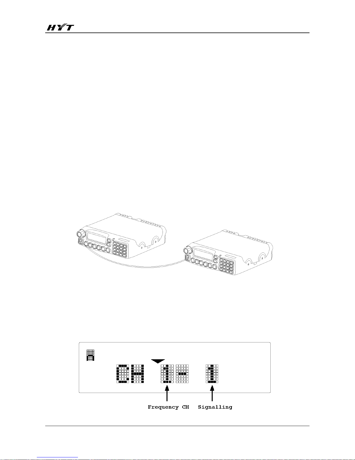
Wired Clone Mode
Data can be transmitted from radio to radio by wired cloning.
(1) Turn on the source radio while holding down [ PF5 ] simultaneously, the radio enters Clone
Mode with “CLONE” on the LCD, or enters User Mode if Clone Mode is disabled by your dealer.

TM-800K Service Manual
8
(2) Press [ PF2 ] to toggle between Dealer Clone and Factory Clone Mode. “Dealer Clone” or
“Factory Clone” appears on the display when the corresponding mode is selected. The radio
restores the original display after 5 seconds.
Unlike Factory Clone Mode, tuning settings and embedded messages are not covered in Dealer
Clone Mode.
Dealer Clone Mode is the default mode.
(3) Connect the two radios by clone cable, and then turn on the target radio.
(4) Press [ PF6 ] to start cloning, the LED of source radio glows red and that of target radio glows
green during cloning. “PROGRAMMING” is also displayed on the target radio. “END” appears on
the source radio when cloning is completed and the target radio displays “END” when all data is
received.
(5) Press [ PF6 ] to return to Clone Mode. “CLONE” appears on the source radio. Repeat the above
steps to continue wired cloning.
Note: Cloning is available only when both radios are in the same mode.
Test Mode
1. Turn the radio on while holding down [ PF2 ], the radio enters Test Mode. Test frequency channel
and signalling test channel are displayed.

TM-800K Service Manual
9
In this mode, the channel frequency ( center, low, high ) can be modified through the programming
software.
Test frequency channels are shown in the following table:
Model RX / TX CH1 ( C ) CH 2 ( L ) CH 3 ( H ) CH 4 CH 5 CH 6 CH 7 CH 8
RX(MHz) 155.15 136.15 173.85 145.55 164.55 155.00 155.20 155.40136-174M
(V) TX(MHz) 155.00 136.00 174.00 145.50 164.50 155.00 155.20 155.40
RX(MHz) 481.15 450.15 511.85 465.55 496.55 481.00 481.20 481.40
450-512M
(U2) TX(MHz) 481.00 450.00 512.00
465.50 496.50 481.00 481.20 481.40
RX(MHz) 375.15 350.15 399.85
362.55 387.55 375.00 375.20 375.40
350-400M
(U5) TX(MHz) 375.00 350.00 400.00
362.50 387.50 375.00 375.20 375.40
RX(MHz) 435.15 400.15 469.85
417.55 452.55 435.00 435.20 435.40
400-470M
(U1) TX(MHz) 435.00 400.00 470.00
417.50 452.50 435.00 435.20 435.40
RX(MHz) 465.15 440.15 489.85 452.55 477.55 465.00 465.20 465.40440-490M
(U4) TX(MHz) 465.00 440.00 490.00 452.50 477.50 465.00 465.20 465.40
RX(MHz) 503.15 480.15 525.85
491.75 515.25 503.00 503.20 503.40
480-526M
(U3) TX(MHz) 503.00 480.00 526.00
491.70 515.20 503.00 503.20 503.40
RX(MHz) 425.15 400.15 449.85 412.55 437.55 425.00 425.20 425.40400-450M
(U6) TX(MHz) 425.00 400.00 450.00 412.50 437.50 425.00 425.20 425.40
RX(MHz) 485.15 450.15 519.85 467.55 502.55 485.00 485.20 485.40450-520M
(U7) TX(MHz) 485.00 450.00 520.00 467.50 502.50 485.00 485.20 485.40
Signallings are shown as follows:
No. RX TX Description
1 None None
2 None 100Hz square wave
3 CTCSS 67.0Hz CTCSS 67.1Hz
4 CTCSS 151.4Hz CTCSS 151.4Hz
5 CTCSS 210.7Hz CTCSS 210.7Hz
6 CTCSS 250.3Hz CTCSS 250.3Hz
7 CDCSS 023N CDCSS 023N
8 CDCSS 754I CDCSS 754I
9 None DTMF (159D)
10 None DTMF 9
11 None 5-Tone ( 037BC ( EEA ) )
12 None Single tone 1200Hz
13 None Single tone 1000Hz
14 None None
2. In Test Mode, the following functions can be accomplished by key press:

TM-800K Service Manual
10
Key Function Description
Up Volume Up
Down Volume down
PF1 Wide/Medium/Narrow band
PF2 Squelch Open / Close “ ” icon appears when squelch is open.
PF3 Test Mode / Adjust Mode
PF4 Activate compandor function
PF1: enable / disable compandor
PF2: enable / disable clock shift
PF3: 1200 / 2400bps MSK
PF5 Signalling Up
PF6 Signalling Down
Selector Knob Channel Up/Down
In Test Mode, press [ PF4 ], then press the following key to enable the corresponding functions.
PF1 Enable / disable Compandor “ ▼” icon appears when compandor is enabled
PF2 Enable / disable Clock Shift “ A ” icon appears when clock shift is enabled
PF3 1200 / 2400bps MSK “ ” icon appears when 2400bps is selected
PF4 Return to Test Mode
PF5 None
PF6 None
3. In Test Mode, press [ PF3 ] to enter Adjust Mode. Turn the Selector Knob to choose your desired
setting items.
No. Adjust Item LCD Display
1 Frequency stability Frequency
2 TX power Tx Power
3 Max. deviation Max.Deviate
4 CDCSS balance CDCSSBalance
5 CTCSS deviation CTCSSDeviate
6 CDCSS deviation CDCSSDeviate
7 DTMF deviation DTMFDeviate
8 MSK deviation MSK Deviate
9 Single tone deviation Tone Deviate
10 RX sensitivity Rx Sensitivity
11 Squelch open level Open SQL
12 SQL close level Close SQL
13 Rssi High High Rssi
14 Rssi Low Low Rssi
15 DI Deviation DI Deviate

TM-800K Service Manual
11
In Test Mode, user can press the following key to switch menu modes.
Press [ PF3 ] to toggle between Test Mode and Adjust Mode.
Press [ PF4 ] to toggle between Adjust Mode and Model Set Mode ( [ PF4 ] is invalid if Model
Set Mode is disabled by your dealer. Refer to Model Set Mode for details ).
Press [ PF6 ] to enter the selected mode.
4. In Adjust Mode, the following functions can be accomplished by key press.
Key Function Description
Up Volume Up
Down Volume Down
PF1 Return to Tuning Item menu
PF2 Squelch Open / Close “ ” icon appears when squelch is open.
PF4 Enter the previous item ( Down )
PF5 Enter the next item ( Up )
PF6 Save the settings, enter the next item
Selector Knob Adjust upwards / downwards
5. Setting Items (***: 1-256)
Setting Item Wide/ Medium/
Narrow band Frequency Main LCD Sub LCD Description
Frequency Stability Wide Center Freq *** C No signalling
Center Hi Power *** C No signalling
Low Hi Power *** L No signalling
High Hi Power *** H No signalling
Center Mi Power *** C No signalling
Low Mi Power *** L No signalling
High Mi Power *** H No signalling
Center Lo Power *** C No signalling
Low Lo Power *** L No signalling
Tx Power High power
High Lo Power *** H No signalling
Center Max Dev *** C No signalling
Low Max Dev *** L No signalling
Wide
High Max Dev *** H No signalling
Medium Center Max Dev *** m C No signalling
Center Max Dev *** n C No signalling
Low Max Dev *** n L No signalling
Max. deviation
Narrow
High Max Dev *** n H No signalling
CDCSS Balance Wide Center CDCSS BAL*** C CDCSS: 023N

TM-800K Service Manual
12
Low CDCSS BAL*** L CDCSS: 023N
High CDCSS BAL*** H CDCSS: 023N
Medium Center CDCSS BAL*** m C CDCSS: 023N
Center CDCSS BAL*** n C CDCSS: 023N
Low CDCSS BAL*** n L CDCSS: 023N
Narrow
High CDCSS BAL*** n H CDCSS: 023N
Center 67.0 DEV*** C CTCSS: 67.0Hz
Low 67.0 DEV*** L CTCSS: 67.0Hz
Wide
High 67.0 DEV*** H CTCSS: 67.0Hz
Medium Center 67.0 DEV*** m C CTCSS: 67.0Hz
Center 67.0 DEV*** n C CTCSS: 67.0Hz
Low 67.0 DEV*** n L CTCSS: 67.0Hz
Narrow
High 67.0 DEV*** n H CTCSS: 67.0Hz
Center 151.4 DEV*** C CTCSS: 151.4Hz
Low 151.4 DEV*** L CTCSS: 151.4Hz
Wide
High 151.4 DEV*** H CTCSS: 151.4Hz
Medium Center 151.4 DEV*** m C CTCSS: 151.4Hz
Center 151.4 DEV*** n C CTCSS: 151.4Hz
Low 151.4 DEV*** n L CTCSS: 151.4HzNarrow
High 151.4 DEV*** n H CTCSS: 151.4Hz
Center 254.1 DEV*** C CTCSS: 254.1Hz
Low 254.1 DEV*** L CTCSS: 254.1Hz
Wide
High 254.1 DEV*** H CTCSS: 254.1Hz
Medium Center 254.1 DEV*** m C CTCSS: 254.1Hz
Center 254.1 DEV*** n C CTCSS: 254.1Hz
Low 254.1 DEV*** n L CTCSS: 254.1Hz
CTCSS deviation
Narrow
High 254.1 DEV*** n H CTCSS: 254.1Hz
Center CDCSS DEV*** C CDCSS: 023N
Low CDCSS DEV*** L CDCSS: 023N
Wide
High CDCSS DEV*** H CDCSS: 023N
Medium Center CDCSS DEV*** m C CDCSS: 023N
Center CDCSS DEV*** n C CDCSS: 023N
Low CDCSS DEV*** n L CDCSS: 023N
CDCSS deviation
Narrow
High CDCSS DEV*** n H CDCSS: 023N
Center DTMF DEV *** C DTMF: 9
Low DTMF DEV *** L DTMF: 9
Wide
High DTMF DEV *** H DTMF: 9
Medium Center DTMF DEV *** m C DTMF: 9
DTMF deviation
Narrow Center DTMF DEV *** n C DTMF: 9

TM-800K Service Manual
13
Low DTMF DEV *** n L DTMF: 9
High DTMF DEV *** n H DTMF: 9
Center MSK DEV *** C No signalling
Low MSK DEV *** L No signalling
Wide
High MSK DEV *** H No signalling
Medium Center MSK DEV *** m C No signalling
Center MSK DEV *** n C No signalling
Low MSK DEV *** n L No signalling
MSK deviation
Narrow
High MSK DEV *** n H No signalling
Center TONE DEV *** C 1KHz
Low TONE DEV *** L 1KHz
Wide
High TONE DEV *** H 1KHz
Medium Center TONE DEV *** m C 1KHz
Center TONE DEV *** n C 1KHz
Low TONE DEV *** n L 1KHz
Tone deviation
Narrow
High TONE DEV *** n H 1KHz
- Low Rx Sens. *** L No signal,SQL off
- Center/
Low Rx Sens. *** CL No signal,SQL off
- Center
Rx Sens. *** C No signal,SQL off
- High/
Center Rx Sens. *** HC No signal,SQL off
RX Sensitivity
- High Rx Sens. *** H No signal,SQL off
Center OpenSQL9 *** C No signalling
Low OpenSQL9 *** L No signalling
SQL 9 Wide
High OpenSQL9 *** H No signalling
SQL 9 Medium Center OpenSQL9 *** m C No signalling
Center OpenSQL9 *** n C No signalling
Low OpenSQL9 *** n L No signalling
SQL 9 Narrow
High OpenSQL9 *** n H No signalling
Center OpenSQL3 *** C No signalling
Low OpenSQL3 *** L No signalling
SQL 3 Wide
High OpenSQL3 *** H No signalling
SQL 3 Medium Center OpenSQL3 *** m C No signalling
Center OpenSQL3 *** n C No signalling
Low OpenSQL3 *** n L No signalling
SQL Open
SQL 3 Narrow
High OpenSQL3 *** n H No signalling
Center CloseSQL9*** C No signalling
SQL Close SQL 9 Wide
Low CloseSQL9*** L No signalling

TM-800K Service Manual
14
High CloseSQL9*** H No signalling
SQL 9 Medium Center CloseSQL9*** m C No signalling
Center CloseSQL9*** n C No signalling
Low CloseSQL9*** n L No signalling
SQL 9 Narrow
High CloseSQL9*** n H No signalling
Center CloseSQL3*** C No signalling
Low CloseSQL3*** L No signalling
SQL 3 Wide
High CloseSQL3*** H No signalling
SQL 3 Medium Center CloseSQL3*** m C No signalling
Center CloseSQL3*** n C No signalling
Low CloseSQL3*** n L No signalling
SQL 3 Narrow
High CloseSQL3*** n H No signalling
Center High RSSI *** C No signalling
Low High RSSI *** L No signalling
Wide
High High RSSI *** H No signalling
Medium Center High RSSI *** m C No signalling
Center High RSSI *** n C No signalling
Low High RSSI *** n L No signalling
RSSI High Level
Narrow
High High RSSI *** n H No signalling
Center Low RSSI *** C No signalling
Low Low RSSI *** L No signalling
Wide
High Low RSSI *** H No signalling
Medium Center Low RSSI *** m C No signalling
Center Low RSSI *** n C No signalling
Low Low RSSI *** n L No signalling
RSSI Low Level
Narrow
High Low RSSI *** n H No signalling
Center DI Deviate C No signalling
Low DI Deviate L No signalling
Wide
High DI Deviate H No signalling
Medium Center DI Deviate mC No signalling
Center DI Deviate nC No signalling
Low DI Deviate nL No signalling
DI Deviation
Narrow
High DI Deviate nH No signalling
Model Set Mode
1. Turn the radio on while holding down [ PF2 ], the radio enters Test Mode. The test frequency
channel and signalling test channel are displayed.
2. In Test Mode, press [ PF3 ] to enter Adjust Mode.
3. In Adjust mode, press [ PF4 ] to enter Model Set Mode. “Frequency Range” is displayed.

TM-800K Service Manual
15
4. Turn the Selector Knob to choose model.
5. Press [ PF6 ] to confirm. ”Wait a second…” is displayed.
6. Press [ PF3 ] to return to Test Mode.
Notes:
1. Once the new model is set, previous channel settings ( frequency, CTCSS / CDCSS, channel
function settings ) will be deleted, and part of functions are also changed. Therefore, do not
make this operation unless it’s a must, such as changing the EEPROM or FLASH ROM, etc.
2. Initial Data Table
Model RX / TX CH 1
(Center )
CH 2
(Low)
CH 3
(High ) CH 4 CH 5 CH 6 CH 7 CH 8
RX (MHz) 155.15 136.15 173.85 145.55 164.55 155.00 155.20 155.40
136-174M
(V) TX (MHz) 155.00 136.00 174.00 145.50 164.50 155.00 155.20 155.40
RX (MHz) 481.15 450.15 511.85 465.55 496.55 481.00 481.20 481.40
450-512M
(U2) TX (MHz) 481.00 450.00 512.00 465.50 496.50 481.00 481.20 481.40
RX (MHz) 375.15 350.15 399.85 362.55 387.55 375.00 375.20 375.40
350-400M
(U5) TX (MHz) 375.00 350.00 400.00 362.50 387.50 375.00 375.20 375.40
RX (MHz) 435.15 400.15 469.85 417.55 452.55 435.00 435.20 435.40
400-470M
(U1) TX (MHz) 435.00 400.00 470.00 417.50 452.50 435.00 435.20 435.40
RX (MHz) 465.15 440.15 489.85 452.55 477.55 465.00 465.20 465.40
440-490M
(U4) TX (MHz) 465.00 440.00 490.00 452.50 477.50 465.00 465.20 465.40
RX (MHz) 503.15 480.15 525.85 491.75 515.25 503.00 503.20 503.40
480-526M
(U3) TX (MHz) 503.00 480.00 526.00 491.70 515.20 503.00 503.20 503.40
RX (MHz) 425.15 400.15 449.85 412.55 437.55 425.00 425.20 425.40
400-450M
(U6) TX (MHz) 425.00 400.00 450.00 412.50 437.50 425.00 425.20 425.40
485.15 450.15 519.85 467.55 502.55 485.00 485.20 485.40 485.15450-520M
(U7) 485.00 450.00 520.00 467.50 502.50 485.00 485.20 485.40 485.00

TM-800K Service Manual
16
Circuit Description
Frequency Configuration
The receiver utilizes double conversion superheterodyne. The first IF is 49.95MHz (VHF) / 73.05MHz
(UHF) and the second is 450 KHz. The first local oscillator signal is supplied by PLL circuit. The second
local oscillator signal (73.5MHz) of UHF model is generated from TCXO (73.5MHz); the second local
oscillator signal (50.4MHz) of VHF model is generated from the frequency tripling of TCXO (16.8MHz).
The PLL circuit also generates the frequencies needed in the transmitter ( See Fig.2 ).
Frequency Range: 136 MHz - 174MHz
U1: 400 MHz - 470MHz U2: 450 MHz - 512MHz
U3: 480 MHz - 526MHz U4: 440 MHz - 490MHz
U5: 350 MHz - 400MHz U7: 450 MHz - 520MHz
Receiver Circuit
The receiver section configuration is shown as Fig. 1.
Figure 1-a UHF Receiver Section Configuration
Figure 1-b VHF Receiver Section Configuration

TM-800K Service Manual
17
RF AMP BPF
It consists of BPF (D603, D602, and D601) and RF amplifier (Q601). The range of bandpass frequency
(V: 136 MHz - 174MHz, U1: 400 MHz - 470 MHz; U2: 450 MHz - 512MHz; U3: 480 MHz - 526MHz; U4:
440 MHz - 490MHz; U5: 350 MHz - 400MHz; U7: 450 MHz - 520MHz). The signal is filtered by the RF
Amp BPF to eliminate unwanted signals before going to the first mixer.
The First Mixer
The signal from RF AMP BPF is mixed with the first local oscillator signal from PLL circuit in the
double-balance mixer (Q138, Q144, Q145, and Q146) to generate a 73.05MHz (UHF) / 49.95MHz
(VHF) first IF signal. The first IF signal is then fed through two crystal filters (N: XF101, XF103; W:
XF102, XF104) to further remove spurious signals.
IF Amplifier
The first IF signal is amplified by Q125, Q118 and then enters IC119 (TA31136FN). The signal is mixed
with the second local oscillator signal (UHF: 73.5MHz; VHF: 50.4MHz) to create a 450 KHz second IF
signal. The second IF signal is then fed to a ceramic filter (N: CF103; W: CF104) to eliminate unwanted
signals. The resulting signal is detected by IC119 and output from Pin9 as an AF signal.
Audio Amplifier
The audio signal from IC119 is amplified by IC109 before being filtered. The resulting AF signal passes
through Q108 (AF MUTE) and IC121 (electronic switch), then is amplified by IC106 (the received
signalling is inputted into CPU for decoding) and IC104. The amplified signal is fed to IC125 (volume
control) and Q114 (SP MUTE) before entering AF AMP (IC126). The outputted AF signal is then
delivered to the speaker through control panel.
Squelch
The audio signal from IC119 is amplified by IC109 again, and then filtered to remove noise signals.
The noise signal is amplified by Q121 and rectified by D110 to produce an ASQ level. The ASQ level is
then compared in CPU (IC120) to generate a level which controls AF MUTE and SP MUTE. IC120
determines whether to output sounds from the speaker by controlling Q108, Q114.

TM-800K Service Manual
18
Transmitter Circuit
Figure 2 Transmitter Section Configuration
MIC Circuit and Modulation Circuit
The AF signal from MIC is amplified by IC104 after passing through the MIC control switch (Q507). The
resulting signal is then amplified by IC106 and pre-emphasized, encoded. It is passed to IC121 (electronic
switch) before reaching IC125. The signalling is inputted into IC125 and enters VCO for modulation.
Driver and Final-Stage Power Amplifier Circuit
TX-RF signal is outputted from Q703 in VCO circuit and amplified by Q126, Q127 and Q128. The
amplified signal is then fed to IC102 (Power Module) and passes through LPF before reaching the
antenna terminal.
APC
The APC is used to keep the power output at a constant preset value. D105 and D106 transform the
signal from detector into DC voltage which is then compared with the reference voltage from CPU in
IC118 and outputted as DC control voltage. The DC control voltage controls the output power by
controlling the grid of IC102.
PLL Circuit
PLL circuit generates the first local oscillator signal for reception and the RF signal for transmission.
PLL circuit consists of TX frequency oscillator (Q701), RX frequency oscillator (Q702), buffer amplifier
(Q703), RF amplifier (Q124), PLL IC (IC801), LPF (Q804, Q805) and TX/RX VCO control switch
(Q704, Q706).
In transmit mode, IC120 transmits the frequency data to PLL IC. Q704 is turned on to activate TX VCO.
Table of contents