I.B.U. Electronics IBU3 User manual

user manual
IBU3 User Manual rev. 1.0 I.B.U. Electronics
http://www.ibu
-
electronics.com
r/c tank Multifunctional module
The IBU3 module is a totally new board, based on experiences with IBU2, it offers superior performance combined with
flexibility and ease of use.
The IBU3 module completely replaces the electronics present in the RC Tank, allowing to fight according to the IR Tamiya
standards, customize all the sound effects and use a proportional radio from 4 to 8 channels (AM, FM, or 2.4 GHz) for full
tank control.

user manual
IBU3 User Manual rev. 1.0 I.B.U. Electronics
http://www.ibu
-
electronics.com
Main features
Plug & Play with Heng Long models, Torro and Taigen
ESC integrated for Tracks Control
6 pre-calibrated selectable inertia curves, with the possibility of customization of the curve
Battery Management Li-Po (2 or 3 cells), Ni-Mh 6 or 8 cells), Lead (12V) with audible and visual warning of low battery
fully configurable servo support (normal and 360 °) for barrel control, traverse turret, recoil , auxiliary (speed, direction,
ATV, neutral point)
support for external tracks ESC
Two outputs (LEDs) MG selectable via remote control with flashing synchronized with the sound effect
Output for smoke generator proportional to the engine rpm
Output for smoke generator ON/OFF (relay) for TARR Smoker heaters
Direct control for Xenon module (Heng Long / Taigen)
Dedicated outputs for Tamiya Battle System and recoil mechanism
Direct control of standard HL/Taigen recoil /airsoft
Control output for Taigen servo recoil
Visual indicator output (if not using an IR receiver with integrated LED, Tamiya/Impact)
Output for high-intensity LED (barrel flash simulation)
Output for rear lights and brake lights (led)
Power audio output D-Class (10 Watts @ 8 Ohms, 15W @ 4 Ohm)
Adjustable audio volume control by remote control
USB port and free downloadable PC application for uploading sounds, configuration, testing, user-installable software
upgrades
16 Mbytes of Flash memory for sound effects, no limit to the length of the audio tracks (limited to free memory space)
audio samples in .wav format, 16bit, 22.0050 KHz
Audio samples .ibu format for free download
8 engine sounds, customizable dynamic sound management
4 turret sounds , cannon, MG1, MG2, 5 mechanical noises, 2 hit sounds (random logic), tank destruction, rebirth
4 optional sounds selectable by remote control
Audible alerts: Start system, low battery, empty battery, inactivity (transmitter or IBU3 module)
Intelligent remote control calibration with acquisition and automatic matching of channels-to-function with test page
Compact size 100 x 60 x 25 mm. (approx.. 4” x 2,5” x 1”)

user manual
IBU3 User Manual rev. 1.0 I.B.U. Electronics
http://www.ibu
-
electronics.com
IBU3 module LAYOUT
Caution
In order to avoid faulty operation, follow the instructions described below
Do not connect anything to the expansion connector, it is dedicated to additional modules (when available)
Risk of permanently damaging the IBU3 Module
In case of failure to comply with these instructions no warranty will apply
Radio Channel
inputs
Servo & ESC Outputs
Servos ESC &
Hardware expansion port
Geared motors fuse
Volume
bypass
led CPU
USB
port
USB lED
Left motor
Right motor
Battery
IR range
smoke
generator relay
Led 2nd MG
Speaker
smoke generator
Proportional
Audio volume pot
Tamiya TBU & Led
Taigen recoil control
HL turret
IR connector
Barrel flash LED
Tamiya recoil
Rear lights /
Brake
HL Xenon
led Flasher
Services Resettable fuse

user manual
IBU3 User Manual rev. 1.0 I.B.U. Electronics
http://www.ibu
-
electronics.com
IBU3 Module CONNECTIONS
Connect receiver channels receiver as shown in the figure, the polarity of the signal
(orange) is turned towards the outer edge of the module IBU3
(For clarity only the first channel is connected)
Connect the servos as shown in the figure, the polarity of the signal
(orange) is facing the receiver connector
(For clarity only one servo is connected)

user manual
IBU3 User Manual rev. 1.0 I.B.U. Electronics
http://www.ibu
-
electronics.com
Connect the USB cable (supplied in the package) as
shown in the figure.
If you intend to use the volume pot remove the AB bridge and connect the cable to
related connector.
If using the remote volume control (using one radio channel, see the section in IBU3
Configurator) you can omit the volume control, in this case the AB bridge must be
inserted.
Connect the speaker to the speaker connector, it is recommended, in order to avoid
sound distortion, to use a good quality speaker, not less than 8 watts with an impedance
of 4 or 8 ohms.

user manual
IBU3 User Manual rev. 1.0 I.B.U. Electronics
http://www.ibu
-
electronics.com
MG2
The connector allows you to connect a LED to simulate the flash of the 2nd MG barrel (which is selectable by a radio
channel, see the section IBU3 Configurator). The light output is synchronized to the reproduced audio sample.
Flash connector
The IBU3 module allows you to connect a high-brightness LED flash to simulate the gun muzzle flash.
Connect this output to a high-brightness LEDs.
Brake connector
The module allows you to connect two leds (in parallel) to be used as taillights and simulating the brake lights (if the
braking simulation function has been activated, see the section in section Configurator IBU3).
SM R connector
The IBU3 module allow to use a smoke unit such as TARR Smoker or similar who have cables for the separate heating
resistor. Connect this output to these cables. (Maximum relay load = 3 amps)
SM P connector
Output proportional to motor speed, connect to this output a standard HL/Taigen smoke generators, or the fan of the
TARR unit

user manual
IBU3 User Manual rev. 1.0 I.B.U. Electronics
http://www.ibu
-
electronics.com
Tamiya TBU connectors
The IBU3 module allows you to use Tamiya IR unit without changes.
Connect the IR receiver cable to the receiver connector and the LED to LED connector
IR Port Connector
Connect the IR cable (Heng Long/Taigen) to this connector
Range jumper
If you have selected (in the Misc Configuration page of the IBU Configurator) the Recovery tank type you must
remove this jumper to reduce the range of the IR beam to about 1 meter.
Flasher connector
If you are not using an IR receiver with integrated LEDs (Tamiya or Impact) you can connect one or more LEDs (in
series / parallel) to have a visual feedback of the standard battle signals (hit, wagon).
If the Extended Signalling (on the Misc Configuration page of the IBU Configurator) are enabled you will be able to
view additional status messages
One Flash = inertia and smoke generator on / off
two flashes = battery warning
three flashes = overcurrent warning
Four Flashes = lack of radio signals
five flashes = overtemperature warning
user manual
IBU3 User Manual rev. 1.0 I.B.U. Electronics
http://www.ibu
-
electronics.com
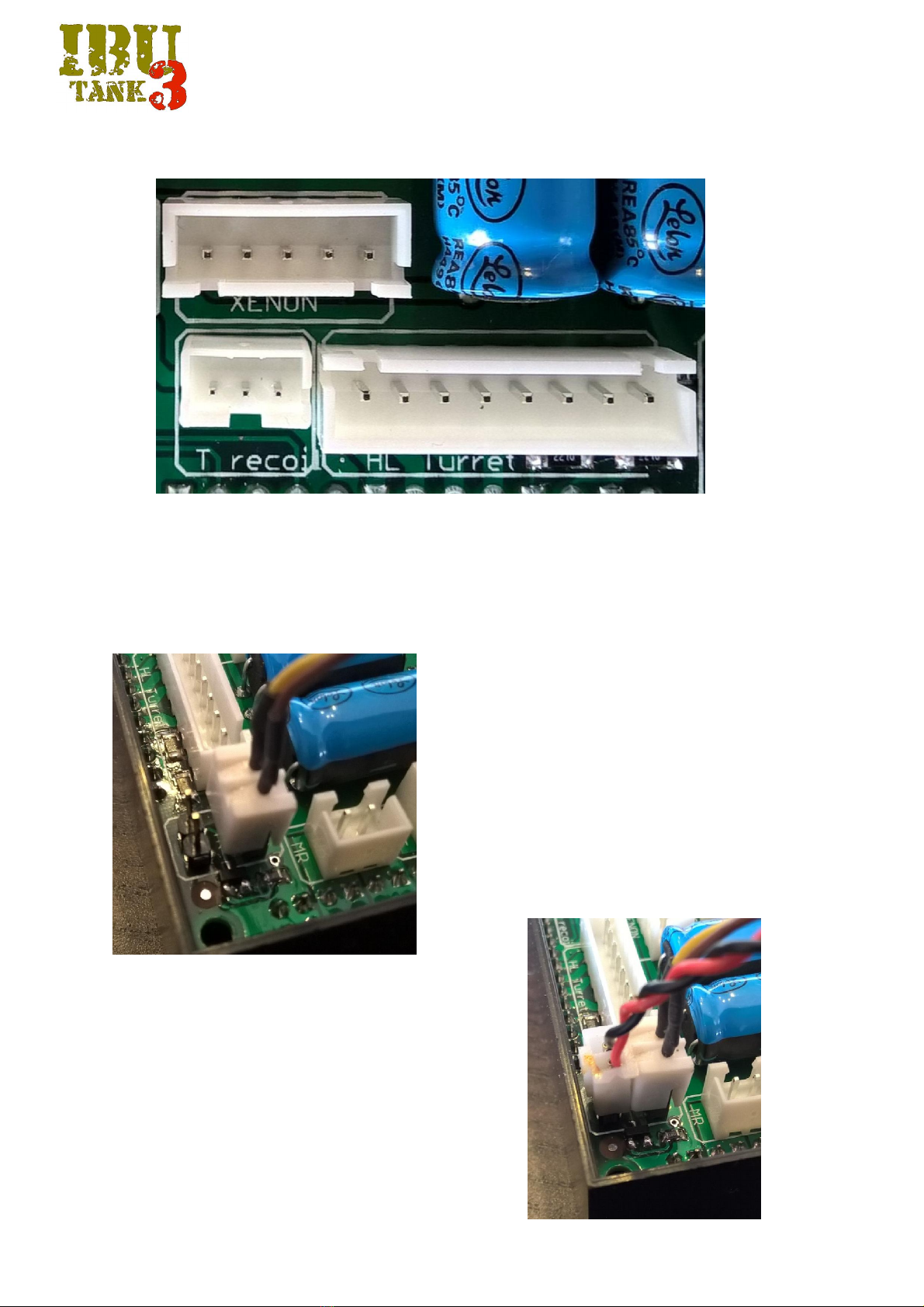
XENON connector
Connect the cable from HL/Taigen Xenon module
T Recoil connector
The IBU3 module allows you to control the Tamiya recoil unit without changes by connecting the cable to this port
Heng Long/Taigen turret port
Taigen recoil connector
The IBU3 module allows to drive the new Taigen recoil units for airsoft
tanks without changes.
Connect the power cable (male) to the female connector as shown in
Figure
Connect the signal cable (female) to the connector
male as shown in Figure

user manual
IBU3 User Manual rev. 1.0 I.B.U. Electronics
http://www.ibu
-
electronics.com
ML connector
Connect the Left motor
BATT connector
Connect power from the battery
MR connector
Connect the Right motor
user manual
IBU3 User Manual rev. 1.0 I.B.U. Electronics
http://www.ibu
-
electronics.com
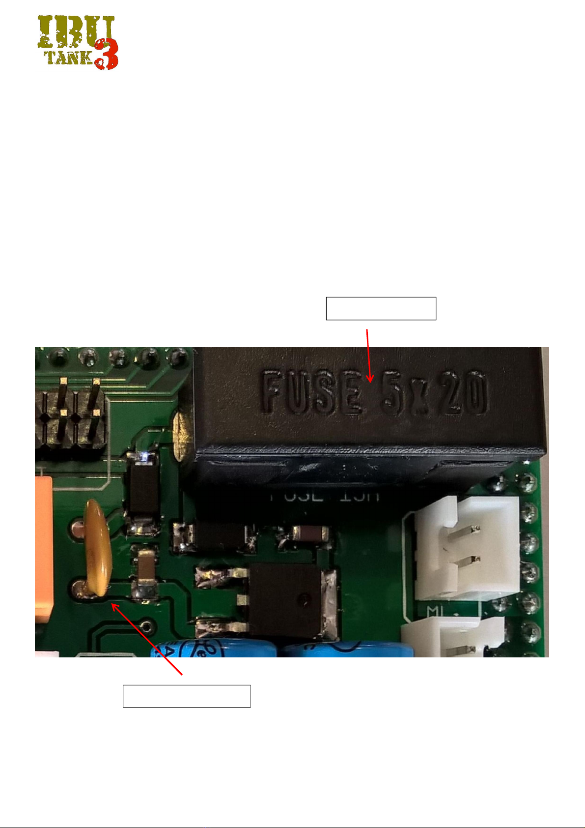
Hardware built in protections
The IBU3 Module is equipped with internal protections.
The 16 Ampere 5x20 Fast Action Fuse (which is the only part serviceable by the user) protects the powertrain
The PTC Resettable fuse (service fuse) protects the all the electronics, in case short circuit or wrong connections this fuse will disconnect
the main supply coming from battery. After a short time this device will reset itself automatically and the electronics will be supplied
again. If the fuse act again disconnect all the cables from the module (except for the battery supply) and check carefully the wirings.
Service Resettable fuse
Geared motors fuse
Table of contents
Popular Control Unit manuals by other brands

Festo
Festo Compact Performance CP-FB6-E Brief description

Elo TouchSystems
Elo TouchSystems DMS-SA19P-EXTME Quick installation guide

JS Automation
JS Automation MPC3034A user manual

JAUDT
JAUDT SW GII 6406 Series Translation of the original operating instructions

Spektrum
Spektrum Air Module System manual

BOC Edwards
BOC Edwards Q Series instruction manual

KHADAS
KHADAS BT Magic quick start

Etherma
Etherma eNEXHO-IL Assembly and operating instructions

PMFoundations
PMFoundations Attenuverter Assembly guide

GEA
GEA VARIVENT Operating instruction

Walther Systemtechnik
Walther Systemtechnik VMS-05 Assembly instructions

Altronix
Altronix LINQ8PD Installation and programming manual


