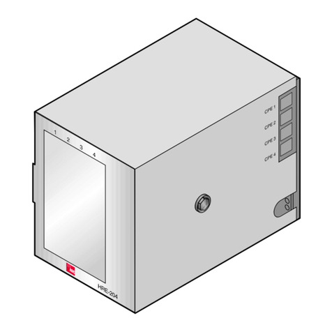
I-DEN IVT-7 NTSC User manual

ADE
CORPORATION
NSTRUCTION
MANUAL

I.
NO.
TB-
Technical
Bulletin
for
model:
IVT-7
DATE:
9/20/90
SUBJECT:
HI-8
Modification
in
units
serial
numbers
10050400
and
higher.
This
unit
has
been
modified
to
accept
HI-8
and
be
adjustable
in
Y/C
delay.
When
using
in
HI-8
format,
make
sure
input
select
Switch
is
in
YC
and
that
the
HI-8
switch
is
in
HI-8
position.
©
Pagel6
3-2
FRONT
OF
PRINTED
CIRCUIT
BOARD
The
front
panel
of
IVI-7
will
be
altered
accordingly
as
below:
,
AUTO
INPUT
SC
SC
IMPEDANCE
FREEZE
SELECT
INVERT
PHASE
MOD
LEVEL
HIGH
75
ON
OFF
VIDEO
YC
ON
OFF
LoGAL
Ye
[BAL
eee
Seopa]
oo
0
@
VIDEO
SETUP
CHROMA
CHROMA
§
OUT
7
LEVEL
LEVEL
PHASE
LEVEL
LEVEL
.
lo
©
Ye
Hig
ab
-
}
OFF
ON
ON
OFF
VIDEO
PHASE
H,
PHASE
Y/C
DELAY
DOC
V.BLK
EN
CORPORATION.
I.
DEN
VIDEOTRONICS
CORPORATION

CHANGES
in
IVT-7
INSTRUCTION
MANUAL
OPagel1
2-3-1
VIDEO
IN
additional
information:
Products
after
serial
No.10050201
have
a
5.5MIlz
frequency
bandwidth
apart
from
the
sub-carrier
filter.
If
there
is
a
large
variation
of
the
color
signal
at
the
output
video
signal
of
the
IV¥-7,
adjust
the
characteristics
of
the
sub-carrier
filter.
OPagel2
2-3-2
YC358
IN
additional
information:
A
Y
signal
input
impedance
selection
switch
is
installed
at
the
front
of
the
PCB
in
products
after
serial
No.
10050101.
Make
sure
this
switch
Is
set
to
75
ohm.
OPagel3
2-3-3
DUB
IN
additional
information:
A
Y
signal
input
impedance
selection
switch
is
installed
at
the
front
of
the
PCB
in
products
after
serial
No.
10050101.
Set
it
so
that
it
matches
the
DUB
Y
output
impedance
of
the
VIR.

OPagei6
3-2
FRONT
OF
PRINTED
CIRCUIT
BOARD
The
front
panel
of
IVI-7
will
be
altered
accordingly
as
below:
AUTO
INPUT
SC
SC
BURST
IMPEDANCE
FREEZE SELECT
INVERT
PHASE
MOD
LEVEL
|
REMOTB
[BAL]
HIGH
75
ON
OFF
VIDEO
YC
ON
OFF
LOCALS
p=
po
Poe
a
Gx]
fe]
fey
fos]
[]
[|
__
0
oO
oO
o
0
VIDEO
SETUP
CHROMA
CHROMA
S
OUT
LEVEL
LEVEL
PHASE
LEVEL
LEVEL
el
le|
aD
Cod
oF
OFF
ON
ON
OFP
VIDEO
PHASE
H.
PHASE
Y/C
DELAY
DOC
—*V.BLK
additional
information:
@IMPEDANCE
SELECT
WIGHN/750hm
(after
S/No.
10050101)
This
switch
is
for
switching
the
Y
input
impedance
between
YC
input
or
DUB
Input.
@BURST
LEVEL
This
adjusts
the
burst
level
of
VIDEO
OUT
and
S
OUT.
O
Pagel8
Current
entry
In
IVT-7'Hanual
reads:
@®CHROMA
LEVEL
VIDEO
OUT
(Standard
position
@
)
llowever
customers
should
note
the
Hanual
now
reads:
@®CHROMA
LEVEL
(standard
position
(@
)
(CHROHA
LEVEL
refers
to
the
chroma
level
of
the
Video
Output
and
YC
Output.
)

Current
entry
in
IVI-7
Manual
reads:
YC
OUT
(standard
position
@
)
However
customers
should
note
the
Manual
now
reads:
@®S
OUT
LEVEL
(standard
position
(@
)
(S
OUT
LEVEL
refers
to
YC358(S-VHS)
output
level)
O
Page20
3-3
REAR
PANEL
The
rear
panel
of
IVI-7
will
be
altered
accordingly
as
below:
Vi
Video
yY/C_In_
Out
Out
Out
In
In
4
Pin
7
Pin
[|
=
©
©
Oe)
('
4
l
_|
Gen-Lock
(4Pin
or
7Pin)
In
O
Page25
(1)
Noise
reduction
additional
information:
Products
after
serial
No.
10050201
have
high
VIDEO
INPUT
bandwidth
characteristics.
-
Because
YC
separation
is
carried
out
in
the
SC
TRAP,
the
chroma
signal
is
insufficiently
removed
from
the
Y
signal.
So,
by
using
a
circuit
to
reduce
noise
in
this
Y
signal,
chroma
components
are
completely
removed
from
the
Y
signal.
Therefore,
VR10
sets
the
voltage
at
JP14
to
+0.12~+0.14V
with
respect
to
the
voltage
at
TP17.

OPage27
SPECIFICATIONS
Current
entry
in
IVI-7
Manual
reads:
freq.response
Composite
-3.0MhzZ
-3dB
However
customers
should
note
the
following
improvement
in
specification:
Freq.response
Composite
-5.5MNHZ
-3dB(Except
SC
TRAP)

DIGITAL
TIME
BASE
CORRECTOR
Nee

IVT-7
INSTRUCTION
MANUAL

Table
of
Contents
SECTION
1
INTRODUCTION
------------------------
2
1-1
GENERAL
DESCRIPTION
-------------------
2
1-2
SPECIFICATIONS
------------------------
2
1-3
FUNCTION
------------------------------
4
1-4
STANDARD
CONFIGURATION
----------------
6
1-5
ACCESSORIES
---------------------------
6
SECTION
2
INSTALLATION
------------------------
9
2-1
UNPACKING
AND
INSPECTION
---~-----------
9
2-2
INSTALLATION
--------------------------
9
2-3
SYSTEM
CONFIGURATION
------------------
10
2-3-1
VIDEO
IN
(VHS,Betamax,...)
-------
11
2-3-2
YC443
IN
(S-VHS,...)
-------------
12
2-3-3
DUB
IN
(U-MATIC,
VHS,...)
--------
13
SECTION
3
OPERATION
---------------------------
14
3-1
FRONT
PANEL
---------------------------
14
3-2
FRONT
OF
PRINTED
CIRCUIT
BOARDS
-------
16
3-3
REAR
PANEL
----------------------------
20
SECTION
4
OPERATING
CONSIDERATIONS
------------
25

SECTION
1
INTRODUCTION
1-1
GENERAL
DESCRIPTION
The
IVT
7
is
a
small
but
multifunctional
digital
time
base
corrector.
Because
it
incorporates
a
frame
memory,
it
can
be
used
to
synchronize
with
reference
Signals
the
recorded
signals
of
a
VTR
which
has
no
input
terminal
for
external
synchronizing
signals.
Therefore,
a
VHS
VTR
or
the
like
can
be
used
fora
system
using
a
video
mixer
or
switcher.
Acceptable
input
signals
are
composite
video
Signals
as
well
as
YC358
and
DUB
signals.
Both
U-MATIC
DUB
and
VHS
DUB
signals
are
acceptable.
For
connection,
see
Section
2-3.
Inputting
YC358
or
DUB
signals
provides
a
high
resolution
of
5.5
MHz
results.
The
functions
of
this
equipment
are
summed
up
under
Section
1-3.
If
there
is
any
point
you
want
to
have
clarified,
please
contact
us.
1-2
SPECIFICATIONS
(1)
Video
input
signals
Composite
video
Y:1.O0Vpp
75
ohm
YC358
Y:1.0Vpp
75
ohm
(4
PIN
or
7PIN)
C:0.286Vpp
75
ohm
(burst
level)
U-DUB
Y:1.O0Vpp
75
ohm

C:
Composite
video
VHS
DUB
Y:1.0Vpp
75
ohm
C:
Composite
video
(2)
GEN-LOCK
input
signal
BB:
0.45Vpp
75
ohm
or
through
out
or
Composite
video:
1.0Vpp
75
ohm
or
through
out
(3)
RF
signal
0.2-2.0Vpp
75
ohm
(4)Video
output
signal
Composite
video-l
1.O0Vpp
75
ohm
Composite
video-2
1.O0Vpp
75
ohm
YC358
Y¥Y:
1.0Vpp
75
ohm
C:
0.286Vpp
75
ohm
(5)
Black
burst
output
signal
0.45Vpp
75
ohm
(6)
Internal
processing
Component
(7)
Sampling
frequency
Y:
13.5
MHz
C:
6.75
MHz
(8)
Quantization
Y:
8
bits
C:
8
bits
(9)
Frequency
characteristics
Y:
5.5
MHz
-3
dB
(10)
DG,DP
2%,
2
(11)
Waveform
characteristic
1%
(
In
case
of
Video-in,
3%)
(12)
S/N
08
dB

1-3
FUNCTION
The
principal
functions
and
features
of
this
equipment
are
as
follows]:
(1)
Freeze
function
In
addition
to
frame
freeze
and
field
freeze
from
the
front
panel,
there
is
an
auto-
freeze
function
which
freezes
and
outputs
the
image
immediately
preceding
the
stoppage
of
input
signals.
This
auto-freeze
function
can
be
turned
on/off
at
the
front
of’
the
printed
circuit
board.
(2)
ACC
function
This
is
to
detect
the
burst
level
of
input
signals
and
automatically
controls
the
chroma
level.
(3)
Chrominance
signal
line
shift
function
Chrominance
signal
line
shifts
which
may
occur
ina
VHS
VTR
or
the
like
can
be
corrected.
This
correction
can
be
made
within
the
range
of
-1H,
OH-,
+1lH,
+2H
by
moving
the
jumper
pin
of
Jl
on
the
digital
circuit
board.
For
how
to
take
out
the
digital
circuit
board,
see
Section
4.
(4)
GEN-LOCK
function
The
output
signal
of
this
equipment
can
be
phase-
synchronized
with
the
GEN-LOCK
input
signal
by
connecting
the
GEN-LOCK
input
connector
on
the
rear

panel
with
a
black
burst
signal
which
makes
a
reference
or
a
stable
composite
video
sienmal
(8.28.,
color
bar
signal).
(5)
DOC
function
When
the
RF
signal
(for
DOC)
of
a
VTR
is
connected
to
the
RF
IN
connector
on
the
rear
panel,
and
when
the
DOC
ON/OFF
switch
on
the
front
panel
is
set
to
ON,
dropout
compensation
can
be
made
line
by
line.
(6)
V,
blanking
can
be
turned
on/off.
VITC
and
other
input
signals
during
the
vertical
blanking
period
can
be
passed
by
turning
off
the
\V.
Blanking
switch
at
the
front
of
the
printed
circuit
board.
(7)
Noise
reduction
function
The
chroma
signal
noise
reduction
function
is
alwavs
at
work,
bringing
about
an
improvement
of
about
-3
dB.
When
the
Y-signal
noise
reduction
function
is
brought
into
play,
vertical
resolution
deteriorates.
Therefore,
a
function
which
detects
vertical
correlation
is
provided
so
as
to
prevent
the
deterioration
of
vertical
resolution.
The
variable
resistor
VRIO
within
the
digital
circuit
board
(underside
performs
the
function
of
adjusting
vertical
correlation
detection
sensitivity.

When
set
at
the
extreme
counterclockwise,
the
Y-
Signal
noise
reduction
function
does
not
work
at
all.
When
turned
clockwise
gradually,
the
function
goes
into
operation.
When
set
at
the
extreme
clockwise,
Y-
Signal
noise
reduction
operates
perfectly,
but
vertical
resolution
deteriorates.
1-4
STANDARD
CONFIGURATION
The
IVT-7
is
composed
of
two
main
circuit
boards
and
a
power
supply.
On
the
front
panel
of
the
chassis
is
a
printed
circuit
board
mounted
with
a
switch
and
an
LED
and
is
connected
with
the
main
circuit
boards
by
cables.
The
rear
panel
forms
one
body
with
the
shield
board
on
which
the
main
boards
are
mounted.
When
the
front
panel
board
and
the
main
board
are
to be
removed,
be
sure
to
cut
off
the
power
supply.
A
simple
configuration
drawing
is
shown
in
Section
4.
1-5
ACCESSORIES
Standard
accessories
Power
cable
1
Spare
fuse
1
Rack
mount
adapter
2

Optionals
TR-7
CA3-2
CA4-2
CA2-2P
CA2-2
Rubber
legs
4
Remote
control
unit.
The
functions
of
TR-7
are
field
freeze,
frame
freeze
and
bypass
control.
Cable
for
YC358
input
(for
7-pin
input)
YC358
input
connectors
provided
are
4-pin
and
7-pin
connectors.
Connect
with
either.
Cable
for
YC358
output.
A
7/4-pin
cable
for
connections
the
YC358
output
signal
of
this
equipment
with
an
S-VHS
or
ED-BETA
VTR
equipped
with
a
4-pin
input
connector.
7/7-pin
cable.
This
cable
is
to
connect
this
equipment
provided
with
a
7-pin
YC358
input
or
output
connector.
U-DUB
input
cable.
This
connector
is
provided
with
a
7-
Pin
connector
at
one
end
and
7-pin
and
BNC
connectors
at
the
other
end.
Connect
one
of
the
7-pin
connectors

With
the
YC
input
connector
of
the
IVT-7.
Connect
the
other
7-pin
connector
with
DUB
OUT
and
the
BNC
connector
with
VIDEO
OUT.
DUB
output
signals
sent
out
by YC
separation
can
be
connected
with
a
3/4"
VTR
(U-MATIC)
or
VHS
VTR.

SECTION
2
INSTALLATION
2-1
UNPACKING
AND
INSPECTION
The
IVT-7
is
shipped
in
adequately
packed
form.
If
the
product
is
found
to
be
damaged
when
unpacked,
contact
the
express
company
or
supplier
without
delay.
The
product
is
packed
in
such
a
manner
that
it
can
be
transported
easily.
When
the
product
is
to
be
moved
or
transported,
use
the
packing
material
used
for
delivery
and
take
care
not
to
apply
abrupt
shocks.
At
the
time
of
unpacking,
make
sure
of
the
accessories
(1-5).
2-2
INSTALLATION
The
IVT-7
not
only
permits
desk-top
use,
but
it
also
can
be
mounted
on
the
19-inch
standard
rack
with
the
aid
of
the
standard
accessory
adapter.
If
the
IVT-7
is
to be
used
in
the
best
condition,
it
should
be
kept
permeable
inside.
For
internal
ventilation,
the
air
for
cooling
is
sucked
in
from
both
sides
and
blown
out
by
the
rear
fan.
Therefore,
the
inlet
and
outlet
ports
should
be
kept
apart
from
the
wall
and
the
floor
to
ensure
sufficient
ventilation.
When
used
on
the
desk
top,
it
should
have
the

standard
accessory
rubber
legs
at
four
points.
Do
not
place
on
the
equipment
any
heavy
object
exceeding
20
kg.
If
anything
is
placed
on
the
equipment,
a
board
of
wood
or
the
like
should
be
placed
between
the
equipment
and
the
object.
2-3
SYSTEM
CONFIGURATION
Here
1S
an
example
of
IVT-7
connection.
In
case
of
no
GEN-LOCK
IN
connection,
the
IVT-7
operates
with
the
aid
of
the
internal
synchronizing
Signal
generator.
When
a
GENLOCK
signal
is
connected,
the
output
signal
of
the
IVT-7
is
svnchronized
with
it.
10

w2-3-1
VIDEO
IN
-»
VIDEO
OUT
YC358
OUT
VIDEO
VIDEO
|
VHS
etc.
[fouT
IN
}
IVT-7
REFERENCE
BB
GEN-LOCK
IN
Open
the
front
panel
and
set
the
input
selection
switch
at
VIDEO.
LED
display
"VIDEO"
on
the
front
panel
will
light
up.
Two
kinds
of
output
signals
are
outputted
at
the
same
time,
but
in
the
bypass
mode
or
when
the
power
supply
is
off,
VIDEO-IN
signals
are
outputted
directly
at
VIDEO
OUT-1.
The
frequency
characteristic
of
the
VIDEO-IN
mode
turn
VR13
on
the
analog
circuit
board
clockwise.
Then
a
characteristic
exceeding
3.0
MHz,
-3
dB
will
be
obtained.
11

J
C)
VR13
ANALOG
PROCESSOR
W2-3-2
YC358
IN
S-VHS
etc.
Is
YC.
>
VIDEO
OUT
OUT
iN}
|
>
YC358
OUT
IVT-—7
REFERENCE
BB
GEN-LOCK
IN
CA2-2P
OY
CA3-2
Open
the
front
panel
and
set
the
input
selection
Switch
to
"YC".
LED
"YC"
on
the
front panel
will
light
up.
Two
Kinds
of
output
signals
are
outputted
at
the
same
time,
but
in
the
bypass
mode
or
when
the
power
supply
is
off,
YC
input
signals
are
outputted
directly
12
Table of contents
