I-Gard mGARD-100 User manual

C-419EM Instruction Manual, March 2015
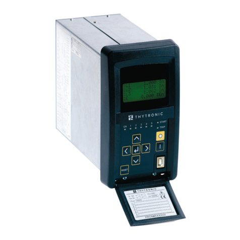
Ground fault relay
microprocessor-based relay
mGARD-100

I-Gard’s commitment to electrical safety provides both industrial and commercial
customers with the products needed to protect their electrical equipment and the
people that operate them.
As the only electrical-safety focused company whose product portfolio includes
neutral grounding resistors, high-resistance grounding systems and optical arc
mitigation, we take pride in our technologies that reduce the frequency and
impact of electrical hazards, such as arc flash and ground faults.
For those customers who have purchased from us over the last 30 years, you
know us for the quality and robustness of our products, our focus on customer
service and technical leadership. We build on this foundation by investing
in developing new products in electrical safety education - including EFC
scholarship program - by actively participating in the IEEE community programs
on technical and electrical safety standard, and working with local universities
at discovering new technologies. We remain unrelenting in our goal of improving
electrical safety in the workplace.
Our commitment to excellence is validated by long-standing relationships with
industry leaders in fields as diverse as petroleum and gas, hospitals, automotive,
data centers, food processing, aerospace, water and waste water plants, and
telecommunications. We provide our customers with the product and application
support required to ensure that their electrical distribution system is safe and reliable.
ABOUT I-GARD

SUBJECT PAGE
1. Features ........................................................................................................................................... 2
2. Introduction ..................................................................................................................................... 2
3. Operation ......................................................................................................................................... 3
3.1 Operation and Glossary of Terms .......................................................................................... 3
Auto Reset: ............................................................................................................................... 3
Chassis Ground: ....................................................................................................................... 3
Interposing Current Sensor: .................................................................................................... 3
Failsafe: ..................................................................................................................................... 3
Non-Failsafe: ............................................................................................................................ 4
Manual Rreset: ......................................................................................................................... 4
3.2 Dipswitch Settings .................................................................................................................. 4
3.3 Indication ................................................................................................................................. 6
mGard-Sym Remote Indicator ................................................................................................ 6
3.4 Reset ........................................................................................................................................ 7
3.5 Ground Fault Test .................................................................................................................... 7
4. Installation Instructions .................................................................................................................. 8
4.1 Mounting .................................................................................................................................. 8
4.2 Built-In Current Transformer ................................................................................................... 9
4.3 Interposing Current Sensor .................................................................................................. 10
4.4 Connections ........................................................................................................................... 12
5. Catalogue Numbers .......................................................................................................................12
6. Service ............................................................................................................................................12
7. Technical Specifications ............................................................................................................... 13
8. Dimensional Drawings .................................................................................................................. 14
TABLE OF CONTENTS

1. FEATURES
• WIDE RANGE OF TRIP LEVEL SETTINGS AND TRIPPING TIME DELAYS
• CAN BE USED WITH INTERNAL OR INTERPOSING EXTERNAL CURRENT SENSOR
• WIDE RANGE AC AND/OR DC CONTROL VOLTAGE
• CONNECTS TO MGARD-SYM REMOTE INDICATOR
-MODBUS CONNECTION TO EXTERNAL NETWORK
-REMOTE DATA COLLECTION
-REMOTE RELAY RESET
-MONITORS UP TO 50 DEVICES ON A SINGLE MODBUS ADDRESS
-ISOLATION PROTECTS YOUR NETWORK
2. INTRODUCTION
The mGARD-100 is a microprocessor-based ground fault relay designed and built to be used on solidly grounded or
resistance grounded systems. This innovative digital electronic relay measures ground fault current using a built-in
2‘’ zero sequence current sensor (ZSCS).
The mGARD-100 reacts to alternating current only and will reject direct current signals. Harmonic ltering can be
enabled using a DIP switch. With the harmonic filtering feature enabled, the mGARD-100 rejects all frequencies
except the fundamental. This can be used to eliminate false tripping when using the relay on systems with
variable frequency drives. With the harmonic filter disabled, the relay will accurately respond to AC currents
between 25 and 400Hz.
By using an interposing current sensor, running the secondary through the mGARD-100 internal ZSCS, the
mGARD-100 can be applied on any system voltage.
The mGARD-100 relay is also available with low voltage DC power supplies including 5V, 12V, 24V and 48V DC.
Other specific ratings are available upon request; please consult I-Gard if other ratings are required.
The output relay has Form “Z” (4 terminal) Normally Open (N.O.) and Normally Closed (N.C.) contacts which may
be used to operate the upstream protective device and to indicate a ground fault in the system. The relay can be
set to operate in any one of the following modes: failsafe; non-failsafe; or auto reset by means of front-accessible
DIP switches.
By double clicking the test/reset button on the unit, a functional test of the mGARD-100 is invoked. A single press of
the remote test/reset button resets the relay after a trip. (It is not necessary to press the test/reset button to invoke
auto reset).

The green LED indicates two functions: When slow ashing it means control power is applied to terminals N- and L+;
when fast blinking it denotes the relay has sensed a ground fault current higher than the trip level threshold selected
for a period longer than the tripping time delay and that the output contacts have operated.
The mGARD-100 operates on any control voltage from 40 to 240V AC or DC, and contains an isolated power supply.
The seven position terminal block is pull-apart type that eases the wiring in the field.
A three position, pull-apart terminal connects the relay to the mGARD-SYM remote indicator (with modbus
connectivity) for remote test / reset and monitoring.
Special consideration must be taken in the selection of the neutral grounding resistor in a high resistance grounded
system as the capacitance-to-ground charging current on a system will vary depending on: the overall length of the
cables; the types of loads; the quality of insulation on the phase conductors; the surrounding equipment grounding,
cable trays, junction boxes, the type of sensor, etc. A “Rule-of-Thumb” for systems 600V and lower: The charging
current is 0.5 Amps per 1000 kVA of sensor capacity. In electrical systems of 600V and below it is common to use a
5 Ampere continuous rating for the neutral grounding resistor and setting the pickup current at 20% of that value (1
Ampere) for all relays and coordinating between upstream and downstream relays by selecting different time delays.
3. OPERATION
3.1 OPERATION AND GLOSSARY OF TERMS
Auto Reset:
After a trip, the relay will automatically reset itself three seconds after the ground fault current drops below the trip
current set point. The auto reset feature can be used in both failsafe and non-failsafe modes.
Chassis Ground:
Chassis ground is the ground to which all of the non-current carrying metal equipment is connected/bonded.
Typically, equipment grounding is provided by means of a ground bus. A solid connection is to be made from
terminal 7 of the mGARD-100 to the nearest chassis ground to ensure the relay complies with the specified
electromagnetic compatibility (EMC) standards. If using an external zero sequence current sensor, do not ground
any of the ZSCS secondary wires.
Interposing Current Sensor:
Interposing Zero Sequence Current Sensors (ZSCS) are required for any of the following applications:
• The ground fault trip current setting levels are higher than the 30 mA –12 Amp range available with the built-in
2” ZSCS.
• The size of the power conductors on which the mGARD-100 is being applied is too large for the 2” built-
in ZSCS.
• The system primary phase current on which the mGARD-100 is being applied exceeds 250 Amps continuous.
Failsafe:
The output relay changes state when control power is applied to terminals N- & L+. The N.O. contact closes and
the N.C. contact opens. When a trip occurs or control voltage is removed, the N.O. contact is opened and the N.C.
contact is closed.

Non-Failsafe:
The output relay does not change state when control power is applied to terminals N- & L+. When a trip occurs the
N.O. contact is closed and the N.C. contact is opened.
Ground (Earth):
The conductive mass of the earth, at which point all the exposed conductive parts of the system should be bonded
at a conventional voltage value of zero.
Ground Fault:
A ground fault is understood to be an accidental contact between a live conductor at phase potential and ground.
Manual Reset:
A N.O. contact RESET pushbutton located on the relay must be pressed once to reset the output relay after a trip,
providing the ground fault has been cleared.
Pickup Current / Trip Levels:
The value of the zero sequence (fault) current at which the relay is set to trip (the relay contacts change their state).
Time Delay:
Intentional period of time programmed to elapse before the tripping (operation) of the relay. It should not be confused
with the breaking (opening) time of the protection device.
Zero Sequence Current:
A vector summation of all electrical currents in an electrical line. Theoretically in any electrical system the summation
of all the electrical currents is zero. When the resulting summation value is other than zero it is an indication of a
current leakage to ground.
3.2 DIPSWITCH SETTINGS
The DIP switches are mounted inside of the relay and are accessible through the front cover. It is recommended that
all of the DIP switches be set at one time and before energizing the relay.
Changes to the DIP switch settings when the mGARD-100 relay is energized may be performed without having any
adverse effect on the relay. Table 3.0 displays all DIP switch selectable options.

Table 3.0 mGARD-100 DIP switch settings
(In the table above ‘R’ denotes right and ‘L’ denotes left
1Harmonic Filter L
R
Disabled
Enabled
2Trip Contacts L
R
Non-Failsafe
Failsafe
3Auto Reset L
R
Disabled
Enabled
4, 5, 6, 7
Ground Fault
Trip
Current Limit
Internal ZSCS 100:1 Interposing 1000:1 Interposing
L L L L
L L L R
L L R L
L L R R
L R L L
L R L R
L R R L
L R R R
R L L L
R L L R
R L R L
R L R R
R R L L
R R L R
R R R L
R R R R
30
40
60
90
150
250
400
600
900
1500
2500
4
6
9
10
12
3
4
6
9
15
25
40
60
90
150
250
400
600
900
1000
1200
30
40
60
90
150
250
400
600
900
150
250
4000
6000
9000
10000
12000
8, 9, 10 Trip Time Delay
L L L
L L R
L R L
L R R
R L L
R L R
R R L
R R R
20 milliseconds
50 milliseconds
100 milliseconds
200 milliseconds
500 milliseconds
1 second
2 seconds
5 seconds
SWITCH MEANINGFUNCTION SET TO
-Factory Setting
Trip levels can be scaled down by adding turns through the current sensor. Tables 3.1 display the trip levels with
multiple turns through the ZSCS.

Table 3.1 mGARD-100 Trip Levels vs. Turns through ZSCS.
30mA (L, L, L, L) 30mA 15mA 10mA 2.5mA 2mA
40mA (L, L, L, R) 40mA 20mA 14.3mA 5mA 4mA
60mA (L, L, R, L) 60mA 30mA 20mA 7.5mA 6mA
90mA (L, L, R, R) 90mA 45mA 30mA 12.5mA 10mA
150mA (L, R, L, L) 150mA 75mA 50mA 25mA 20mA
250mA (L, R, L, R) 250mA 125mA 83.3mA 30mA 24mA
400mA (L, R, R, L) 400mA 200mA 133.3mA 37.5mA 30mA
600mA (L, R, R, R) 600mA 300mA 200mA 52.5mA 42mA
900mA (R, L, L, L) 900mA 450mA 300mA 75mA 60mA
1500mA (R, L, L, R) 1500mA 750mA 500mA 125mA 100mA
2500mA (R, L, R, L) 2500mA 1250mA 833.3mA 150mA 120mA
4A (R, L, R, R) 4A 2A 1.33A 250mA 200mA
6A (R, R, L, L) 6A 3A 2A 600mA 480mA
9A (R, R, L, R) 9A 4.5A 3A 750mA 600mA
10A (R, R, R, L) 10A 5A 3.33A 1.05A 840mA
12A (R, R, R, R) 12A 6A 4A 1.5A 1.2A
DIP SETTING 1 TURN 2 TURNS 3 TURNS 4 TURNS
-Applies to both internal and external CT
5 TURNS
3.3 INDICATION
There is one green LED on the front of the mGARD-100:
LED Off: No control voltage or mGARD-100 defective
LED Slow Flashing: Normal, control voltage on
LED Fast Blinking: Ground Fault Trip
LED Steady On: Control voltage too low or mGARD-100 defective
MGARD-SYM REMOTE INDICATOR
The mGARD-SYM is a remote display indicator that is used in conjunction with I-Gard relays. The indicator has the
capability to interconnect and work with up to 50 relays including the mGARD-100 relay in a bus network topology
and provides detailed device status information.
As shown in Figure 3.0, the display has a 4-line screen that shows a list of connected devices. A device can be
selected and viewed in detail. The relay mode, delay and trip level settings can be viewed (but not altered). The reset
and test functions can also be performed directly from the display.
Fault levels are displayed as a percentage of the selected pickup (trip) current level. If the trip level is 1 Amp
and there is a 500 mA fault current, the reading on the display will appear as 50%. Screen navigation is done
using a 4-button interface. The menus are displayed on the right side of the LCD; the left side is reserved for
viewing relay information.
To properly display current levels on the mGARD-SYM, the trip levels can be set to match to a 100:1 or 1000:1
interposing ZSCS using the mGARD-SYM interface.

The mGARD-SYM also provides an isolated connection to an external modbus RTU network. All 50 devices can be
monitored remotely using a single configurable modbus address. Built-in electrical isolation protects the modbus
network from hazardous voltages or transients. The display is compatible with several modbus speeds; 1200, 2400,
4800, 9600, 19200 and 38400 baud. Stop bits are selectable (1 or 2). Data available through modbus includes relay
status and fault levels as well as remote reset.
For more information on the mGARD-SYM display refer to the mGARD-SYM manual (C-416EM).
Figure 3.0 mGARD-SYM Remote Indicator
3.4 RESET
The mGARD-100 has a built in test/reset pushbutton button located on the faceplate. After a trip, the relay remains
in the tripped state until the ground fault has been cleared and the reset button has been pressed, or the control
voltage is removed from terminals L- & N+.
It is NOT necessary to press the remote test/reset button after the ground fault has been cleared when the
mGARD-100 is set in the pulsed trip auto reset mode. In this mode the relay will reset automatically in 3 seconds.
For remote reset capability, the relay must be connected to an mGARD-SYM remote indicator.
3.5 GROUND FAULT TEST
Double clicking the pushbutton located on the relay faceplate invokes a relay test. A simulated current which
exceeds the trip current set on the trip level DIP switches replaces the measured current. Once the trip delay time
set on the trip delay DIP switch has elapsed, the relay should trip and the green LED will blink at a fast rate. This
procedure tests the functionality of the unit.
After the trip, if the relay operating mode is manual reset, the output relay will remain tripped and the green LED
will blink fast until the reset button is pressed. If the relay operating mode is pulsed trip auto reset, the output relay
will reset and the green LED will revert to a slow ash 3 seconds after the test button was pushed or the test was
remotely invoked.

4. INSTALLATION INSTRUCTIONS
Hazard of Electrical Shock, Burn or Explosion
All installation, servicing and testing referred to in this manual must be
performed by qualified personnel. All power should be disconnected
prior to removing covers or enclosures and where live conductors
may otherwise be exposed.
Failure to observe these precautions may result in death or severe
personal injury and damage to equipment. Before placing an
intentional ground fault on the power system, check that a fault does
not already exist. Any test ground fault equipment must be rated for
full system voltage and be fused for protection.
DANGER
The internal electronics have been encapsulated in epoxy to improve the performance in high vibration
environments. Try to keep the exposure to mechanical shock and vibration to a minimum and place the mGARD-100
in a clean dry enclosure. Locate the relay close to the isolating device (circuit breaker or contactor) that is protecting
the circuit being monitored.
When using an interposing current sensor, keep the distance between the relay and the sensor as short as possible.
Use twisted cable and increase the gauge of the conductor as per the table below:
Table 4.0 ZSCS secondary wire run-length
Up to 300 Ft. / 91m. 16
301ft / 92m to 450ft / 137m 14
MAXIMUM CABLE RUN IN FEET/METERS MINIMUM WIRE GAUGE
Provide maximum clearance between the mGARD-100 (and the interposing ZSCS if required) and any strong
magnetic flux producing devices such as power transformers, autotransformers, control transformers, reactors, and
high power conductors and bus work.
4.1 MOUNTING
Refer to Figure 8.0 for mounting dimensions of the mGARD-100 relay. The mGARD-100 is designed to be mounted
with either mounting screws or on a 35 mm DIN rail.
Two #8-32 x 3/4” (M4 x 20) mounting screws are required for screw mounting.
For DIN rail mounting the rail should be bolted to a flat surface. Install the DIN rail horizontally. Allow at least ¾” (20
mm) of rail to extend beyond each end of the relay. Secure the relay to the DIN rail ensuring the release latch at the
bottom of the relay engages the rail. If the relay is to be mounted in any other position take appropriate steps to
prevent the relay from disengaging from the DIN rail.

4.2 BUILT-IN CURRENT TRANSFORMER
The mGARD-100 has a built-in current sensor (ZSCS) with 2.0” (50.8 mm) opening. The maximum continuous
primary phase current is 250 Amps. Refer to Table 4.1 below to determine the cable sizes that will fit through the
internal ZSCS.
WIRE SIZE 14 12 10 8 6 4 2
Diameter (inches) 0.126 0.142 0.179 0.241 0.31 0.358 0.418
of Cable (mm) 3.2 3.6 4.6 6.1 7.9 9.1 10.6
Table 4.1 Number of Conductors through the window of the mGard-100
3 Cables in.
(form factor 2.16) mm
0.27 0.3 0.39 0.52 0.67 0.77 0.95
6.9 7.8 10 13 17 20 23
4 Cables in.
(form factor 2.42) mm
0.3 0.34 0.43 0.59 0.75 0.87 1.02
7.74 8.7 11 15 19 22 26
6/7 Cables in.
(form factor 3.0) mm
0.37 0.43 0.54 0.73 0.93 1.07 1.26
9.6 10.8 14 18 24 27 32
9/10 Cablse in.
(form factor 3.85) mm
0.49 0.55 0.69 0.93 1.19 1.38 1.62
12.3 13.9 18 24 30 35 41
12 Cables in.
(form factor 4.15) mm
0.52 0.59 0.75 1 1.29 1.47 1.74
13.3 14.9 19 25 33 38 44
Sensor Type Inside
Diameter in mm
mGARD-100 T3A T6A
2.0 2.75 5.75
50 70 146
NO. OF CABLES IN FEEDER
Figure 4.0 illustrates a wiring arrangement for detecting ground faults on a solidly grounded system. Pass the
neutral and phase conductors through the ZSCS window. Note that the relay is located downstream of the neutral
ground point.
Figure 3.0 mGARD-SYM Remote Indicator

4.3 INTERPOSING CURRENT SENSORS
Refer to the glossary of terms to determine if an interposing current sensor is required for the application.
The mGARD-100 will work with I-Gard TxA and Rx-yA type zero sequence current sensors. Contact I-Gard for
the catalogue number of the zero sequence current sensor with the correct opening diameter required for the
application in case it is not shown on the table below or refer to the manual C-700 available at www.i-gard.com.
Refer to Figure 4.1, pass the phase and neutral conductors through the window of the interposing zero sequence
current sensor. Note that the relay is located downstream from the neutral ground point.
Position the cable in the centre of the zero sequence current sensor window opening. Keep cables and bus-work
clear of the split on split core zero sequence current sensors (T3A-S and T6A-S).
The two secondary terminals of the external zscs are to be routed through the window of the mGARD-100. If using
an mGARD-SYM, use the display to select the interposing I-Gard sensor that you are using to properly display
current levels.
Figure 4.1: mGARD-100 wired for external current sensor, failsafe operating mode, auto-reset with mGARD-SYM

Figure 4.2: mGARD-100 relay monitoring a resistance grounded system and operating in failsafe mode.
Figure 4.2 shows an mGARD-100 relay operating in non-failsafe mode. The relay is monitoring the neutral conductor
in a resistance grounded system.
Figure 4.3 shows a system with several mGARD-100 relays monitoring branch circuits.
Figure 4.3: mGARD-100 relays used to monitor branch circuits, with mGARD-SYM remote indicator.

4.4 CONNECTIONS
All connections to the mGARD-100 are by means of screw clamp terminals rated 10 Amps, 300V. Terminals will
accept any wire gauges from #26 to #12 AWG solid or stranded conductors. The terminals are pull-apart style to
simplify wiring.
Connect AC or DC control power to terminals N- and L+.
In order to meet the Electromagnetic Compatibility (EMC) requirements a chassis bond is required between
terminal 7 and the nearest ground point. This distance should be kept to a minimum. If the mGARD-100 is
mounted on 35mm DIN rail, a DIN rail mounted ground terminal block can be installed beside the relay to act as
the chassis ground point.
mGARD-100 30mA-12A 20ms to 10s 2” window
CATALOGUE NUMBER LEVEL DELAY NOTES
mGARD-100 relay can be ordered with several low voltage DC power supplies as listed below in Table 5.1.
Table 5.1 mGARD-100 DC control voltage options
12V (9-18 VDC) /12DCV mGARD-100 /12DCV
24V (18-36 VDC) /24DCV mGARD-100 /24DCV
DC VOLTAGE RANGE CATALOGUE NUMBER SUFFIX EXAMPLE
6. SERVICE
For assistance in installation, set-up or testing please contact your nearest I-Gard representative, a list of
representatives is available at www.i-gard.com.
There are no recommended, user-serviceable parts in the mGARD-100. All other service should be referred
to qualified factory representatives, other than direct replacement of entire modules to I-Gard. Please visit the
I-Gard website for information regarding field service representatives in your area.
Note: Please ensure that proper authorization is obtained from I-Gard before returning any material.
5. CATALOGUE NUMBERS
All mGARD-10 relays can be ordered with several low voltage DC power supplies as listed below in Table 5.1.
control voltage, for use on 660V maximum, 50/60Hz power system.
Table 5.0 mGARD-100 relay catalogue number

7. TECHNICAL SPECIFICATIONS
Control Power:
3VA AC or 3W DC
40-240V AC/DC ±10% (36-264V AC/DC)
DC Control Power:
5V DC: 4.5-9 VDC, 1.5W
12V DC: 9-18 VDC, 1.5W
24V DC: 18-36 VDC, 1.5W
48V DC: 36-76 VDC, 1.5W
Temperature Range (Celsius):
Operating Temperature: -40OC to +65OC
Storage Temperature: -40OC to +85OC
Dielectric:
Relay contacts to chassis:
1480V rms. for 1 minute
Control terminals to chassi:
1480V rms. for 1 minute
Ground Fault:
Pickup Settings:
30mA, 40mA, 60mA, 90mA,
150mA, 250mA, 400mA, 600mA,
900mA, 1.5A, 2.5A, 4A, 6A, 9A,
10A, 12A
Pickup Tolerance: –15%, +0%
Delay Settings:
20ms, 50ms, 100ms, 200ms, 0.5s,
1s, 2s, 5s
Delay Tolerance: ±2.5%
Thermal Withstand:
Internal ZSCS:
10000 Amps for 1 seconds
Output Contacts:
Main Trip Relay:
Type: Form Z (N.O. and N.C. pair)
Rating: 10A @ 250V AC, resistive
10A @ 30V DC, resistive
Terminal Contact Material:
Clamping screw: nickel-plated brass
Plug contacts: tin-plated bronze
Physical:
Weight: 0.40 kg ( 0.88 lbs)
Dimension: See Figs. 8.0
Mounting:
Din Rail: 35mm
Two Screw: #8 x 3/4” (M4 x 20 mm)
Standards: CSA
Notes:
The mGARD-100 contains:
• An isolated power supply.
• A single Dual Pole Dual Throw (DPDT, 2 Form
C) relay for true failsafe operation.
30mA 25-30ms 20-25
40mA 25-30ms 20-25
60mA 25-30ms 20-25
90mA 25-30ms 20-25
150mA 25-30ms 20-25
250mA 25-30ms 20-25
400mA 25-30ms 20-25
600mA 30-35ms 25-30
900mA 25-30ms 20-25
1.5A 25-30ms 20-25
2.5A 25-30ms 20-25
4A 25-30ms 20-25
6A 30-35ms 20-25
9A 30-35ms 25-30
10A 25-35ms 25-30
12A 25-35ms 30-25
CURRENT
SETTING
DELAY (MS) WHEN CURRENT
EXCEEDS TRIP LEVEL BY FACTOR
Table 7.0 mGARD-100 timing with delay set to 20ms
X2 X4

I-GARD RESERVES THE RIGHT TO CHANGE SPECIFICATIONS OF ITS PRODUCTS WITHOUT NOTICE.
8. DIMENSIONAL DRAWINGS
Figure 8.0 mGARD-100 dimensions in millimetres (inches)

NOTES
Table of contents
Other I-Gard Relay manuals


