manuals.online logo
Brands
  1. Home
  2. •
  3. Brands
  4. •
  5. LOVATO ELECTRIC
  6. •
  7. Relay
  8. •
  9. LOVATO ELECTRIC EXS4000 User manual

LOVATO ELECTRIC EXS4000 User manual

1
I645 GB F 02 22 31100483
WARNING!
–
Carefully read the manual before the installation or use.
–
This equipment is to be installed by qualified personnel, complying to current standards, to
avoid damages or safety hazards.
–
Before any maintenance operation on the device, remove all the voltages from measuring and supply inputs and
short- circuit the CT input terminals.
–
The manufacturer cannot be held responsible for electrical safety in case of improper use of the equipment.
–
Products illustrated herein are subject to alteration and changes without prior notice. Technical data and
descriptions in the documentation are accurate, to the best of our knowledge, but no liabilities for errors, omissions
or contingencies arising there from are accepted.
–
A circuit breaker must be included in the electrical installation of the building. It must be installed close by the
equipment and within easy reach of the operator. It must be marked as the disconnecting device of the
equipment: IEC /EN 61010-1 § 6.11.3.1
–
Clean the device with a soft dry cloth; do not use abrasives, liquid detergents or solvents.
ATTENZIONE!
–
Leggere attentamente il manuale prima dell’utilizzo e l’installazione.
–
Questi apparecchi devono essere installati da personale qualificato, nel rispetto delle vigenti
normative impiantistiche, allo scopo di evitare danni a persone o cose.
–
Prima di qualsiasi intervento sullo strumento, togliere tensione dagli ingressi di misura e di alimentazione
e cortocircuitare i trasformatori di corrente.
–
Il costruttore non si assume responsabilità in merito alla sicurezza elettrica in caso di utilizzo improprio del dispositivo.
–
I prodotti descritti in questo documento sono suscettibili in qualsiasi momento di evoluzioni o di modifiche. Le
descrizioni ed i dati a catalogo non possono pertanto avere alcun valore contrattuale.
–
Un interruttore o disgiuntore va compreso nell’impianto elettrico dell’edificio. Esso deve trovarsi in stretta vicinanza
dell’apparecchio ed essere facilmente raggiungibile da parte dell’operatore. Deve essere marchiato come il
dispositivo di interruzione dell’apparecchio: IEC/ EN 61010-1 § 6.11.3.1.
–
Pulire l’apparecchio con panno morbido, non usare prodotti abrasivi, detergenti liquidi o solventi.
ATTENTION!
–
Lire attentivement le manuel avant toute utilisation et installation.
–
Ces appareils doivent être installés par un personnel qualifié, conformément aux normes en vigueur
en matière d'installations, afin d'éviter de causer des dommages à des personnes ou à des biens.
–
Avant toute intervention sur l'instrument, mettre les entrées de mesure et d'alimentation hors tension et court-
circuiter les transformateurs de courant.
–
Le constructeur n'assume aucune responsabilité quant à la sécurité électrique en cas d'utilisation impropre
du dispositif.
–
Les produits décrits dans ce document sont susceptibles d'évoluer ou de subir des modifications à n'importe
quel moment. Les descriptions et caractéristiques techniques du catalogue ne peuvent donc avoir aucune
valeur contractuelle.
–
Un interrupteur ou disjoncteur doit être inclus dans l'installation électrique du bâtiment. Celui-ci doit se trouver
tout près de l'appareil et l'opérateur doit pouvoir y accéder facilement. Il doit être marqué comme le dispositif
d'interruption de l'appareil : IEC/ EN 61010-1 § 6.11.3.1.
–
Nettoyer l’appareil avec un chiffon doux, ne pas utiliser de produits abrasifs, détergents liquides ou solvants.
ACHTUNG!
–
Dieses Handbuch vor Gebrauch und Installation aufmerksam lesen.
–
Zur Vermeidung von Personen- und Sachschäden dürfen diese Geräte nur von qualifiziertem
Fachpersonal und unter Befolgung der einschlägigen Vorschriften installiert werden.
UWAGA!
–
Przed uĪyciem i instalacjąurządzenia naleĪy uwaĪnie przeczytaüniniejsząinstrukcjĊ.
–
W celu unikniĊcia obraĪeĔosób lub uszkodzenia mienia tego typu urządzenia musząbyü
instalowane przez wykwalifikowany personel, zgodnie z obowiązującymi przepisami.
–
Przed rozpoczĊciem jakichkolwiek prac na urządzeniu naleĪy odáączyünapiĊcie od wejĞü pomiarowych i
zasilania oraz zewrzeüzaciski przekáadnika prądowego.
–
Producent nie przyjmuje na siebie odpowiedzialnoĞci za bezpieczeĔstwo elektryczne w przypadku
niewáaĞciwego uĪytkowania urządzenia.
–
Produkty opisane w niniejszym dokumencie mogąbyüw kaĪdej chwili udoskonalone lub zmodyfikowane.
Opisy oraz dane katalogowe nie mogąmieüw związku z tym Īadnej wartoĞci umownej.
–
W instalacji elektrycznej budynku naleĪy uwzglĊdniüprzeáącznik lub wyáącznik automatyczny. Powinien on
znajdowaüsiĊw bliskim sąsiedztwie urządzenia i byüáatwo osiągalny przez operatora. Musi byüoznaczony jako
urządzenie sáuĪące do wyáączania urządzenia: IEC/ EN 61010-1 § 6.11.3.1.
–
Urządzenie naleĪy czyĞciümiĊkkąszmatką, nie stosowaüĞrodkow Ğciernych, páynnych detergentow lub rozpuszczalnikow.
–
Vor jedem Eingriff am Instrument die Spannungszufuhr zu den Messeingängen trennen und die Stromwandler
kurzschlieȕen.
–
Bei zweckwidrigem Gebrauch der Vorrichtung übernimmt der Hersteller keine Haftung für die elektrische Sicherheit.
–
Die in dieser Broschüre beschriebenen Produkte können jederzeit weiterentwickelt und geändert werden. Die im
Katalog enthaltenen Beschreibungen und Daten sind daher unverbindlich und ohne Gewähr.
–
In die elektrische Anlage des Gebäudes ist ein Ausschalter oder Trennschalter einzubauen. Dieser muss sich in
unmittelbarer Nähe des Geräts befinden und vom Bediener leicht zugänglich sein. Er muss als Trennvorrichtung für
das Gerät gekennzeichnet sein: IEC/ EN 61010-1 § 6.11.3.1.
–
Das Gerät mit einem weichen Tuch reinigen, keine Scheuermittel, Flüssigreiniger oder Lösungsmittel verwenden.
ADVERTENCIA
–
Leer atentamente el manual antes de instalar y utilizar el regulador.
–
Este dispositivo debe ser instalado por personal cualificado conforme a la normativa de
instalación vigente a fin de evitar daños personales o materiales.
–
Antes de realizar cualquier operación en el dispositivo, desconectar la corriente de las entradas de
alimentación y medida, y cortocircuitar los transformadores de corriente.
–
El fabricante no se responsabilizará de la seguridad eléctrica en caso de que el dispositivo no se utilice de
forma adecuada.
–
Los productos descritos en este documento se pueden actualizar o modificar en cualquier momento. Por
consiguiente, las descripciones y los datos técnicos aquí contenidos no tienen valor contractual.
–
La instalación eléctrica del edificio debe disponer de un interruptor o disyuntor. Éste debe encontrarse cerca del
dispositivo, en un lugar al que el usuario pueda acceder con facilidad. Además, debe llevar el mismo marcado que
el interruptor del dispositivo (IEC/ EN 61010-1 § 6.11.3.1).
–
Limpiar el dispositivo con un trapo suave; no utilizar productos abrasivos, detergentes líquidos ni disolventes.
UPOZORNČNÍ
–
Návod se pozornČproþtČte, než zaþnete regulátor instalovat a používat.
–
Tato zaĜízení smí instalovat kvalifikovaní pracovníci v souladu s platnými pĜedpisy a normami
pro pĜedcházení úrazĤosob þi poškození vČcí.
–
PĜed jakýmkoli zásahem do pĜístroje odpojte mČĜicí a napájecí vstupy od napČtí a zkratujte transformátory proudu.
–
Výrobce nenese odpovČdnost za elektrickou bezpeþnost v pĜípadČnevhodného používání regulátoru.
–
Výrobky popsané v tomto dokumentu mohou kdykoli projít úpravami þi dalším vývojem. Popisy a údaje uvedené v
katalogu nemají proto žádnou smluvní hodnotu.
–
Spínaþþi odpojovaþje nutno zabudovat do elektrického rozvodu v budovČ. Musejí být nainstalované v tČsné
blízkosti pĜístroje a snadno dostupné pracovníku obsluhy. Je nutno ho oznaþit jako vypínací zaĜízení pĜístroje:
IEC/ EN 61010-1 § 6.11.3.1.
–
PĜístroj þistČte mČkkou utČrkou, nepoužívejte abrazivní produkty, tekutá þistidla þi rozpouštČdla.
AVERTIZARE!
–
CitiĠi cu atenĠie manualul înainte de instalare sau utilizare.
–
Acest echipament va fi instalat de personal calificat, în conformitate cu standardele actuale,
pentru a evita deteriorări sau pericolele.
–
Înainte de efectuarea oricărei operaĠiuni de întreĠinere asupra dispozitivului, îndepărtaĠi toate tensiunile de la intrările
de măsurare úi de alimentare úi scurtcircuitaĠi bornele de intrare CT.
–
Producătorul nu poate fi considerat responsabil pentru siguranĠa electricăîn caz de utilizare incorectăa
echipamentului.
–
Produsele ilustrate în prezentul sunt supuse modificărilor úi schimbărilor fărănotificare anterioară. Datele tehnice
úi descrierile din documentaĠie sunt precise, în măsura cunoútinĠelor noastre, dar nu se acceptănicio răspundere
pentru erorile, omiterile sau evenimentele neprevăzute care apar ca urmare a acestora.
–
Trebuie inclus un disjunctor în instalaĠia electricăa clădirii. Acesta trebuie instalat aproape de echipament úi
într-o zonăuúor accesibilăoperatorului. Acesta trebuie marcat ca fiind dispozitivul de deconectare al
echipamentului: IEC/EN 61010-1 § 6.11.3.1.
–
CurăĠaĠi instrumentul cu un material textil moale úi uscat; nu utilizaĠi substanĠe abrazive, detergenĠi lichizi sau
solvenĠi.
ɊɋɀȿɎɊɋɀɁȿɀɈɃɀ!
–
ɉɪɟɠɞɟ ɱɟɦ ɩɪɢɫɬɭɩɚɬɶ ɤɦɨɧɬɚɠɭ ɢɥɢ ɷɤɫɩɥɭɚɬɚɰɢɢ ɭɫɬɪɨɣɫɬɜɚ, ɜɧɢɦɚɬɟɥɶɧɨ ɨɡɧɚɤɨɦɶɬɟɫɶ ɫ
ɨɞɟɪɠɚɧɢɟɦ ɧɚɫɬɨɹɳɟɝɨ ɪɭɤɨɜɨɞɫɬɜɚ.
–
ȼɨ ɢɡɛɟɠɚɧɢɟ ɬɪɚɜɦ ɢɥɢ ɦɚɬɟɪɢɚɥɶɧɨɝɨ ɭɳɟɪɛɚ ɦɨɧɬɚɠ ɞɨɥɠɟɧ ɫɭɳɟɫɬɜɥɹɬɶɫɹ ɬɨɥɶɤɨ ɤɜɚɥɢɮɢɰɢɪɨɜɚɧɧɵɦ
ɩɟɪɫɨɧɚɥɨɦ ɜɫɨɨɬɜɟɬɫɬɜɢɢ ɫɞɟɣɫɬɜɭɸɳɢɦɢ ɧɨɪɦɚɬɢɜɚɦɢ.
–
ɉɟɪɟɞ ɩɪɨɜɟɞɟɧɢɟɦ ɥɸɛɵɯ ɪɚɛɨɬ ɩɨ ɬɟɯɧɢɱɟɫɤɨɦɭ ɨɛɫɥɭɠɢɜɚɧɢɸ ɭɫɬɪɨɣɫɬɜɚ ɧɟɨɛɯɨɞɢɦɨ ɨɛɟɫɬɨɱɢɬɶ ɜɫɟ
ɢɡɦɟɪɢɬɟɥɶɧɵɟ ɢɩɢɬɚɸɳɢɟ ɜɯɨɞɧɵɟ ɤɨɧɬɚɤɬɵ, ɚɬɚɤɠɟ ɡɚɦɤɧɭɬɶ ɧɚɤɨɪɨɬɤɨ ɜɯɨɞɧɵɟ ɤɨɧɬɚɤɬɵ
ɬɪɚɧɫɮɨɪɦɚɬɨɪɚ ɬɨɤɚ (ɌɌ).
–
ɉɪɨɢɡɜɨɞɢɬɟɥɶ ɧɟ ɧɟɫɟɬ ɨɬɜɟɬɫɬɜɟɧɧɨɫɬɶ ɡɚ ɨɛɟɫɩɟɱɟɧɢɟ ɷɥɟɤɬɪɨɛɟɡɨɩɚɫɧɨɫɬɢ ɜɫɥɭɱɚɟ ɧɟɧɚɞɥɟɠɚɳɟɝɨ
ɢɫɩɨɥɶɡɨɜɚɧɢɹ ɭɫɬɪɨɣɫɬɜɚ.
–
ɂɡɞɟɥɢɹ, ɨɩɢɫɚɧɧɵɟ ɜɧɚɫɬɨɹɳɟɦ ɞɨɤɭɦɟɧɬɟ, ɜɥɸɛɨɣ ɦɨɦɟɧɬ ɦɨɝɭɬ ɩɨɞɜɟɪɝɧɭɬɶɫɹ ɢɡɦɟɧɟɧɢɹɦ ɢɥɢ
ɭɫɨɜɟɪɲɟɧɫɬɜɨɜɚɧɢɹɦ. ɉɨɷɬɨɦɭ ɤɚɬɚɥɨɠɧɵɟ ɞɚɧɧɵɟ ɢɨɩɢɫɚɧɢɹ ɧɟ ɦɨɝɭɬ ɪɚɫɫɦɚɬɪɢɜɚɬɶɫɹ ɤɚɤ
ɞɟɣɫɬɜɢɬɟɥɶɧɵɟ ɫɬɨɱɤɢ ɡɪɟɧɢɹ ɤɨɧɬɪɚɤɬɨɜ
–
ɗɥɟɤɬɪɢɱɟɫɤɚɹ ɫɟɬɶ ɡɞɚɧɢɹ ɞɨɥɠɧɚ ɛɵɬɶ ɨɫɧɚɳɟɧɚ ɚɜɬɨɦɚɬɢɱɟɫɤɢɦ ɜɵɤɥɸɱɚɬɟɥɟɦ, ɤɨɬɨɪɵɣ ɞɨɥɠɟɧ ɛɵɬɶ
ɪɚɫɩɨɥɨɠɟɧ ɜɛɥɢɡɢ ɨɛɨɪɭɞɨɜɚɧɢɹ ɜɩɪɟɞɟɥɚɯ ɞɨɫɬɭɩɚ ɨɩɟɪɚɬɨɪɚ. Ⱥɜɬɨɦɚɬɢɱɟɫɤɢɣ ɜɵɤɥɸɱɚɬɟɥɶ ɞɨɥɠɟɧ
ɛɵɬɶ ɩɪɨɦɚɪɤɢɪɨɜɚɧ ɤɚɤ ɨɬɤɥɸɱɚɸɳɟɟ ɭɫɬɪɨɣɫɬɜɨ ɨɛɨɪɭɞɨɜɚɧɢɹ: IEC /EN 61010-1 § 6.11.3.1.
–
Ɉɱɢɫɬɤɭ ɭɫɬɪɨɣɫɬɜɚ ɩɪɨɢɡɜɨɞɢɬɶ ɫɩɨɦɨɳɶɸ ɦɹɝɤɨɣ ɫɭɯɨɣ ɬɤɚɧɢ, ɛɟɡ ɩɪɢɦɟɧɟɧɢɹ ɚɛɪɚɡɢɜɧɵɯ
ɦɚɬɟɪɢɚɥɨɜ, ɠɢɞɤɢɯ ɦɨɸɳɢɯ ɫɪɟɞɫɬɜ ɢɥɢ ɪɚɫɬɜɨɪɢɬɟɥɟɣ.
DùKKAT!
–
Montaj ve kullanımdan önce bu el kitabınıdikkatlice okuyunuz.
–
Bu aparatlar kiúilere veya nesnelere zarar verme ihtimaline karúıyürürlükte olan sistem kurma
normlarına göre kalifiye personel tarafından monte edilmelidirler
–
Aparata (cihaz) herhangi bir müdahalede bulunmadan önce ölçüm giriúlerindeki gerilimi kesip akım
transformatörlerinede kısa devre yaptırınız.
–
Üretici aparatın hatalıkullanımından kaynaklanan elektriksel güvenli÷e ait sorumluluk kabul etmez.
–
Bu dokümanda tarif edilen ürünler her an evrimlere veya de÷iúimlere açıktır. Bu sebeple katalogdaki tarif ve
de÷erler herhangi bir ba÷layıcıde÷eri haiz de÷ildir.
–
Binanın elektrik sisteminde bir anahtar veya úalter bulunmalıdır. Bu anahtar veya úalter operatörün kolaylıkla
ulaúabilece÷i yakın bir yerde olmalıdır. Aparatı(cihaz) devreden çıkartma görevi yapan bu anahtar veya úalterin
markası: IEC/ EN 61010-1 § 6.11.3.1.
–
Aparatı(cihaz) sıvıdeterjan veya solvent kullanarak yumuúak bir bez ile siliniz aúındırıcıtemizlik ürünleri kullanmayınız
MODULES FOR EASY BRANCH SYSTEM
CURRENT MEASURING MODULES
Instruction manual
MODULES POUR SYSTÈME EASY BRANCH
MODULES DE MESURE DU COURANT
Manuel opérationnel
EXS4000-EXS4001
2
I645 GB F 02 22 31100483
INTRODUCTION
Within the EASY BRANCH system, the EXS4000 device is a current measurement module which
concentrates the measurement of the loads monitored by the electronic current transformers EXS3...
(three-phase or single-phase) or EXS1... (single-phase) types. Each module can measure up to 4
three-phase loads or 12 single-phase loads or in mixed single-phase and three-phase configuration.
The module is able to automatically recognize the connected electronic current transformer and
highlights the correct self-configuration of the measurement points by means of diagnostic LEDs.
EXS4001 offers the possibility of monitoring measurement points connected through traditional
current transformers, managing for each module up to 2 three-phase loads or 6 single-phase loads or
in a mixed single-phase and three-phase configuration. Current transformers of any type with
secondary / 5A or / 1A can be used.
Both modules highlight the successful coupling with the power analyzer via diagnostic LEDs: all the
measurements read by the current measuring modules are available on the power analyzer display and
communication ports.
INTRODUCTION
Au sein du système EASY BRANCH, le dispositif EXS4000 est un module de mesure de courants qui
concentre la mesure des charges surveillées via des transformateurs de courant électroniques
EXS3... (triphasé ou monophasé) ou EXS1... (monophasé). Chaque module peut mesurer jusqu'à 4
charges triphasées ou 12 charges monophasées, ou dans une configuration mixte monophasée et
triphasée. Le module est capable de reconnaître automatiquement le transformateur de courant
électronique connecté et indique par des LED de diagnostic l'auto-configuration correcte des points
de mesure.
L'EXS4001 offre la possibilité de connecter les points de mesure surveillés avec des transformateurs
de courant conventionnels, en traitant jusqu'à 2 charges triphasées ou 6 charges monophasées par
module, ou dans une configuration mixte monophasée et triphasée. Des transformateurs de courant
de tous types avec un secondaire de /5A ou /1A peuvent être utilisés.
Les deux modules indiquent par des LED de diagnostic le couplage réussi avec l'analyseur de
réseau : toutes les mesures prises par les modules de mesure de courants sont disponibles sur
l'écran de l'analyseur de réseau et ses ports de communication.
DESCRIPTION
–
Current measuring modules.
–
DIN rail mounting, 35mm omega profile (IEC/EN/BS 60715), 4 modules.
–
Versions:
–
EXS4000: compatible with EXS1… and EXS3… electronic current transformers, up to 4 CTs
–
EXS4001: compatible with traditional current transformers with secondary /5A or /1A, up to 6
CTs.
–
Self-powered by the communication bus of the EASY BRANCH system.
–
Diagnostic LEDs.
–
Measurements on 4 quadrants.
–
True RMS measurements (TRMS).
–
Measures:
–
phase current
–
power (active, reactive and apparent phase and total powers)
–
P.F. (power factor of each phase and total)
–
maximum value (HIGH), minimum value (LOW) and average value (AVERAGE) function for all
measurements
–
peak values (max demand) of power and current
–
current asymmetry
–
total harmonic distortion (current THD)
–
harmonic analysis of current up to 63rd order.
–
active, reactive, apparent energy meters (partial and total).
–
Measurement accuracy (IEC/BS 61557-12):
–
current: Class 0.5 (Iref = 5AAC)
–
power: Class 1 (Active), Class 2 (Reactive)
–
power factor: Class 1
–
THD and current harmonics: Class 5
–
active energy: Class 1 (IEC / EN / BS 6205321)
–
reactive energy: Class 2 (IEC / EN / BS 6205323).
DESCRIPTION
–
Modules de mesure de courants.
–
Montage sur rail DIN, profilé omega 35 mm (IEC/EN/BS 60715), 4 modules.
–
Versions :
–
EXS4000 : compatible avec les transformateurs de courant électroniques EXS1… et EXS3…,
jusqu’à 4 TA
–
EXS4001 : compatible avec les transformateurs de courant traditionnels avec secondaire /5A ou
/1A jusqu’à 6 TA.
–
Autoalimentés par le bus de communication du système EASY BRANCH.
–
LED de diagnostic.
–
Mesures sur 4 quadrants.
–
Mesure valeur efficace réelle (TRMS).
–
Les mesures prises :
–
courant de phase
–
puissance (puissances actives, réactives et apparentes de phase et totales)
–
P.F. (facteur de puissance de chaque phase et totale)
–
fonction de la valeur maximale (HIGH), valeur minimale (LOW) et valeur moyenne (AVERAGE)
pour toutes les mesures
–
valeurs de pointe (demande maximale) de puissance et de courant
–
asymétrie du courant
–
distorsion harmonique totale (THD courants)
–
analyse harmonique de courant jusqu'au 63e ordre.
–
compteurs d'énergie active, réactive, apparente (partielles et totales).
–
Précisions des mesures (IEC/BS 61557-12):
–
courant : Classe 0,5(= 5AAC)
–
Puissance : Classe 1 (Active), Classe 2 (Réactive)
–
facteur de puissance : Classe 1
–
THD et harmoniques de courant : Classe 5
–
énergie active : Classe 1 (IEC/EN/BS 62053-21)
–
énergie réactive : Classe 2 (IEC/EN/BS 62053-23).
FRONTAL LEDS FUNCTIONS
FONTIONS LEDS FRONTALES
LED dedicated to the BUS
–
ON:
–
flashing during configuration
–
steady green at the conclusion of a successful configuration
–
steady red in case of error (for example when the bus is connected with IN and OUT reversed).
–
COM:
–
steady red with not configured or not active module
–
flashing green during communication.
After the first configuration, in case of modification (for example if a current measurement module is
added) it is necessary to disconnect and reconnect the cable connected to BUS IN of the first module
or restart the DMG power analyzer. This restart happens automatically when entering the parameters
for the new measurement points.
LEDs dedicated to CT current transformers
–
EXS4000:
–
off if the power analyzer parameter P20.x.01 (Type of load) = OFF
–
flashing green to indicate the 4 possible current primaries:
–
1 flash = 32A
–
2 flashes = 63A
–
3 flashes = 80A
–
4 flashes = 125A
–
EXS4001:
–
off if the power analyzer parameter P20.x.01 (Type of load) = OFF
–
steady green if P20.x.01 is set to a value other than OFF.
LEDS dédiées au BUS
–
ON :
–
clignotant pendant la configuration
–
vert fixe à la fin de la configuration réussie
–
rouge fixe en cas d'erreur (par ex., un bus connecté avec IN et OUT inversés).
–
COM :
–
rouge fixe avec module non configuré ou non actif
–
clignotant en vert pendant la communication.
Après la première configuration, si elle est modifiée (par exemple si un module de mesure de courants
est ajouté), le câble connecté à BUS IN du premier module doit être déconnecté et reconnecté, ou
l'analyseur de réseau DMG doit être redémarré. Ce redémarrage se produit aussi automatiquement
après la configuration de nouveaux points de mesure.
LEDS dédiées aux transformateurs de courant CT
–
EXS4000 :
–
éteint si le paramètre de l'analyseur de réseau P20.x.01 (Type de charge) = OFF
–
clignotant vert pour indiquer les 4 primaires possibles :
–
1 clignotement = 32 A
–
2 clignotements = 63 A
–
3 clignotements = 80 A
–
4 clignotements = 125A
–
EXS4001 :
–
éteint si le paramètre de l'analyseur de réseau P20.x.01 (Type de charge) = OFF
–
vert fixe si P20.x.01 est réglé sur une valeur autre que OFF.
LED dedicated to CTs
LEDS dédiés aux CT
CT1–CT2–CT3–
LED dedicated to CTs
LEDS dédiés aux CT
CT1 – CT2
LED BUS ON
LED BUS ON
LED BUS
COM
LED BUS
COM
3
I645 GB F 02 22 31100483
EXAMPLE OF AN EASY BRANCH SYSTEM BUS
EXEMPLE DE BUS POUR SYSTÈME EASY BRANCH
MECHANICAL DIMENSIONS, TERMINAL POSITION AND WIRING DIAGRAMS
DIMENSIONS MÉCANIQUES, DES BORNES ET SCHÉMAS ÉLECTRIQUES
EXS4000
EXS4001
TECHNICAL CHARACTERISTICS
CARACTÉRISTIQUES TECHNIQUES
EXS4000 current inputs
Entrées ampèremétriques EXS4000
Measurement mode
True root mean square (TRMS)
Type de mesure
Valeur efficace réelle (TRMS)
Overload peak
30 x Imax x 10ms
Limite thermique de courte durée
30A x Imax x 10 ms
Connection with EXS3032/EXS1032
Connexion à travers
EXS3032/EXS1032
Basic current Ib
5A
Courant base Ib
5A
Starting current Ist
10mA
Courant de démarrage Ist
10 mA
Maximum current Imax
32A
Courant maximal Imax
32 A
Connection with EXS3063/EXS1063
Connexion à travers
EXS3063/EXS1063
Basic current Ib
10A
Courant base Ib
10 A
Starting current Ist
20mA
Courant de démarrage Ist
20 mA
Maximum current Imax
63A
Courant maximal Imax
63 A
Connection with EXS3080/EXS1080
Connexion à travers
EXS3080/EXS1080
Basic current Ib
15A
Courant base Ib
15 A
Starting current Ist
30mA
Courant de démarrage Ist
30 mA
Maximum current Imax
80A
Courant maximal Imax
80 A
Connection with EXS3125/EXS1125
Connexion à travers
EXS3125/EXS1125
Basic current Ib
20A
Courant base Ib
20 A
Starting current Ist
40mA
Courant de démarrage Ist
40 mA
Maximum current Imax
125A
Courant maximal Imax
125 A
EXS4001 current inputs
Entrées ampèremétriques EXS4001
Rated current In
5A~ / 1A~
Courant nominal ln
5A~/ 1A~
Measurement range
0.004 – 6A~
Plage de mesure
0.004 – 6 A ~
Input type
Internal CT
Type d’entrée
TA interne
Measurement mode
True root mean square (TRMS)
Type de mesure
Valeur efficace réelle (TRMS)
Overload capacity
1.2 Ie
Limite thermique permanente
1.2 Ie
Overload peak
120A x 0.5s
Limite thermique de courte durée
120 A x 0.5 s
Burden (per phase)
0.6 VA
Autoconsommation (par phase)
0,6 VA
Measurement accuracy
Précision de mesure
Reference temperature
+23°C r2°C
Température de référence
+23 °C r2 °C
Current
Classe 0.5 (IEC/EN 61557-12), In: 5 A~
Courant
Classe 0.5 (IEC/EN 61557-12), In : 5 A~
Active power
Classe 1 (IEC/EN 61557-12)
Puissance active
Classe 1 (IEC/EN 61557-12)
Reactive power
Classe 2 (IEC/EN 61557-12)
Puissance réactive
Classe 2 (IEC/EN 61557-12)
Active energy
Classe 1 (IEC/EN 62053-21)
Énergie active
Classe 1 (IEC/EN 62053-21)
24 V= only if EXS4… module number is higher than 4
24 V= seulement si le nombre de modules EXS4… dépasse 4
Up to 8 EXS4… modules, despite of the model
Jusqu’à 8 modules EXS4…, indépendamment
du modèle
Use cat. 6 standard ethernet cable
Utiliser un câble ethernet standard cat. 6
Connections for EXS1… and EXS3… electronic CTs
Connexions pour TI électroniques EXS1… et EXS3…
Connections standard /5A and /1A CTs
Connexions pour TI /5A et /1A standard
4
I645 GB F 02 22 31100483
TECHNICAL CHARACTERISTICS
CARACTÉRISTIQUES TECHNIQUES
Reactive energy
Classe 2 (IEC/EN 62053-23)
Énergie réactive
Classe 2 (IEC/EN 62053-23)
Power factor
Classe 1 (IEC/EN 61557-12)
Facteur de puissance
Classe 1 (IEC/EN 61557-12)
THD I
Classe 5 (IEC/EN 61557-12)
THD I
Classe 5 (IEC/EN 61557-12)
Harmonics 2nd – 15th order
Classe 5 (IEC/EN 61557-12)
Harmoniques ordre 2-15
Classe 5 (IEC/EN 61557-12)
Ambient conditions
Conditions ambiantes
Operating temperature
Min -20°C – Max +60°C
Température d’utilisation
Min -20°C – Max +60°C
Storage temperature
Min -30°C – Max +80°C
Température de stockage
Min -30°C – Max +80°C
Relative humidity
80% (IEC/EN 60068-2-78)
Humidité relative
80% (IEC/EN 60068-2-78)
Maximum pollution degree
2
Pollution maximale du milieu
2
Measurement category
III
Catégorie de mesure
III
Overvoltage category
3
Catégorie de surtension
3
Altitude
2000 m
Altitude
2000 m
Climatic sequence
Z/ABDM (IEC/EN 60068-2-61)
Séquence climatique
Z/ABDM (IEC/EN 60068-2-61)
Shock resistance
10g (IEC/EN 60068-2-27)
Résistance aux chocs
10g (IEC/EN 60068-2-27)
Vibration resistance
0.7g (IEC/EN 60068-2-6)
Résistance aux vibrations
0,7g (IEC/EN 60068-2-6)
Insulation voltage
Tensions d’isolation
Rated insulation voltage Ui
600 V~
Tension nominale d’isolation Ui
600V~
Rated impulse withstand voltage Uimp
9,6 kV
Tension nominale de tenue aux
impulsions Uimp
9,6kV
Power frequency withstand voltage
5,4 kV
Tension de tenue à la fréquence
d’exercice
5,4kV
Current input connections (EXS4001)
Connexions circuit mesure de
courants (EXS4001)
Type of terminals
Screw (removable with safety screws)
Type de bornes
À vis (extractibles avec vis de sécurité)
N° of terminals
6 for external CT connection
Nbr bornes
6 pour connexions TI externes
Conductor cross section (min and max)
0,2 - 2,5 mmq (24 - 12 AWG)
Section conducteurs (min. et max.)
0,2-2,5 mm2 (24 - 12 AWG)
Tightening torque
0,5 Nm (4.5 lbin)
Couple de serrage borne
0,5 Nm (4,5 lbin)
Housing
Boîtier
Material
Polyamide RAL 7035
Matériau
Polyamide RAL 7035
Type
DIN rail mounting, 35mm omega profile (IEC/EN/BS 60715)
Montage
Rail DIN, profilé omega 35 mm (IEC/EN/BS 60715)
Dimensions
EXS4000: 72 x 90 x 26 mm
EXS4001: 72 x 90 x 42 mm
Dimensions L x H x P
EXS4000 : 72 x 90 x 26 mm
EXS4001 : 72 90 x 42 mm
Protection degree
IP20
Degré de protection
IP20
Weight
EXS4000: 0.140 kg
EXS4001: 0.210 kg
Poids
EXS4000 : 0 140 kg
EXS4001 : 0 210 kg
Certification and compliance
Homologations et conformité
Certification
CE, UKCA
Certifications
CE, UKCA
Compliance
IEC/EN/BS 61010-1, IEC/EN/BS 61010-2-030
IEC/EN/BS 61000-6-2, IEC61000-6-4
Conformité
IEC/EN / 61010-1/EN / 61010-2-030
IEC/ EN / 61000-6- 2, IEC61000-6-4

This manual suits for next models

1

Other LOVATO ELECTRIC Relay manuals

LOVATO ELECTRIC PMA50 User manual

LOVATO ELECTRIC

LOVATO ELECTRIC PMA50 User manual

LOVATO ELECTRIC RGK RR User manual

LOVATO ELECTRIC

LOVATO ELECTRIC RGK RR User manual

LOVATO ELECTRIC LVM25 User manual

LOVATO ELECTRIC

LOVATO ELECTRIC LVM25 User manual

LOVATO ELECTRIC SRATH21 User manual

LOVATO ELECTRIC

LOVATO ELECTRIC SRATH21 User manual

LOVATO ELECTRIC PMA20 User manual

LOVATO ELECTRIC

LOVATO ELECTRIC PMA20 User manual

LOVATO ELECTRIC PMV95N***NFC Series User manual

LOVATO ELECTRIC

LOVATO ELECTRIC PMV95N***NFC Series User manual

LOVATO ELECTRIC DCRM 2 User manual

LOVATO ELECTRIC

LOVATO ELECTRIC DCRM 2 User manual

LOVATO ELECTRIC RGK RR User manual

LOVATO ELECTRIC

LOVATO ELECTRIC RGK RR User manual

LOVATO ELECTRIC PMVF 10 User manual

LOVATO ELECTRIC

LOVATO ELECTRIC PMVF 10 User manual

LOVATO ELECTRIC PMV 50-N User manual

LOVATO ELECTRIC

LOVATO ELECTRIC PMV 50-N User manual

LOVATO ELECTRIC PMF20 User manual

LOVATO ELECTRIC

LOVATO ELECTRIC PMF20 User manual

LOVATO ELECTRIC PMV55 User manual

LOVATO ELECTRIC

LOVATO ELECTRIC PMV55 User manual

LOVATO ELECTRIC TMM1 NFC User manual

LOVATO ELECTRIC

LOVATO ELECTRIC TMM1 NFC User manual

LOVATO ELECTRIC R1D User manual

LOVATO ELECTRIC

LOVATO ELECTRIC R1D User manual

LOVATO ELECTRIC PMA60 User manual

LOVATO ELECTRIC

LOVATO ELECTRIC PMA60 User manual

LOVATO ELECTRIC TMM1 NFC User manual

LOVATO ELECTRIC

LOVATO ELECTRIC TMM1 NFC User manual

LOVATO ELECTRIC DRPT User manual

LOVATO ELECTRIC

LOVATO ELECTRIC DRPT User manual

LOVATO ELECTRIC EXP10 03 User manual

LOVATO ELECTRIC

LOVATO ELECTRIC EXP10 03 User manual

LOVATO ELECTRIC PMA50 User manual

LOVATO ELECTRIC

LOVATO ELECTRIC PMA50 User manual

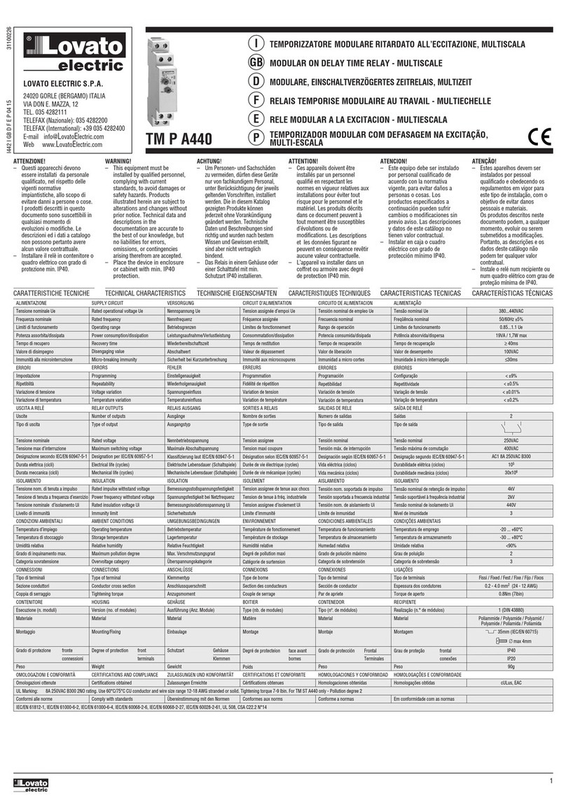
LOVATO ELECTRIC TM P A440 User manual

LOVATO ELECTRIC

LOVATO ELECTRIC TM P A440 User manual

LOVATO ELECTRIC SRB Series Instruction Manual

LOVATO ELECTRIC

LOVATO ELECTRIC SRB Series Instruction Manual

LOVATO ELECTRIC PMA40 User manual

LOVATO ELECTRIC

LOVATO ELECTRIC PMA40 User manual

LOVATO ELECTRIC PMA30 User manual

LOVATO ELECTRIC

LOVATO ELECTRIC PMA30 User manual

LOVATO ELECTRIC EXP10 02 User manual

LOVATO ELECTRIC

LOVATO ELECTRIC EXP10 02 User manual

Popular Relay manuals by other brands

DOLD SAFEMASTER BG 5933 Series Datasheet / Operating Instructions

DOLD

DOLD SAFEMASTER BG 5933 Series Datasheet / Operating Instructions

Zander Aachen SR7C User information

Zander Aachen

Zander Aachen SR7C User information

Tridonic DALI RM CDM 30 10A 1CH manual

Tridonic

Tridonic DALI RM CDM 30 10A 1CH manual

Niko 10-830 manual

Niko

Niko 10-830 manual

Autonics ABL Series quick start guide

Autonics

Autonics ABL Series quick start guide

Siemens 7SR210 Argus quick start guide

Siemens

Siemens 7SR210 Argus quick start guide

Metz Connect C Logline MARK-E08 Mounting Note

Metz Connect

Metz Connect C Logline MARK-E08 Mounting Note

MRS Toggle Relay M3 12 V operating instructions

MRS

MRS Toggle Relay M3 12 V operating instructions

Thytronic SSG instruction manual

Thytronic

Thytronic SSG instruction manual

GE 845 instruction manual

GE

GE 845 instruction manual

ABB COQ Instruction leaflet

ABB

ABB COQ Instruction leaflet

Gira System 3000 operating instructions

Gira

Gira System 3000 operating instructions

Paradyne FrameSaver 9120 user guide

Paradyne

Paradyne FrameSaver 9120 user guide

schmersal PROTECT SRB 200EXi-1R Mounting and wiring instructions

schmersal

schmersal PROTECT SRB 200EXi-1R Mounting and wiring instructions

ABB HCB-1 Instruction leaflet

ABB

ABB HCB-1 Instruction leaflet

Eaton ESR5-BWS-31-24VAC-DC manual

Eaton

Eaton ESR5-BWS-31-24VAC-DC manual

Delixi JRS1Dsp Series user manual

Delixi

Delixi JRS1Dsp Series user manual

GE CHC12A instructions

GE

GE CHC12A instructions

manuals.online logo
manuals.online logoBrands
  • About & Mission
  • Contact us
  • Privacy Policy
  • Terms and Conditions

Copyright 2025 Manuals.Online. All Rights Reserved.