3
I
op
= (CT ratio) x (
I
r
+ n
I
e
)
Ir<(Iop - nIe)
CT ratio
I
e<1x (
I
op -
I
r)
CT ration
protection, it is considered good
practice by some utilities to set the
minimum primary operating current
in excess of the rated load. Thus, if
one of the current transformers
becomes open circuit the high
impedance relay does not
maloperate. The MVTP11/31
(busbar supervision relay) should
give an alarm for open circuit
conditions but will not stop a
maloperation if the relay is set below
rated load.
In the case of the high impedance
relay, the operating current is
adjustable in discrete steps. The
primary operating current (Iop) will be
a function of the current transformer
ratio, the relay operating current (Ir),
the number of current transformers in
parallel with a relay element (n) and
the magnetising current of each
current transformer (Ie) at the stability
voltage (Vs). This relationship can be
expressed in three ways:
To determine the maximum current
transformer magnetising current to
achieve a specific primary operating
current with a particular relay
operating current.
Vs > If(RCT + 2RL) 1
Vs > 1.25If(RCT + 2RL) 2
where RCT = current transformer
secondary winding
resistance
RL= maximum lead
resistance from the
current transformer to
the common point
Note:
When high impedance differential
protection is applied to motors or
reactors, the external fault current
will be low. Therefore, the locked
rotor current or starting current of
the motor, or reactor inrush current,
should be used in place of the
external fault current.
To ensure satisfactory operation of
the relay under internal fault
conditions the current transformer
kneepoint voltage should not be less
than twice the relay voltage setting
i.e. VK≥2VSfor the MCAG/MFAC
and 1.6VSfor the MCTI.
The kneepoint voltage of a current
transformer marks the upper limit of
the roughly linear portion of the
secondary winding excitation
characteristic and is defined exactly
in British practice as that point on
the excitation curve where a 10%
increase in exciting voltage
produces a 50% increase in
exciting current.
The current transformers should be
of equal ratio, of similar
magnetising characteristics and of
low reactance construction. In cases
where low reactance current
transformers are not available and
high reactance ones must be used.
It is essential to use in the
calculations for the voltage setting,
the reactance of the current
transformer and express the current
transformer impedance as a
complex number in the form
RCT + jXCT. It is also necessary to
ensure that the exciting impedance
of the current transformer is large in
comparison with its secondary
ohmic impedance at the relay
setting voltage.
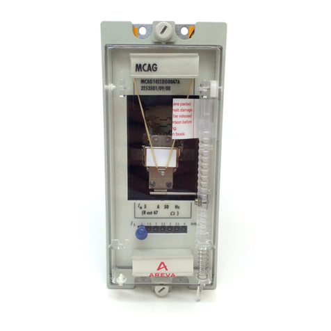
The MCAG14/34
The MCAG14/34 is an
electromechanical current
calibrated relay with setting ranges
of:
0.025 - 0.100A
0.050 - 0.200A
0.100 - 0.400A
0.200 - 0.800A
0.250 - 1.00A
0.500 - 2.00A
1.00 - 4.00A
The relay has a fixed burden of
approximately 1VA at setting current
and its impedance varies with the
setting current used. To comply with
the definition for a high impedance
relay, it is necessary, in most
applications, to utilise an externally
mounted stabilising resistor in series
with the relay coil.
The standard ratings of the stabilising
resistors normally supplied with the
relay are 470Ω, 220Ωand 47Ωfor
0.5A, 1A and 5A current transformer
secondary respectively. In
applications such as busbar
protection, where higher values of
stabilising resistor are often required
to obtain the desired relay voltage
setting, non-standard resistor values
can be supplied. The standard
resistors are wire wound, continuously
adjustable and have a continuous
rating of 145W.
The MCTI14/34
The MCTI14/34 is an electronic
instantaneous overcurrent relay
suitable for high impedance
circulating current protection. The
MCTI14 single phase earth fault relay
or MCTI34 three phase relay, when
used with a stabilising resistor is
designed for applications where
sensitive settings with stability on
heavy through faults are required. The
setting ranges available are as
follows;
5% to 322.5%In in 2.5% steps (K=1)
50% to 3225%In in 25% steps (K=10)
Applying the MCAG14/34 &
MCTI14/34
The recommended relay current setting
for restricted earth fault protection is
usually determined by the minimum
fault current available for operation of
the relay and whenever possible it
should not be greater than 30% of the
minimum fault level. For busbar
To determine the maximum relay
current setting to achieve a specific
primary operating current with a
given current transformer
magnetising current
To express the protection primary
operating current for a particular
relay operating current and with a
particular level of magnetising
current.
In order to achieve the required
primary operating current with the
current transformers that are used, a
current setting (Ir) must be selected
for the high impedance relay, as
detailed in the second expression
above. The setting of the stabilising
resistor (RST) must be calculated in
the following manner, where the
setting is a function of the relay
ohmic impedance at setting (Rr), the
