i-PRO WJ-NX400K User manual

Before attempting to connect or operate this product,
please read these instructions carefully and save this manual for future use.
The model number is abbreviated in some descriptions in this manual.
Installation Guide
Network Disk Recorder
Model No. WJ-NX400K
WJ-NX400K/G
Network Disk Recorder WJ-NX400
123456789
The Operating Instructions (PDF) is on our support website
(https://i-pro.com/global/en/surveillance/documentation_database).

2
Contents
Introduction.............................................................................................................................. 4
Standard accessories ............................................................................................................................................................... 4
About the user manuals ............................................................................................................................................................4
About HDD Unit ........................................................................................................................................................................5
About Additional Camera Kit (option) .......................................................................................................................................5
About Secure Communication Kit (option)................................................................................................................................5
Precautions for installation........................................................................................................................................................5
Basic operations .......................................................................................................................................................................7
Setup menu...............................................................................................................................................................................9
Operations flow ..................................................................................................................... 10
1 Obtain the license (Registration Key) ............................................................................. 12
2 Rack mounting .................................................................................................................. 13
Installation procedure..............................................................................................................................................................13
Position in the Rack ................................................................................................................................................................14
3 Connections ...................................................................................................................... 15
Connection of cameras and a mouse .....................................................................................................................................15
Connection of monitors ..........................................................................................................................................................16
Connection of a PC.................................................................................................................................................................17
Connection of extension units ................................................................................................................................................19
How to use the terminals of the ALARM/CONTROL ..............................................................................................................20
How to use the terminals of the ALARM IN ............................................................................................................................ 24
Time and polarities of the ALARM/CONTROL connector.......................................................................................................26
4 Turn on the devices........................................................................................................... 27
Turn on the power of the recorder ..........................................................................................................................................27
(When turn off the power of the recorder)...............................................................................................................................28
5 Register the license (Registration Key) .......................................................................... 29
6 Assemble HDD unit........................................................................................................... 31
7 Installation of HDD unit .................................................................................................... 32
Install HDD unit in recorder ..................................................................................................................................................... 32
Install HDD unit in extension unit ............................................................................................................................................ 33
Initialize the HDD unit..............................................................................................................................................................34
8 Configure the minimum settings [Easy Start] ................................................................ 35
Troubleshooting..................................................................................................................... 38

Important Information
Refer to the Important Information (PDF) in the provided CD-ROM for the following items.
Safety Information · Important safety instructions
Introduction · Preface · System requirements for a PC
· Network security
Precautions · Precautions for use
Major operating controls · Major operating controls and their functions
User management · User/Host management
HDD unit · Handle the HDD units
· Remove the HDD units from recorder
Others · Troubleshooting
· Specifications
Operating Instructions
Refer to the Operating Instructions (PDF) on our support website for the following items.
Setup via recorder's main
monitor
· Basic setup
Set up date & time and language [Date/Language]
Camera setup [Camera]
Set up recording/events [REC & event]
· Advanced setup
Configure the settings relating to monitors [Monitor]
Configure the settings relating to network [Network]
Configure the settings relating to the user management [User management]
Configure the settings relating to maintenance [Maintenance]
Manage the hard disk drives [HDD management]
Configure the settings relating to the extra functions [Extra function]
· Lists of the setting items
Operation via recorder's main
monitor
· Monitor live images
Operate the camera
· Event function
· Record images
· Play recorded images
· Useful functions
Copy recorded images
Play back copied images with this recorder
Operation via PC web browser · Monitor live images
Operate the camera
· Event function
· Play recorded images
· Copy and download
Copy recorded images
Download
Play back the copied/downloaded images on a PC
· Setup
3
Contents (continued)

4
Introduction
About the user manuals
There are 4 manuals provided for the WJ-NX400K, WJ-NX400K/G as follows.
Installation Guide (this book): Contains procedures of how to install/connect this product with devices and
descriptions about "Easy Start".
Important Information (PDF): Contains preface, precautions, and major operating controls and their functions and
specifications.
Operating Instructions (PDF): Contains descriptions of how to configure the required settings and how to operate
this product.
Refer to our support website
(https://i-pro.com/global/en/surveillance/documentation_database).
Quick Reference Guide: Contains descriptions of how to operate functions frequently used.
Adobe®Reader®is required to read the PDF files (the setup instructions and the operating instructions) on the provided CD-ROM.
When Adobe®Reader®is not installed on the PC, download the latest Adobe®Reader®from the Adobe web site and install it.
"NX400" shown in the instructions and illustrations used in these operating instructions indicate the WJ-NX400K, WJ-NX400K/G.
The screens used in these operating instructions show the case of NTSC model.
Refer to "readme.txt" on the provided CD-ROM for further information about the optional dedicated software, compatible network
cameras (hereinafter, cameras) and their versions.
Refer to our support website (https://i-pro.com/global/en/surveillance/training_support/support/technical_information) for latest
information about the compatible cameras and functions to be added or changed by firmware upgrade.
The external appearance in the document may differ from the actual product within no influence range on operation due to
improvement of the product.
CD-ROM*1.................................................................................................1 pc.
Mouse ........................................................................................................1 pc.
Installation Guide (this book) ......................................................................1 pc.
Quick Reference Guide...............................................................................1 pc.
Activation Key Card ....................................................................................1 pc.
Terminal Plug (12 pin) .................................................................................2 pcs.
Terminal Plug (16 pin) .................................................................................2 pcs.
Cable Clamp (for fixing cable connected to Terminal Plug)..........................1 pc.
Dust caps for the front USBs*2...................................................................2 pcs.
Power cord (WJ-NX400K) ..........................................................................1 pc.
Power cord (WJ-NX400K/G).......................................................................2 pcs.
Key.............................................................................................................2 pcs.
Label*3.......................................................................................................1 pc.
Rack mounting bracket ..............................................................................2 pcs.
Rack mounting bracket fixing screw ...........................................................6 pcs.
Rack handle ...............................................................................................2 pcs.
Screws for the rack handle .........................................................................4 pcs.
Washer.......................................................................................................4 pcs.
HDD canister..............................................................................................9 pcs.
HDD fixing screw........................................................................................54 pcs.
Power cord clamp ......................................................................................1 pc.
*1 The CD-ROM contains the operating instructions (PDFs). Make sure to read them when installing or setting the recorder.
*2 Put the dust caps for the front USBs on the front copy port and mouse connection port to prevent dust brought by fan's
intake while you are not using a mouse or an external storage device.
*3 This label is the same one found on the surface of this product. Keep it in view when installing this product in the rack.
Standard accessories

5
Introduction (continued)
About Additional Camera Kit (option)
Number of cameras to be used in the system (64 cameras in basic system) can be increased to 96 and 128 (maximum) by
purchasing the Additional Camera Kit (WJ-NXE40, WJ-NXE40W: option). Refer to following table regarding camera numbers.
Additional Camera Kit
WJ-NXE40, WJ-NXE40W
(license for 32 cameras)
NX400 only
(No additional license)
one Additional Camera Kit
(one additional license)
two Additional Camera Kit
(two additional licenses)
up to 64 cameras up to 96 cameras up to 128 cameras
Important:
• The following functions are not available when registering the additional camera kit license.
∙ Display of the camera image on the main and the sub monitors connected to the recorder
* Camera images will be displayed on the web browser of the personal computer (hereinafter, PC), but not on the main or
sub monitor.
∙ Display, search, playback and copy of the recorded image on the main monitor connected to the recorder
∙ Sub-stream recording
∙ Re-encoding transmission
∙ A part of setup menu operation
* The main monitor displays not a camera image but a special menu. The sub monitors turn black.
About HDD Unit
To install a hard disk drive in the recorder, it is necessary to assemble an HDD unit (encase the hard disk drive in the HDD canis-
ter). The HDD unit is designed to easily install/remove the hard disk drive in/from the recorder. Contact your dealer about pur-
chasing, installing, and replacing the hard disk drives.
This product is designed to be used indoors.
i-PRO Co., Ltd. assumes no responsibility for injuries
or property damage resulting from failures arising out
of improper installation or operation inconsistent with
this documentation.
Do not place this product in the following places:
• Locations exposed to direct sunlight
• Locations subject to having strong vibration or impact
• Locations near magnetic field sources such as a televi-
sion or speakers
• Locations near the devices that emit large sound and
generate vibration by sound pressure
Precautions for installation
Registering a license of a secure communication kit (option) to the recorder enables secure communication with cameras. Each
secure communication kit differs in the number of cameras that can be registered as shown in the table below. Use several
licenses as necessary.
WJ-NXS01, WJ-NXS01W WJ-NXS04, WJ-NXS04W WJ-NXS16, WJ-NXS16W WJ-NXS32, WJ-NXS32W
1 camera 4 cameras 16 cameras 32 cameras
About Secure Communication Kit (option)

6
Introduction (continued)
• Locations where condensation forms easily, where tem-
perature changes greatly or where humidity level is high
• Locations subject to steam and oil smoke such as a
kitchen
• Locations which are not level
• Locations subject to dust
• Locations where it may get wet from rain or water splash
Do not install this product in locations where the
product or the cables can be destroyed or damaged
by persons with malicious intent.
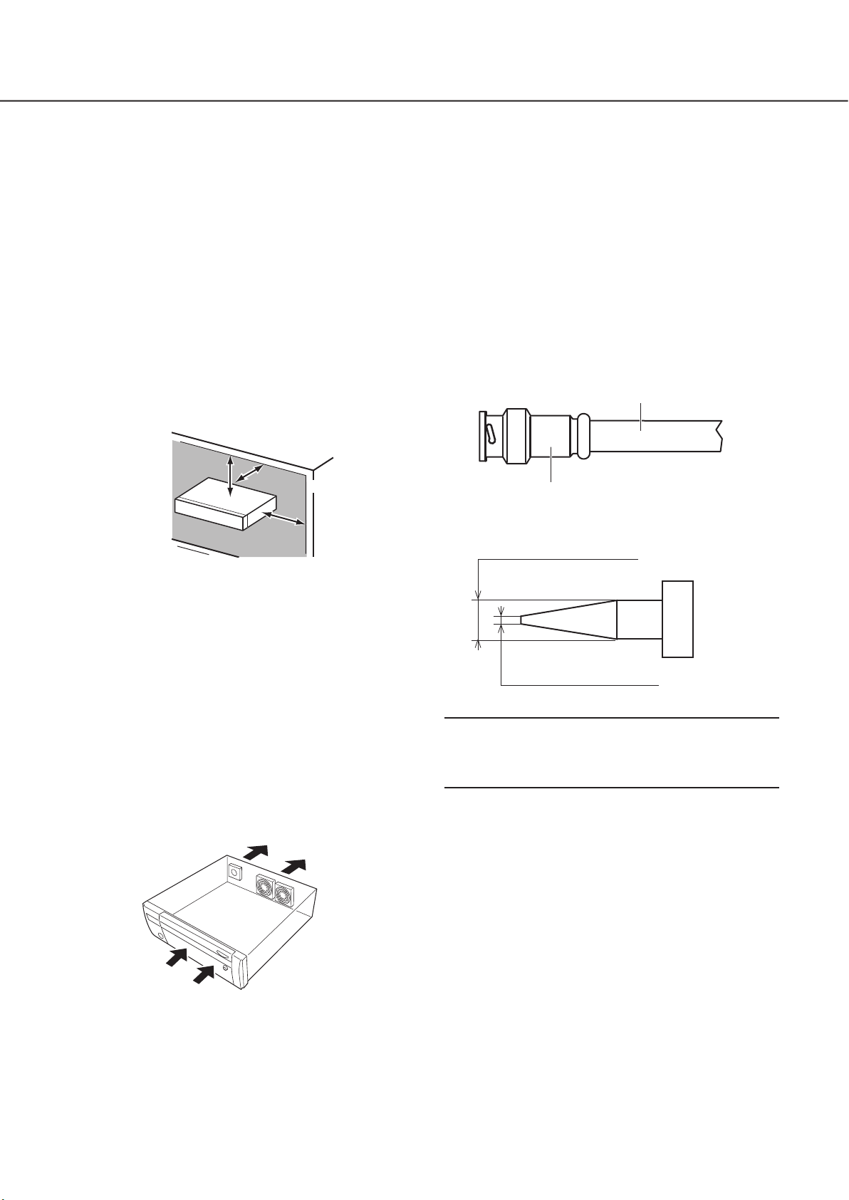
Place this product horizontally on a level surface.
Do not place this product in an upright position. When
stacking multiple recorders, clear a space of more than 5 cm
{2 inches} from both sides, the top, the bottom and the rear
of the recorders.
More than
5 cm {2 inches} More than
5 cm {2 inches}
More than
5 cm {2 inches}
Heat dissipation
To prevent this product from overheating, heed the follow-
ing. Failure to observe this may cause fire or trouble.
• Do not block the cooling fan outlet or the ventilation holes
with a wall, rack, cloth, etc. Maintain the product periodi-
cally to prevent dust from blocking ventilation holes.
• The lifetime of the cooling fan is limited by use. It is rec-
ommended to replace them after around 30000 hours of
operation. Contact your dealer for replacement of the
cooling fans.
• Clear a space of more than 5 cm {2 inches} from both
sides, the top, and the rear of the product. Do not block
the ventilation holes on the front side since this product
is designed to cool the hard disk drives by drawing in air
from the front.
Avoid placing this product near noise sources
If the cables are placed near noise sources such as fluores-
cent lamps, noises may be produced. In this case, rewire
avoiding the noise sources, or move the product to a place
far from the source.
Grounding
Confirm that the wire is connected from the SIGNAL GND
terminal to earth ground.
A grounding connection must be made before connecting
the power plug or this product to the main power supply.
When disconnecting the grounding wire, make sure that the
power plug of this product is disconnected from the main
power supply.
For BNC cable connection
Use only the recommended plug below when connecting the
BNC plug to the connectors on the rear panel of this product.
Applicable plug: MIL-C39012C, MIL-C39012/16F or BS
CECC2212: 1981
* Suffixes attached to the standards may be updated.
BNC cable (locally procured)
Plug (locally procured)
Tip dimensions inside the recommended BNC plug
ø1.32 mm - ø1.37 mm
{ø0.052 inches - ø0.054 inches}
ø0.13 mm - ø0.69 mm
{ø0.005 inches - ø0.027 inches}
Important:
• A compatible plug shall be used. Failure to observe this
may cause trouble such as poor contact. At worst, the
connector of this product may be damaged.
Avoid placing receptacles that contain liquids such as
water near this product.
If liquid spills onto this product, it may cause fire or an elec-
tric shock.
Shielded (STP) LAN cables must be used with this unit
to ensure compliance with EMC standards.
About sulfuration of rubber products
Do not leave rubber products containing sulfur (packing and
rubber feet) close to the recorder or in the same storing box.
Sulfur constituent from the rubber products may cause sul-
furation corrosion on electrical parts or terminals and defects
in the recorder.

7
Display method of the setting screen
Click the [Setup] button.
The top screen of the setup menu will be displayed.
Connection of a mouse
Connect the provided mouse to the mouse connection port
on the rear side of the recorder.
The mouse cursor will be displayed on the main monitor.
Mouse operation
Left-click the desired buttons and tabs on the screen.
(Hereinafter, "Left-click..." will be described as "Click..." in
this document.)
When the entry field has the [▲] and [▼] buttons or the [▼]
button, the setting value can be changed using the mouse
wheel.
When no operation is made for 10 seconds or more, the
mouse cursor will be hidden. The mouse cursor will be dis-
played again when the mouse is moved.
This section explains operation of a mouse and the soft keyboard, and setting screen only.
The recorder can be operated using the mouse (provided) connected to the mouse connection port either on the front or the rear
side of the recorder.
It is also possible to perform settings and some operations of the recorder from the web browser. Refer to the Operating
Instructions (PDF) for descriptions of how to operate from the web browser and the configurable settings using the web browser.
Basic operations
Introduction (continued)

8
About the operation of on-screen keyboard
Use the on-screen keyboard to enter characters for the setting items. When clicking the [ ] icon beside the entry field, the on-
screen keyboard will be displayed, and it will become possible to enter characters by clicking the character keys on the key-
board.
On-screen keyboard screen
[Del all] button
Deletes all the characters in the entry field.
[]/[] button
Move the cursor in the entry field to either direction.
[Delete] button
Deletes a character pointed by the cursor in the entry field.
[A/a] button
This button changes the characters to be entered between
capital letters and small letters.
[Next] button
Changes the keys to be displayed for character entry.
The displayed keys are changed as follows:
Keys for the language selected by the language selec-
tion pull-down menu Combination characters
Special characters
[Enter] button
Determines the entered characters and closes the on-screen
keyboard.
Note:
• Basic operations are also applied to the "Login" window
and registration window for license.
• Click the [×] button to close the window without deter-
mining the entered characters.
Entry field
Language selection pull-down menu
Click the [▼] button to select the language
for character entry.
Introduction (continued)

9
Configuration of each setting item in the setup menu should be completed in advance to use this recorder.
The setup menu has the following levels for the setting items. On "Easy Start", the minimum settings required to operate the
recorder will be performed, but other settings will remain default. On the [Basic setup] or [Advanced setup] page, the settings can
be customized in accordance with a variety of operational modes.
The following is the example of the setup menu that describes the features and operations.
The setup menu will be displayed when clicking the [Setup] button (☞Page 7) at the upper right corner of the operational screen
on the main monitor.
The buttons of the setup pages will be displayed on the left column of the setup menu.
Setup menu
➀[Home] button
It is possible to return to the top screen (☞Page 7) of
the setup menu from any setup page.
➁Setup menu panel
Displays buttons of the setup pages.
➂[Easy Start] button
It is possible to configure the minimum settings required
to operate the recorder, such as date & time and cam-
era registration.
➃[Basic setup] – Setup page buttons
Each "Basic setup" page will be displayed.
➄[Advanced setup] button
The buttons to open the corresponding setup pages of
the "Advanced setup" menu will be displayed. When
clicking this button again, the buttons will be hidden.
➅[Advanced setup] – Setup page buttons
Each "Advanced setup" page will be displayed.
➆Hierarchical display
The name of the current setup page will be displayed in
the hierarchy. The tab name will also be included.
➇Setup page
Displays each setup page. If the current setup page is
composed of two or more tabs, it is possible to change
the page display by clicking the tabs.
➈[Exit] button
Applies the settings to the recorder and closes the setup
menu to return to the operational screen (☞Page 11).
Except for some cases, the descriptions of this document
follow the hierarchical display and setup pages.
Important:
• If the settings are applied, all login users will be forcibly
logged out.
Introduction (continued)

10
1Obtain the license (Registration Key)
☞Page 12 and Activation Key Card
2Rack mounting
☞Page 13
3Connections
☞Page 15
4Turn on the devices
☞Page 27
5Register the license (Registration Key)
☞Page 29
6Assemble HDD unit
☞Page 31
Obtain the "Registration Key" of the recorder by following the
instructions on the provided Activation Key Card. To
increase the number of connected cameras or use the
secure function, get the registration key of the additional
license according to the appropriate Additional Kit (option).
The obtained "Registration Key" will be used in Step 5.
Install the recorder in the rack. (☞Page 13) Go to step 3
when not installing it in the rack.
Connect the recorder to each device.
Turn on the power to launch in the following order.
Turn on the power of the camera and the monitor.
Turn on the power of the extension unit if connected.
Turn on the power of the recorder.
Register the Registration Key of the recorder. If necessary,
register the "Registration Key" for the Additional Camera Kit
or the Secure Communication Kit.
Important:
• Be sure to register the "Registration Key" of the recorder.
If the "Registration key" of the recorder is not registered,
the Additional Kit cannot be registered.
After registration, click [Restart] button on the license
registration screen to reboot the recorder and activate the
license.
To install a hard disk drive in the recorder, it is necessary to
assemble an HDD unit (encase the hard disk drive in the
HDD canister).
• Professional knowledge on and experience in network and the HDD are required for
the settings and changes of the operation.
• The main monitor is required for the settings.
* The settings can be done through a web browser on the PC (Refer to the Operating
Instructions (PDF)).
• The PC is required for reading the Important Information, the Operating Instructions
(PDF) and camera settings.
Operations flow

Example of an operational screen
11
7Installation of HDD unit
☞Page 32
8Configure the minimum settings
[Easy Start]
☞Page 35
Setup
☞Operating Instructions
(PDF file on our support
website)
Start operations
Remove the "HDD unit holding bracket" of the recorder and
take out the HDD unit.
The removed "HDD unit holding bracket" is necessary when
transporting the recorder. Keep it in an appropriate place.
Register the date & time and cameras on "Easy Start".
When it is not necessary to change other default settings, it
is possible to start operations.
If necessary, perform the detailed settings for each function.
When the camera image is displayed on the main monitor or
the web browser on the PC and can be recorded or played,
the recorder is ready for operation.
Operations flow (continued)

12
Keep the "Activation Key Card" provided with the recorder nearby.
Obtain the "Registration Key" of the recorder by following the instructions on the provided Activation Key Card.
To increase number of connected cameras, get the registration key number of the additional camera license according to the
Additional Camera Kit (option).
To use the secure function, get the registration key number of the additional secure license according to the Secure
Communication Kit (option).
* Each additional kit is the "Activation Key Card" with "the recorder ID number, activation ID number" for the applicable additional
license.
Note:
• A PC or a mobile phone accessible to the Internet is necessary to acquire the registration key number.
1
Obtain the license (Registration Key)

13
2
Rack mounting
Step 3
Place the provided rack mounting brackets (provided)
on both sides of the recorder and fix them with the
rack mounting bracket fixing screw (provided) (×6).
Secure them using the rack mounting bracket fixing screw
(provided) (×6).
Tightening torque: 0.88 N·m ~ 1.08 N·m (0.65 lbf·ft ~ 0.80 lbf·ft)
Rack mounting bracket fixing screws (provided)
Rack handle (provided)
Rack mounting brackets (provided)
Rack handle (provided)
Step 4
Install the recorder in the rack by using four rack
mounting screws.
Secure using the rack mounting screws (×4).
Tightening torque: 2.0 N·m ~ 2.4 N·m (1.48 lbf·ft ~ 1.78 lbf·ft)
Rack mounting screws (M5 x 12, locally procured)
Important:
• When installing the recorder in the rack, make a space
of 1U (44 mm {1-23/32 inches}) above and below the
recorder for ventilation.
• Keep the temperature in the rack below +45 °C {113 °F}.
• It is recommended to install cooling fans or equivalents to
keep the temperature in the rack below +30 °C {86 °F}.
• Do not block the ventilation holes or slots to prevent the
recorder from overheating.
• The recorder weighs over 10 kg{22.1 lbs}. Be careful
not to drop the recorder when installing it into a rack.
Dropping may cause damage, deformation of the
recorder, or injury.
Install the recorder in an EIA standard 19-inch rack (Depth:
550 mm or more).
Note:
• Use four M5 × 12 screws (locally procured) to install the
recorder in a rack.
• The illustration on this page is schematic. Details of the
shape are omitted.
Installation procedure
Step 1
Remove the five rubber feet from the bottom of the
recorder using a flathead screwdriver.
Use a screwdriver to remove the screws holding the rubber feet.
Remove rubber feet
Step 2
Attach the rack handles (provided) to the rack mount-
ing brackets (provided).
Fix them using the screws (provided) (×4) and the washers
(provided) (×4) for the rack handle.
Tightening torque: 2.0 N·m ~ 2.4 N·m (1.48 lbf·ft ~ 1.78 lbf·ft)
Washer (provided)
Screws for the rack handle (provided)
Rack mounting bracket (provided)
Washer (provided)
Rack handle (provided)
Note:
• The rack mounting bracket (provided) has two types of
fitting holes to adjust the protrusion of the front rack. Use
either of them depending on the installation conditions.
Standard fitting holes
Fitting holes for the front position (about 15 mm {19/32 inches})

14
Position in the Rack
This is an example where the recorder and the extension unit (WJ-HXE400, max 5 units) are installed in the rack.
Connect the recorder and the extension unit using the connection cable (1.5 m {4 feet 11 inches}) provided with the extension unit.
(☞Page 19)
NX400
Require a space of 1 unit
Connection cable
(provided with extension unit)
Extension unit
(Unit number 1)
Extension unit
(Unit number 2)
Extension unit
(Unit number 3)
Extension unit
(Unit number 4)
Extension unit
(Unit number 5)
Other unit, Rack upper side
Other unit, Rack bottom side
Require a space of 1 unit
Note:
• When installing the recorder in the rack, leave a space of 1U (44 mm {1-23/32 inches}) above and below the recorder for ventila-
tion.
• The unit number of the connected extension unit is the same as the external storage connector number of the recorder.
2
Rack mounting (continued)

15
3
Connections
Connection of cameras and a mouse
Up to 128 cameras can be connected to the recorder via a switching hub.
Connect to the Camera/PC port of the recorder.
Use a Ethernet cable (straight) to connect the recorder and the switching hub.
Connect the provided mouse to the mouse connection port on the front or rear side of the recorder.
Recorder
Ethernet cable (locally procured):
category 5e or better (straight) for
WJ-NX400K, category 7 (straight) for
WJ-NX400K/G
Mouse (provided)
PoE hub
Network camera (x 128 max.)
(When 2 licenses are used for the additional camera kit)
Note:
• Make sure to use the wired network to connect with the recorder even for the cameras equipped with the wireless LAN func-
tion.

16
Connection of monitors
Connect a main monitor (to be used to display live images, recorded images or the setup menu) and a sub monitor (to be used
to display live images only) to the HDMI (video/audio output) connectors using HDMI cables (optional). Connect a sub monitor
(BNC) to the video output connector using a BNC cable (locally procured).
Recorder
BNC cable (locally procured)
Audio cable
(option)
HDMI cable
(option)
Powered speaker
Sub monitor (BNC)
Main monitor (HDMI)
HDMI cable (option)
* When outputting audio
Connect a powered
speaker.
Sub monitor (HDMI)
Important:
• If the additional camera license is not registered, the main or sub monitor displays image of a channel (from 1 to 64 channel).
• When the additional camera license is registered, the image will be displayed only on the web browser of the PC. The main
and sub monitors go black and do not display the image.
Note:
• Use "High Speed HDMI®Cable". When the main monitor is used in 4K/25P(30P), use a 10.2 Gbps compatible HDMI cable.
• To maintain the stable performance without deteriorating the image quality, use an HDMI cable whose length is 5 m {16 feet
5 inches} or less.
• Audio will be output from the monitor when the monitor is connected with an HDMI cable.
• Same audio output from the main monitor will be heard from the speaker connected with an audio cable.
• No audio will be heard from the sub monitor (HDMI) connected with an HDMI cable.
3
Connections (continued)

17
Connection of a PC
Connect this recorder and a PC via a switching hub.
When PC and the camera are in the same network
When the PC and the camera are configured on the same network, connect the PC to the Camera/PC port.
Recorder
Network
PoE hub
Network camera (x 128 max.)
(When 2 licenses are used for the additional camera kit)
PC
IP address: 192.168.0.250
Subnet mask: 255.255.255.0
Default gateway: 192.168.0.1
Ethernet cable (locally procured):
category 5e or better (straight) for
WJ-NX400K, category 7 (straight) for
WJ-NX400K/G
IP address: 192.168.0.1
Subnet mask: 255.255.255.0
IP address: 192.168.0.x
(except 0, 1, 250 and 255)
Subnet mask: 255.255.255.0
Default gateway: 192.168.0.1
3
Connections (continued)

18
When PC and the camera are in different networks
When the PC and the camera are configured on different networks, connect the PC to the PC port.
Recorder
Network
PoE hub
Switching hub
Network camera (x 128 max.)
(When 2 licenses are used for the additional camera kit)
Ethernet cable (locally procured):
category 5e or better (straight) for
WJ-NX400K, category 7 (straight) for
WJ-NX400K/G
Ethernet cable (locally procured):
category 5e or better (straight) for
WJ-NX400K, category 7 (straight) for
WJ-NX400K/G
[Camera/PC port]
IP address: 192.168.0.250
Subnet mask: 255.255.255.0
Default gateway: 192.168.1.1
[PC port]
IP address: 192.168.1.250
Subnet mask: 255.255.255.0
PC
IP address: 192.168.1.x
(except 0, 1, 250 and 255)
Subnet mask: 255.255.255.0
Default gateway: 192.168.1.1
Note:
• Cameras shall be connected to the camera/PC port. If the camera is connected to the PC port, the camera will not be
detected automatically.
3
Connections (continued)

19
Connection of extension units
Up to 5 extension units (WJ-HXE400: optional) can be connected with a single network disk recorder. Connect the recorder and
the extension unit using the connection cable provided with the extension unit. Connect the extension units as shown in the illus-
tration below. Refer also to the operating instructions of the extension unit.
45 1
23
Fix the connection cable
Connection cable
(provided with extension unit)
Network disk recorder
Extension unit (unit number 1)
Extension unit (unit number 2)
Extension unit (unit number 3)
Extension unit (unit number 4)
Extension unit (unit number 5)
Attach a cable clamp to each connection
cable.
Attach a cable clamp to each connection
cable.
Important:
• Use only the dedicated connection cable provided with the extension unit when connecting the recorder and the extension
unit.
• Fix the connection cable firmly using the cable clamp provided with the extension unit. When the cable is not connected
firmly or when it is disconnected, the system may become unstable or recording may fail.
Refer to the operating instructions of the extension unit for details on how to fit the cable clamp.
• Do not wind the cable in a coil.
3
Connections (continued)

20
How to use the terminals of the ALARM/CONTROL
The ALARM/CONTROL connectors on the back is used when connecting an external device such as a sensor that outputs alarm
signals or when installing an external alarm device such as a buzzer or a lamp outside.
Insert the unarmored cable into the provided terminal plug (12 pin) and then mount it on the ALARM/CONTROL connector on the
back.
* The cable should be a single or twisted wire with AWG 26~16 and an exposed length of 9 mm {11/32 inches}.
ALARM/CONTROL
connector on the back
D1 C1
D12
ALARM/CONTROL
C12
Cable connections
Tight the screw when the cable is
fully inserted into the terminal hole.
Loosen the screw of the desired
terminal on the terminal plug.
Mount the terminal plug with the
cable connected on the ALARM/
CONTROL connector socket on
the back.
Terminal plug (12 pin)
C1 (D1) side
Pin array
Pin No. Signal Operation Remarks
C1 Alarm output 1
Alarm signal will be supplied at an event occurrence
Open collector output
24 V DC max., –200 mA max.
C2 Alarm output 2
Alarm signal will be supplied at an event occurrence
C3 Alarm output 3
Alarm signal will be supplied at an event occurrence
C4 Alarm output 4
Alarm signal will be supplied at an event occurrence
C5 Time adjustment I/O According to the signal input from the other device,
the time of the recorder will be adjusted to the hour
based on the input time
In addition, the signal is output at the setting time
of the recorder and the time of other equipment is
adjusted to the time of the recorder
Input:
Non-voltage make contact input
Output:
Open collector output
24 V DC max., –200 mA max.
C6
Preliminary Input/Output 1
These are for future input and output, and cannot
be used
C7
Preliminary Input/Output 2
C8
Preliminary Input/Output 3
C9
Preliminary Input/Output 4
C10 +5 V output +5 V output +5 V±0.5 V, 200 mA max.
C11 Signal ground
C12 Signal ground
D1 Alarm reset input Canceling the alarm display Non-voltage make contact input
D2 Emergency recording
input
Starting emergency recording signal input
D3
Outage detection input
Start of outage processing according to the signal
input
D4
External recording
mode switching input
Changeover to the external recording mode by
the signal input
D5 Network error output A signal will be output upon detection of a discon-
nected Ethernet link or IP expiration of the DHCP
Open collector output
24 V DC max., –200 mA max.
D6 HDD error output Signal output upon detection of an HDD error
D7 Camera error output Signal output upon detection of a camera error
D8
Recording error output
Signal output upon detection of a recording error
D9 Recorder error output Signal output upon detection of a recorder error
D10 Outage processing
end output
Signal output upon completion of outage pro-
cessing
High (ON) 5 V DC
Low (OFF) 0 V DC
D11 Signal ground
D12 Signal ground
* Refer to the "About the error logs and the network logs" (☞Operating Instructions (PDF)) for further information about each
error output.
3
Connections (continued)
This manual suits for next models
1
Table of contents
Other i-PRO Tuner manuals