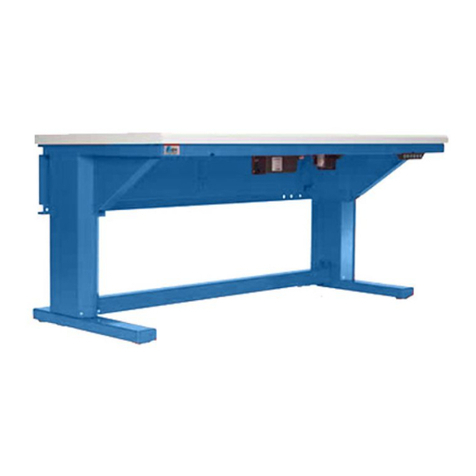
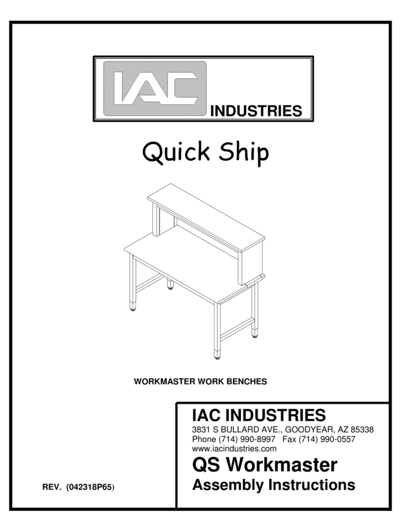
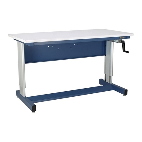
IAC INDUSTRIES Quick Ship ISLES WORKMASTER User manual

INDUSTRIES
Quick Ship
Rev (092105)
ISLES WORKMASTER
Assembly Instructions
IAC INDUSTRIES
895 BEACON STREET BREA, CA 92821-2926
Phone (714) 990-8997 Fax (714) 990-0557
www.iacindustries.com

PRE ASSEMBLY INSTRUCTIONS
Your bench has been carefully packed at the factory to prevent damage
during shipment. Unpack all parts and examine them for damage. Contact
your freight carrier for freight claims information if your order was
shipped "freight collect" or "pre-pay and add". Contact IAC Industries at
800 989-1422 if parts are missing.
PRE-ASSEMBLY PARTS CHECK:
HARDWARE TEMPLATE:
Item #1 Item #2 Item #3 Item # 11
1/4-20x3/4" Hex Head Bolt 1/4" Flat Washer 5/16-18x3/4" Hex Head Bolt Beam Connector Plate
(Includes lock washer) (Includes lock washer)
Item Description Qty Item Description Qty
1 1/4-20x3/4" Hex Head Bolt 16 6 Support Beams 2
2 1/4" Flat Washer 24 7 Leg Extenders (See Page 5) 4
3 5/16-18x3/4" Hex Head Bolt 8 8 Floor Glides (See Page 5) 4
4 Worksurface RFE 1 9 Unistrut Nut or (Footrest Bracket) 2
5 Pedestal Legs 2 10 Footrest (optional) 1
11 Beam Connector Plate 4
TOOLS NEEDED: Power or hand held Phillips screwdriver with #2 tip, 7/16"
and 1/2" combination wrench or thin wall sockets.
2

BASIC BENCH ASSEMBLY INSTRUCTIONS
NOTE: YOU'LL BE WORKING WITH THE LAMINATE SIDE OF THE
WORKSURFACE FACING DOWN. BE SURE TO LAY THE
WORKSURFACE ON A FLAT SMOOTH SURFACE DURING ASSEMBLY
TO AVOID DAMAGING THE WORKSURFACE.
STEP 1 - INSTALL THE SUPPORT BEAMS. (Item 6)
THE BOTTOM OF THE WORK SURFACE HAS THREADED INSERTS INSTALLED
IN IT. NOT ALL OF THESE INSERTS ARE REQUIRED FOR THE ASSEMBLY OF A
BASIC BENCH. SOME INSERTS ARE FOR MOUNTING OTHER TYPES OF
BENCH FRAMES, DRAWERS, INSTRUMENT SHELVES, AND OTHER
ACCESSORIES.
PLACE THE SIDE OF THE BEAM WITH THE TWO OBLONG SLOTS DOWN ON
THE WORK SURFACE. THESE SLOTS WILL ALIGN WITH TWO THREADED
INSERTS AT THE FRONT AND REAR OF THE WORKSURFACE. THREAD SMALL
HEX HEAD 1/4 -20 X 3/4" BOLTS (Item 1) WITH 1/4“ FLAT WASHERS (Item 2)
THROUGH THE SLOTS AND INTO THE INSERTS IN THE WORKSURFACE.
HAND TIGHTEN THE HARDWARE. (SEE FIGURE 1)
3

STEP 2 - ATTACH BEAM CONNECTOR PLATES AT EACH END OF THE BEAMS.
THREAD THE LARGER HEX HEAD 5/16-18 X 3/4” BOLTS (Item 3) WITH 1/4”
FLAT WASHERS (Item 2) THROUGH THE HOLES AT THE ENDS OF THE BEAMS
A FEW THREADS INTO THE BEAM CONNECTOR PLATES. THESE MUST BE
LOOSE AT THIS TIME. (SEE FIGURE 3)
STEP 3 - INSTALL THE PEDESTAL LEGS. ( Item 5 )
THE PEDESTAL LEGS HAVE SLOTS AT THE TOP, WHICH WILL FIT OVER THE
BOLTS HOLDING THE BEAM CONNECTOR PLATES TO THE SUPPORT BEAMS.
SLIDE THE LPEDESTAL LEGS OVER THE BOLTS SO THAT THE CONNECTOR
PLATE IS INSIDE THE LEG TUBE. (See Figure 4) TIGHTEN THE BOLTS SO
THEY ARE “SNUG”...DO NOT TIGHTEN COMPLETELY. THERE ARE TWO
INSERTS IN THE WORKSURFACE THAT LINE UP WITH OBLONG SLOTS IN
EACH OF PEDESTAL LEG TOP BRACES. THREAD THE SMALLER HEX HEAD
1/4 -20X3/4 BOLTS (Item 1) WITH 1/4 FLAT WASHERS (Item 2) INTO THE
INSERTS FOR BOTH PEDESTAL LEGS. THE FRAME MUST BE SQUARED UP
ON THE WORKSURFACE (See Figure 2). ONCE THE FRAME IS SQUARED ALL
HARDWARE MUST BE TIGHTENED COMPLETELY. CAUTION: DO NOT OVER
TIGHTEN THE BOLTS ATTACHING THE FRAMES TO THE WORKSURFACE AS
THIS MAY CAUSE DAMAGE TO THE WORKSURFACE.
4
Figure 2

STEP 4 - INSTALL THE LEG EXTENDERS.
INSTALL THE FLOOR GLIDES INCLUDED IN THE HARDWARE KIT INTO THE
BLACK PLASTIC INSERT IN THE END OF THE LEG EXTENDERS. HOLDING
THE LEG EXTENDER BY THE FLOOR GLIDE, PLACE THE EXTENDER INSIDE
OF THE END SECTION PEDESTAL LEGS SO THAT THE ROW OF THREADED
HOLES IN THE SIDE OF THE EXTENDER ALIGN WITH THE TWO HOLES IN THE
INNER PORTION OF EACH LEG. THE EXTENDERS ARE ADJUSTABLE ON TWO-
INCH INCREMENTS. SECURE THE EXTENDERS AT THE DESIRED HEIGHT
WITH TWO OF THE SMALLER HEX HEAD 1/4 -20X3/4 BOLTS (Item 1) WITH 1/4
FLAT WASHERS (Item 2) THREADED INTO EACH LEG EXTENDER. SNUG UP
THE BOLTS, BUT BEFORE TIGHTENING THE BOLTS COMPLETELY, APPLY
DOWNWARD PRESSURE ON THE FLOOR GLIDES TO TAKE ANY PLAY OUT OF
THE EXTENDERS. SMALL ADJUSTMENTS CAN BE MADE WITH THE FLOOR
GLIDES ONCE THE BENCH IS UPRIGHT. (SEE FIGURE 5)
TURN THE BENCH UPRIGHT, MOVE THE BENCH INTO PLACE AND USE THE
FLOOR GLIDES IN THE LEG EXTENDERS TO LEVEL IT.
5

QS SB / WM INSTRUMENT SHELF (HWR 045)
(Refer to FIGURE 6 )
PRE-ASSEMBLY PARTS CHECK:
HARDWARE TEMPLATE:
6

STEP #1- INSTALLING RISER BOXES TO LAMINATE SHELF.
With Laminate shelf still in the shipping box to protect the shelf,
attach Riser boxes to the Laminate Shelf making note that the
Riser Box flange is facing away and out from the shelf and
securing with four (4) sets of 1/4-20x3/4" hex head bolts and flat
washers for each side.
Do not tighten hardware down yet.
NOTE: the side of the riser box with 2 holes and electrical knock
out hole faces toward the back of the bench.
STEP #2- INSTALLING BEAMS TO THE RISER BOXES.
Connect the FRONT SUPPORT BEAM (OR OPTIONAL ELECTRICAL
STRIP (in lieu of beam) as well as the REAR BEAM to the riser
boxes by using four (4) sets of 1/4-20x3/4" hex head bolts, 1/4 flat
washers and 1/4-20 keps nuts on each side (nut is positioned inside
the riser box to secure the bolt. In the case of the optional
electrical strip, only the 1/4-20x3/4" hex head bolts and 1/4 flat
washers are needed) . Tighten hardware from beam to riser boxes
making sure the beams are flush with the Riser boxes (Top & Sides)
to minimums any gaps between the Work surface and the Beams.
Once this is done, secure the Riser boxes to the shelf by tighten
down the hardware from step #1.
PLEASE NOTE: If you are installing optional WM UNDERSHELF
please see page 9 referencing installation of light and install
light at this time.
STEP #3- INSTALLING SHELF TO BENCH.
With two persons ( one on each side ) turn over and attach Riser
Boxes (Support) to the bench by sliding the flange onto the bench
top at the outside rear of the bench. Secure flanges with 1/4-
20x3/4" hex head bolts and flat washers (two on each side) Tighten
down hardware.
7
STEP #4- INSTALLING RISER BOX COVERS.
Push the small end of the rubber, threaded inserts (plastic, 6-32
blind nuts) into each riser box (12 Places) to be used to attach
the riser box covers.
Attach riser box covers to the Riser Boxes using six (6), 6-32x1/2"
Phillips head screws. (See above drawing)
PLEASE NOTE:To align covers panels properly, install two
6-32x1/2" Phillips head screws into the two center holes first.
Then place all the other 6-32x1/2" Phillips head screws into the
other remaining holes to make sure the panels are aligned.
STEP #5- INSTALLING PLASTIC PLUG CAPS.
Insert the three types of black plastic plug caps into the unused
holes using the hardware template and Figure 6 (Page 6) for
proper reference to the installation of plug caps.
8

QS WM UNDERSHELF LIGHT ( HWR 048 )
If you are installing the optional WM UNDERSHELF LIGHT, remove
the plastic diffuser cover. Attach light casing to the 2 pre-
drilled holes in the underside of the shelf using the 2 sets of 1/4-
20X5/8” Phillips screws and the 2 flat washers provided in
Hardware Kit # 048.
9

ESD GROUNDING (Bench HWR 014, Instr. Shelf HWR 122, Personnel Grd HWR 019. )
ESD refers to the OPTIONAL static dissipative laminate used on the bench. The
laminate has a conductive layer that comes in contact with the factory
installed grounding bolts in the worksurface. The ESD grounding kit, including
the 10 ft. grounding wire must be attached and the bench must be properly
grounded to your facility earth ground. (See below for grounding cautions!)
The eyelet slips over the bolt end and the alligator clip attaches to ground.
When tested with a megohmmeter the ground bolts should measure 1 (1x10⁶) to
1000 (1x10⁹) in accordance with EOS/ESD standards prescribed in EOS/ESD
document S4.1-1990 Worksurfaces-Resistive Characterization. For specific
details on grounding the bench consult EOS/ESD document S6.1-1991 Grounding
- Recommended Practice.
GROUNDING CAUTIONS:
1. ) Ground each bench individually to ground, NEVER to each other in a
continuous daisy chain.
2.) ISOLATED ground receptacles should not be used to derive an ESD
ground.
3.) The green wire in a standard wall duplex can be used if it has been
absolutely determined that the green wire is attached to earth ground
in your facility, thereby providing a real earth ground.
4.) Each component of an ESD station should be connected to the same
common ground point. In other words, use only ONE of the ground bolts
as a path to ground. There are 2 installed for convenience only, or in
the event you purchase a continuous resistance monitor.
5. ) DON'T use power tools to install the nuts for the grounding kit.
HAND TIGHTEN ONLY. If you attempt to 'spin' the ground bolt, the
serrated teeth under the head of the bolt might strip the thin
conductive layer
10

ESD GROUNDING (cont)
NOTE: If benches are moved to another location, the ground bolts in
the worksurfaces should be re-tested. Refer to EOS/ESD document S4.1-
1990 Worksurfaces-Resistive Characterization for proper testing
methods. If ground has been disturbed between the bolt and the static
dissipative laminate, DO NOT OVER TIGHTEN ground bolts to achieve
proper ground. If ground cannot be re-established, loosen nuts
underneath bolt and remove ground bolt from hole. It may be necessary
to hold the threads of the bolt with a small screwdriver in order to
stabilize it to remove the nuts. Paint a thin layer of CONDUCTIVE
ADHESIVE or CONDUCTIVE PAINT on the small "ledge" of conductive
laminate where the bolt head rests and underneath THE HEAD of the
ground bolt. Set bolt back into the hole while liquid is still wet and
test ground immediately. At the point ground is reestablished, let the
liquid dry before reattaching the ground wire.
GROUNDING OF ESD SHELVES:
Coiled ground cord has an eyelet at both ends. Slip one eyelet end over
the 1/4-20x1/2" Hex Head Bolt in the ESD Grounding Kit for the
worksurface (Hardware Kit #HWR014) before screwing the bolt into the
1/4-20x7/8" nut. (See diagram on previous page). Slip the other eyelet end
over the 1/4-20x1/2" Hex Head Bolt in the ESD Grounding Kit for the
shelf (Hardware Kit #HWR122) and attach to one of the ground bolts
under the shelf as shown in the diagram on the previous page.
CLEANING: Hard surface laminate is designed to resist abrasion,
scuffing, scorching, hot solder, flux and most solvents. Intense
exposure, such as from a hot soldering iron is not recommended. The
surface cleans easily with a damp cloth and soapy water. A mild chemical
cleaner with no abrasive can be used for stubborn spots. Remove glue
and grease with a non flammable adhesive solvent such as 3M Scotch-
Grip Solvent No. 4-F. Stains can be removed with a two minute exposure
to a 5% hypo chloride bleach solution, followed by a clean water rinse.
Never wax surface, as waxes may insulate.
11
Table of contents
Other IAC INDUSTRIES Tools Storage manuals
Popular Tools Storage manuals by other brands

Montezuma
Montezuma BK3605UC owner's manual

Dura-Max
Dura-Max 68001 Assembly instructions

Far Tools
Far Tools One WB 100B Original manual translation

Ergo Fix
Ergo Fix 78250 instruction manual

U.S. General
U.S. General 97320 Set up and operating instructions

Smart system
Smart system TRAMONTINA PRO instruction manual

U.S. General
U.S. General 39213 installation instructions

GE Intelligent Platforms
GE Intelligent Platforms PAC8000 Getting started guide

U.S. General
U.S. General 70320 Owner's manual & safety instructions

TMG
TMG TMG-WBC72S product manual

Beta
Beta C22S-O Instructions for use

Beta
Beta C24SA/6-O Instructions for use