IAC INDUSTRIES 960 User manual

INDUSTRIES
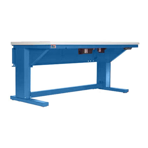
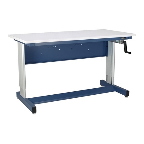
960 Motorized Adjustable Bench
IAC INDUSTRIES
3831 S BULLARD AVE., GOODYEAR, AZ 85338
Phone (714) 990-8997 Fax (714) 990-0557
www.iacindustries.com
960 Motorized ADJ. HI
REV. (042318P65)Assembly Instructions

2
Table Of Contents
Page #
2 Pre-assembly Check List
3 WARNING of instability
4 960 Hand Crank Assembly Drawing 48L only
5 960 Hand Crank Assembly Drawing 60L and Up
6-7 960 Hand Crank Adjustable Bench Instructions
8-9 ESD Grounding
9 Cleaning
ATTENTION NOTES:
IAC Industries takes great care in the packing of its products, however damage can occur
during shipment. Check all packages and parts for any signs of damage. If damage is evident
STOP and contact the carrier that delivered your order. Request a freight claim inspector to
document the damage and begin the freight claim process.
Tools required to assemble your products are:
7/16” and 1/2” wrench or socket with ratchet. Phillips screwdriver 8” long.
Utility knife. Safety glasses and light duty protective gloves.
Power tools are NOT recommended unless they are equipped with a torque-limiting device
which can limit the torque to 10-foot lbs maximum.
Unpack your order and separate like parts. Be careful not to damage parts as they are being
moved into position. Also be sure all parts are removed from the packing materials before
these materials are thrown away.
Locate the hardware kits and keep them in a central area. If the assembly is going to take
more than one day, all individual hardware pieces should be returned to a central location.
Attention Notes (cont)
Check all parts and hardware kits against the itemized packing list found with the assembly
instructions. If you believe there are parts missing from your order please contact IAC
Industries customer service at 800-989-1422.
WARNING:
ALL PARTICLE BOARD USED IN IAC INDUSTRIES PRODUCTS ARE SOURCED ONLY FROM VENDORS THAT ARE CARB
ATCM PHASE 2 AND TSCA TITLE VI COMPLIANT WITH VALID CERTIFICATES.Drilling, Sawing, Sanding or Machining Wood products
can expose you to wood dust, a substance known to the state of California to cause cancer. Avoid inhaling dust generated from wood products or use a
dust mask to other safeguards for personal protection. This product can expose you to chemicals, including formaldehyde, which is known to the state
of California to cause cancer, and methanol, which is known to the state of California to cause birth defects or other reproductive harm. For more
information please visit, www.P65WARNINGS.CA.GOV/WOOD. COPY OF VENDOR CERTIFICATE AVAILABLE UPON REQUEST.

3
Step 1: With Accessories installed, Press the Remote “UP” button and between mid-point to highest
point, check to see if the top moves back and forth when the work surface is pushed (there will be some
play, but it should be minimum)
Step 2: If top is stable, your top will not need any adjustments made.
If you find that the top is unstable at the higher levels, lower the bench (Remote “Down” button and
using an Allen wrench to turn the top setscrew clockwise 1/4 to 1/2 a turn only.
Please Note:
Make sure to check both pedestal legs when making adjustments. One may need more or less turns
then the other pedestal leg.
Step 3: After adjusting both Pedestal legs repeat “Step 1” and check for both stability and that the
top moves down as the Remote button is pushed down. If the top has trouble moving down, readjust
the Top set screws CCW a 1/4 of a turn at a time until the bench rises and lowers evenly.

4
960 Bench Assembly Drawing 48 Long (Figure 1)

5
960 Bench Assembly Drawing (Figure 2)

6
Parts List: 960 Motorized Adjustable Bench (Ref. Figure 1&2)
Item Description Qty. Item Description Qty.
1 Work surface (STD. or ESD) 1 E Screw, 10-32x1.00” PPH 2
2 960 Leg Sub-Assy-RT & LT ea 1 F Screw, #6x .50 PPH/SMS 4
3 Front Support Beam 1.5"H 1 G Tie Mount, Plastic 4
4 Std. Support Beam 3”H 1 H Cable Tie 4
5 950/960 Modesty Panel 1 I
A Hex Head Bolt 1/4-20x.75 20 J Nut, Well Nut 10-32 Neoprene 2
B Flat Washer 1/4” 20 K Brkt, Motorized Hgt. Adj.Switch MTG 1
C Hex Head Bolt 5/16-18x.75 8
D Flat Washer 5/16 8
Hardware Kit: HWR 465
1/4-20x.75 1/4-20 5/16-18x.75 5/16-18 10-32x 1.00L Well Nut 10-32
HH Bolt Flat Washer HH Bolt Flat Washer PPH Screw
CAUTION: Do not operate Motorized /cylinders without the weight of the worksurface on the
frame. To do so may cause a vacuum in the lines and possible damage.
Be cautious to hold the leg assemblies together when turning workbench over after
assembly making sure they do not separate.
1. Place Bench Top (Item 1) on clean surface with underside facing up.
2. Loosely attach front and rear support beams (items 3 & 4) to leg assemblies (item 2) using
5/16-18 x .75 hex head bolts (item D) and 5/16 flat washers (item E).
3. Loosely attach modesty panel (item 5) to leg assemblies (item 2) using 1/4-20 x .75 hex head
bolts (item B) and1/4 flat washers (item C).
4. Secure motorized pump system to the worksurface of 60” and longer benches using six (6)
1/4-20 x .75 hex head bolts (item A) and six (6) 1/4 flat washers (item B) as shown in Figure 2.
For 48” benches secure motorized pump to the modesty panel using six (6) 1/4-20 x .75 hex
head bolts (item A) and six (6) 1/4 flat washers (item B) as shown in Figure 1. Align mounting
slots in bench frame assembly with inserts in worksurface and attach using 1/4-20 x .75 hex
head bolts (item A) and1/4 flat washers (item B). Square the frame and tighten the front and
rear beams first. Then tighten the worksurface bolts being careful not to over tighten.

7
Assembly Instructions (Continued) ……………
5. Attach motorized pump system’s switch to front support beam (item 3) as shown below using
10-32x 1.00” pan phillips head screw (item E) with well nut 10-32 (item J) and 5/16 flat washer
(item D) two places.
6. While the bench is upside-down plug the motor system into a power source and raise the leg
assemblies to their highest point. Secure motorized pump hydraulic lines to underside of the
worksurface using cable mounts (items G) cable ties (items H) and #6x1/2 phillips screws
(items F) being sure not to kink or damage the lines in anyway.
7. Lower the leg assemblies SLOWLEY using the switch. If the leg assemblies do not lower
apply pressure to them by pushing down on each leg. Once the leg assemblies are at their
lowest level check to make sure the hydraulic lines are not kinked or pinched by the frame in
anyway.
8. When turning bench assembly right side up be sure the leg assemblies DO NOT separate as
this may cause damage to the hydraulic system. It may take as many as 4 people to turn
bench over.
9. When moving the bench into place, make sure to lift it by the bottom of the leg assemblies
only. DO NOT lift bench by the worksurface as this will cause damage to the hydraulic system.
(See Caution Note Above) Level bench using floor glides at bottom of leg assemblies.

8
ESD GROUNDING:
HWR-014 ESD Hardware Kit
ESD refers to the OPTIONAL static dissipative laminate used on the bench. The laminate has a
conductive under layer that comes in contact with the factory installed grounding bolts in the
worksurface. The ESD grounding kit, including the 10 ft. grounding wire must be attached and the
bench must be properly grounded to your facility earth ground. (See below for grounding cautions!)
The eyelet slips over the bolt end and the alligator clip attaches to ground. When tested with a
megohmmeter the ground bolts should test at 1 (1x10⁶) to 1000 (1x10⁹) in accordance with EOS/ESD
standards prescribed in EOS/ESD document S4.1-1990 Worksurfaces-Resistive Characterization. For
specific details on grounding the bench consult EOS/ESD document S6.1-1991 Grounding -
Recommended Practice.

9
GROUNDING CAUTIONS:
1.) Ground each bench individually to ground, NEVER to each other in a continuous daisy chain.
2.) ISOLATED ground receptacles should not be used to derive an ESD ground.
3.) The green wire in a standard wall duplex can be used as a ground if it has been absolutely
determined that the green wire is attached to earth ground in your facility, thereby providing a real
earth ground.
4.) Each component of an ESD station should be connected to the same common ground point. In
other words, use only ONE of the ground bolts as a path to ground. There are 2 installed for
convenience only, or in the event you purchase a continuous resistance monitor.
5.) DON’T use power tools to install the nuts for the grounding kit. HAND TIGHTEN ONLY. If you
attempt to 'spin' the ground bolt, the serrated teeth under the head of the bolt might strip the thin
conductive layer.
NOTE: If benches are moved to another location, the ground bolts in the worksurfaces should be re-
tested. Refer to EOS/ESD document S4.1-1990 Worksurfaces-Resistive Characterization for proper
testing methods. If ground has been disturbed between the bolt and the static dissipative laminate, DO
NOT OVER TIGHTEN ground bolts to achieve proper ground. If ground cannot be re-established,
loosen nuts underneath bolt and remove ground bolt from hole. It may be necessary to hold the threads
of the bolt with a small screwdriver in order to stabilize it to remove the nuts.
Paint a thin layer of CONDUCTIVE ADHESIVE or CONDUCTIVE PAINT on the small "ledge" of
conductive laminate where the bolt head rests and underneath THE HEAD of the ground bolt. Set bolt
back into the hole while liquid is still wet and test ground immediately. At the point ground is
reestablished, let the liquid dry before reattaching the ground wire.
CLEANING:
Hard surface laminate is designed to resist abrasion, scuffing, scorching, hot solder, flux and most
solvents. Intense exposure, such as from a hot soldering iron is not recommended. The surface cleans
easily with a damp cloth and soapy water. A mild chemical cleaner with no abrasive can be used for
stubborn spots. Remove glue and grease with a non flammable adhesive solvent such as 3M Scotch-
Grip Solvent No. 4-F. Stains can be removed with a two minute exposure to a 5% hypo chloride bleach
solution, followed by a clean water rinse. Never wax surface, as waxes may insulate.
Table of contents
Other IAC INDUSTRIES Tools Storage manuals