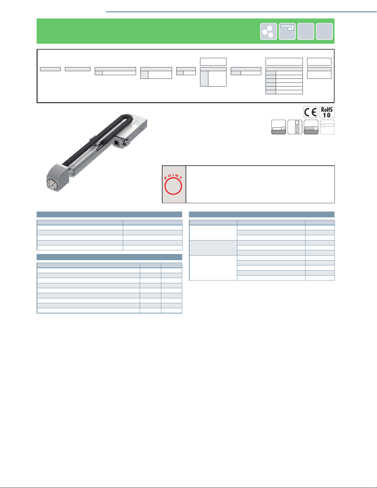
IAI ROBO Cylinder RCP6-RRA User manual

ROBO Cylinder® Pulse Press RCP6-RRA
Catalog No. CE0286-2A (2021OCT)
www.intelligentactuator.com
IAI Industrieroboter GmbH
Ober der Röth 4, D-65824 Schwalbach am Taunus, Germany
IAI (Shanghai) Co., Ltd.
Shanghai Jiahua Business Center A8-303, 808,
Hongqiao Rd., Shanghai 200030, China
IAI Robot (Thailand) Co., Ltd.
825 Phairojkijja Tower 7th Floor, Debaratana Rd.,
Bangna Nuea, Bangna, Bangkok 10260, Thailand
The information contained in this product brochure may change without prior notice due to product improvements.
USA Headquarters & Western Region (Los Angeles) : 2690 W. 237th Street, Torrance, CA 90505 (310) 891-6015
Midwest Branch Office (Chicago) :110 East State Parkway, Schaumburg, Illinois 60173 (847) 908-1400
Southeast Branch Office (Atlanta) : 1220 Kennestone Circle, Suite 108, Marietta, GA 30066 (678) 354-9470
IAI America, Inc.
JAPAN Headquarters : 577-1 Obane, Shimizu-ku, Shizuoka-shi, Shizuoka, 424-0103, JAPAN
www.intelligentactuator.com

Actuator compatible with
presses that allows for simple power control
Capable of both pushing and pulling
1
Lineup
3
Reasonable cost
2
Select from several types based on use (push force from 60N to 2,000N).
A pulse press is an actuator combining a
stepper motor and load cell, that is
capable of performing power control.
It provides a loading repeatability of
±1.0% F.S. (full scale), based on feedback
from the load cell.
Equipped with a stepper motor, it is less than half the cost of an IAI servo press.
Both pushing and pulling are supported in the load direction. There are
no limitations on pushing or pulling times.
RCP6-RRA4R
RCP6-RRA6R
RCP6-RRA7R
60N~300N
60N~600N
200N~2,000N
Example) Washer press tting (pushing)
Example) Wire harness pulling test
What is a pulse press?
IAI's new
pulse press!
POINT
F.S. : Full Scale
Maximum measurable value
System for inspecting
air leaks in sweet bread
packaging
Example
Load cell
RCP6-RRA
(pulse press)
PCON-CBP
(pulse press dedicated
controller)
Stepper motor
Feedback
(load information)
1

Actuator compatible with
presses that allows for simple power control
Capable of both pushing and pulling
1
Lineup
3
Reasonable cost
2
Select from several types based on use (push force from 60N to 2,000N).
A pulse press is an actuator combining a
stepper motor and load cell, that is
capable of performing power control.
It provides a loading repeatability of
±1.0% F.S. (full scale), based on feedback
from the load cell.
Equipped with a stepper motor, it is less than half the cost of an IAI servo press.
Both pushing and pulling are supported in the load direction. There are
no limitations on pushing or pulling times.
RCP6-RRA4R
RCP6-RRA6R
RCP6-RRA7R
60N~300N
60N~600N
200N~2,000N
Example) Washer press tting (pushing)
Example) Wire harness pulling test
What is a pulse press?
IAI's new
pulse press!
POINT
F.S. : Full Scale
Maximum measurable value
System for inspecting
air leaks in sweet bread
packaging
Example
Load cell
RCP6-RRA
(pulse press)
PCON-CBP
(pulse press dedicated
controller)
Stepper motor
Feedback
(load information)
2

Easy setup using a dedicated tool
Pushing/pulling can easily be setup using the PC teaching
software or teaching pendant.
PC teaching software (screenshot)
Example of washer press fitting
Position No. 1
start signal
input
Completion
signal output
Moves to position
No. 2 immediately
before workpiece
Begins push-motion
operation at a push
speed of 10mm/s
Arrives at
specified push
force*
Position
of 0mm
Position
of 50mm
Push force of
302N reached
Approach Push Complete
* A completion signal is
not output if the specified
push force is not reached
until the push width value.
3

Easy setup using a dedicated tool
Pushing/pulling can easily be setup using the PC teaching
software or teaching pendant.
PC teaching software (screenshot)
Example of washer press fitting
Position No. 1
start signal
input
Completion
signal output
Moves to position
No. 2 immediately
before workpiece
Begins push-motion
operation at a push
speed of 10mm/s
Arrives at
specified push
force*
Position
of 0mm
Position
of 50mm
Push force of
302N reached
Approach Push Complete
* A completion signal is
not output if the specified
push force is not reached
until the push width value.
Model Specification Items
Specification Table
P3 ( )
RCP6 WA
Series Type Encoder Motor type Lead Stroke
Applicable
controllers
Cable
length Options
RRA4R Side-mounted
rod 40mm width
RRA6R Side-mounted
rod 58mm width
RRA7R Side-mounted
rod 73mm width
35P (RRA4R type) 35stepper motor
42P (RRA6R type) 42stepper motor
56P (RRA7R type) 56stepper motor
(RRA4R type) (RRA6R type) (RRA7R type)
110
~
310
110mm
~
310mm
115
~
315
115mm
~
315mm
120
~
320
120mm
~
320mm
(every 50mm)
2.5 (RRA4R type)
Lead 2.5mm
1.5 (RRA6R type)
Lead 1.5mm
4(RRA7R type)
Lead 4mm
2(RRA7R type)
Lead 2mm
WA Battery-less
absolute
P3 PCON-CBP/CGBP
*The range of selections varies according to the actuator type.
Please refer to the pages of each type for details.
NNo
P1m
S3m
M5m
X Specified length
R Robot cable
BBrake
CJB Cable exit direction (bottom)
CJO Cable exit direction (outside)
CJT Cable exit direction (top)
FL Flange (front)
FT Foot bracket
LCT Equipped with load cell
(standard equipment)
ML Motor side-mounted (left)
MR Motor side-mounted (right)
Type
Stroke (mm) and max speed (mm/s)
Lead
(mm)
Max. push/
pull force
(N)
Payload
(kg) Reference
page
Horizontal Vertical
110 115 120 - Stroke can be selected in 50mm units - 310 315 320
RRA4R 2.5 300 3 3 P5
RRA6R 1.5 600 10 10 P9
RRA7R
4 1,000 10 10
P13
2 2,000 10 10
200
* Length of band = Stroke (*Numbers in band = Maximum speed by stroke)
110
160
85
4

RCP6 ROBO Cylinder®
24V
Stepper
Motor
Body Width
40
mm
Side-mounted
Motor
Battery-
less
Absolute
RCP6-RRA4R (Pulse press specification)
■Model Specification Items
RCP6 -RRA4R -WA -35P -2.5 - - P3 - -
Series - Type - Encoder type - Motor type - Lead - Stroke - Applicable controllers - Cable length - Option
WA Battery-less absolute 35P Stepper motor 2.5 2.5mm 110 110mm P3 PCON NNo Refer to Options
below.
35size
~
~
P1m
310 310mm S3m
(every 50mm) M5m
X Specied length
R Robot cable
(Note) The figure above is the motor side-mounted to left (ML).
Horizontal
Vertical
Side
Ceiling
■Stroke
Stroke (mm) RCP6-RRA4R
110
160
210
260
310
■Options * Please check the Options reference pages to confirm each option.
Name
Option code
Reference page
Brake (Note 1) B17
Cable exit direction (bottom) (Note 1, 2) CJB 17
Cable exit direction (outside) (Note 1) CJO 17
Cable exit direction (top) (Note 1) CJT 17
Flange (front) (Note 1) FL 17
Foot bracket (Note 2, 3) FT 18
Equipped with load cell (standard equipment) (Note 4) LCT 18
Motor side-mounted (left) (Note 5) ML 18
Motor side-mounted (right) (Note 5) MR 18
(Note 1) Cable exit direction (CJB/CJO/CJT) and flange (front) (FL) cannot be selected
when selecting brake (B) with a stroke of 110mm.
(Note 2) Foot bracket (FT) cannot be selected when selecting cable exit direction (bottom)
(CJB).
(Note 3) Please refer to P. 18 for the number of brackets included.
(Note 4) Be sure to enter a selection in the options section of the model number.
(Note 5) Be sure to enter a code in the options section of the model number.
■Cable Length
Type Cable code P3
Standard type
P(1m)
S(3m)
M(5m)
Specified length
X06(6m) ~ X10(10m)
X11(11m) ~ X15(15m)
X16(16m) ~ X20(20m)
Robot cable
R01(1m) ~ R03(3m)
R04(4m) ~ R05(5m)
R06(6m) ~ R10(10m)
R11(11m) ~ R15(15m)
R16(16m) ~ R20(20m)
Selection
Notes
(1) There are no limitations on the continuous push time or continuous pull time.
(2) Continuous operation is possible at a duty ratio of 100%.
(3) Pay close attention to the mounting method of the body. Please refer to P. 20 for
details.
(4) Pay close attention to the mounting orientation. Please refer to P. 20 for details.
(5) Please refer to P. 20 for information on load cells.
RCP6-RRA4R
5

RCP6 ROBO Cylinder®
Item Description
Lead Ball screw lead (mm) 2.5
Horizontal
Payload
Maximum payload (kg)
(high-output enabled) 3
Maximum payload (kg)
(high-output disabled) 3
Speed /
acceleration/
deceleration
Max. speed (mm/s) 200
Rated acceleration/deceleration (G)
0.5
Max. acceleration/deceleration (G)
0.5
Vertical
Payload
Maximum payload (kg)
(high-output enabled) 3
Maximum payload (kg)
(high-output disabled) 3
Speed /
acceleration/
deceleration
Max. speed (mm/s) 200
Rated acceleration/deceleration (G)
0.5
Max. acceleration/deceleration (G)
0.5
Push
Max. push force (N) 300
Min. push force (N) 60
Max. push speed (mm/s) 10
Pull
Max. pull force (N) 300
Min. pull force (N) 60
Max. pull speed (mm/s) 10
Brake Brake specification Non-excitation actuating
solenoid brake
Brake holding force (kg) 3
Stroke
Min. stroke (mm) 110
Max. stroke (mm) 310
Stroke pitch (mm) 50
■Main Specifications
Item Description
Drive system Ball screw, φ8mm, rolled C10
Positioning repeatability ±0.02mm
Lost motion 0.1mm or less
Load cell rated capacity 600N
Loading repeatability (Note 6) ±1.0% F.S. (Note 7)
Ambient operating
temperature, humidity 0 ~ 40°C, 85%RH or less (no condensation)
Ingress protection IP20
Vibration & shock resistance 4.9m/s2
Overseas standards CE marking, RoHS directive
Motor type Stepper motor
Encoder type Battery-less absolute
Number of encoder pulses 8192 pulse/rev
(Note 6) Ratio (in percentage) of the load variations caused by the repeated operations to
the load cell rated capacity.
(Note 7) F.S.: Full Scale, the maximum measurable value.
■Tables of Payload by Speed/Acceleration
■High-output setting enabled (the unit for payload is kg)
Orientation Horizontal Vertical
Speed
(mm/s)
Acceleration (G)
0.5 0.5
0 3 3
40 3 3
85 3 3
130 3 3
150 3 3
200 3 3
■High-output setting disabled (the unit for payload is kg)
Orientation Horizontal Vertical
Speed
(mm/s)
Acceleration (G)
0.5 0.5
0 3 3
40 3 3
85 3 3
130 3 3
150 3 3
■Stroke and Max Speed
High-output
setting
Stroke (mm)
110 160 210 260 310
Enabled 200
Disabled 150
(Unit: mm/s)
Push force (N)
0
50
100
150
200
250
300
350
0 20 40 60 80 100
Push command value (%)
■C
orrelation diagram between push force and push command value
Pull force (N)
0
50
100
150
200
250
300
350
0 20 40 60 80 100
Pull command value (%)
■C
orrelation diagram between pull force and pull command value
RCP6-RRA4R 6

RCP6 ROBO Cylinder®
*1 The 2 counterbored mounting holes shown in the figure cannot be used.
(Note) When returning to the home position, the rod will move to the M.E. Be careful of interference with surrounding objects.
ST: Stroke
M.E: Mechanical end
S.E: Stroke end
S
S
V
V
Load cell tip mounting jig reference size
4 4
ST
30
A
L
98.5
31.5
1.5
φ24h7
φ20 (rod outer diameter)
S.E.M.E. Home M.E.
3210
32
40
6
4-M4 depth 9 (20)
(26)
39
40
97
(6) 40
48
(8.7)
52
71
103
26
19.5
(11)
53
Base mounting surface
Reference surface
(Dimension B range)
20
C
B 16
17
K (between φ3 hole - φ3 hole)
J (φ3 hole - oblong hole)
2-φ3H7 reamed, depth 4
(from base mounting surface)
E-M4 depth 6
14
H-φ3.4 through,
6.5 deep counterbored,
depth 3.5 (from the opposite side)
G×100P
1250
50 F
D×100P
Oblong hole
*1 Unavailable
P
40°
40°
P.C.D.30
4-M4 depth 8
Cross section of S-S
45°
45°
φ5H7 reamed, depth 5
φ10H7 depth 5
P.C.D.30.5
4-M5 depth 8
Jig mounting dimensions details
(equidistant)
4
Depth 4 from base seating surface
(R)
Detailed view of P
Base oblong hole details
(43.3)
Cable connection
(16.2)
(15.6)
Cable exit direction (option)
22
135 (w/o brake)
179 (with brake)
P.C.D.30.5
φ42 or more
45°
45°
4-φ5.5 through,
φ9.5 deep counterbored,
depth 5.5
(equidistant)
4
φ10h7
R0.5 or less
φ5H7 reamed
3+0.010
0
Must be
100 or more
2
φ42 (load cell outer diameter)
136 (w/o brake)
180 (with brake) 27
67
26
Cable exit direction (option)
CJB
bottom
CJO
outside
CJT
top
0.5
1
2.5 3.5
φ3.4
φ6.5
Cross section V-V
Details of base mounting counterbored holes
■Dimensions by stroke
Stroke 110 160 210 260 310
L 244 294 344 394 444
A 214 264 314 364 414
B 184 234 284 334 384
C 50 100 50 100 50
D 1 1 2 2 3
E 6 6 8 8 10
F 100 50 100 50 100
G 0 1 1 2 2
H 8 10 10 12 12
J 85 85 185 185 285
K 100 100 200 200 300
■Mass by stroke
Stroke 110 160 210 260 310
Mass
(kg)
Without brake 2.2 2.3 2.4 2.6 2.7
With brake 2.4 2.5 2.7 2.8 2.9
■Dimensions
CAD drawings can be downloaded from our website.
www.intelligentactuator.com
3D
CAD
3D
CAD
2D
CAD
2D
CAD
■Applicable Controllers
The actuators on this page can be operated by the controllers indicated below. Please select the type depending on your intended use.
Name External
view
Maximum
number of
connectable
axes
Power
supply
voltage
Control method
Maximum number
of positioning points
Reference
page
Positioner
Pulse-train
Program
Network (*selection)
DV CC CIE PR CN
ML
ML3
EC EP
PRT
SSN
ECM
PCON-CBP/
CGBP 1 24VDC
*Selection - - - - -
512
(768 for network
spec.)
21
(Note) Please refer to P. 8-17 of the General Catalog 2021 for information on network abbreviation codes such as DV and CC.
RCP6-RRA4R
7

RCP6 ROBO Cylinder®
RCP6-RRA4R 8

RCP6 ROBO Cylinder®
24V
Stepper
Motor
Body Width
60
mm
Side-mounted
Motor
Battery-
less
Absolute
RCP6-RRA6R (Pulse press specification)
■Model Specification Items
RCP6 -RRA6R -WA -42P -1.5 - - P3 - -
Series - Type - Encoder type - Motor type - Lead - Stroke - Applicable controllers - Cable length - Option
WA Battery-less absolute 42P Stepper motor 1.5 1.5mm 115 115mm P3 PCON NNo Refer to Options
below.
42size
~
~
P1m
315 315mm S3m
(every 50mm) M5m
X Specied length
R Robot cable
(Note) The figure above is the motor side-mounted to left (ML).
Horizontal
Vertical
Side
Ceiling
■Stroke
Stroke (mm) RCP6-RRA6R
115
165
215
265
315
■Options * Please check the Options reference pages to confirm each option.
Name
Option code
Reference page
Brake B17
Cable exit direction (bottom) (Note 1) CJB 17
Cable exit direction (outside) CJO 17
Cable exit direction (top) CJT 17
Flange (front) FL 17
Foot bracket (Note 1, 2) FT 18
Equipped with load cell (standard equipment) (Note 3) LCT 18
Motor side-mounted (left) (Note 4) ML 18
Motor side-mounted (right) (Note 4) MR 18
(Note 1) Foot bracket (FT) cannot be selected when selecting cable exit direction (bottom)
(CJB).
(Note 2) Please refer to P. 18 for the number of brackets included.
(Note 3) Be sure to enter a selection in the options section of the model number.
(Note 4) Be sure to enter a code in the options section of the model number.
■Cable Length
Type Cable code P3
Standard type
P(1m)
S(3m)
M(5m)
Specified length
X06(6m) ~ X10(10m)
X11(11m) ~ X15(15m)
X16(16m) ~ X20(20m)
Robot cable
R01(1m) ~ R03(3m)
R04(4m) ~ R05(5m)
R06(6m) ~ R10(10m)
R11(11m) ~ R15(15m)
R16(16m) ~ R20(20m)
Selection
Notes
(1) There are no limitations on the continuous push time or continuous pull time.
(2) Continuous operation is possible at a duty ratio of 100%.
(3) Pay close attention to the mounting method of the body. Please refer to P. 20 for
details.
(4) Pay close attention to the mounting orientation. Please refer to P. 20 for details.
(5) Please refer to P. 20 for information on load cells.
RCP6-RRA6R
9

RCP6 ROBO Cylinder®
Item Description
Lead Ball screw lead (mm) 1.5
Horizontal
Payload
Maximum payload (kg)
(high-output enabled) 10
Maximum payload (kg)
(high-output disabled) 10
Speed /
acceleration/
deceleration
Max. speed (mm/s) 110
Rated acceleration/deceleration (G)
0.3
Max. acceleration/deceleration (G)
0.3
Vertical
Payload
Maximum payload (kg)
(high-output enabled) 10
Maximum payload (kg)
(high-output disabled) 10
Speed /
acceleration/
deceleration
Max. speed (mm/s) 110
Rated acceleration/deceleration (G)
0.3
Max. acceleration/deceleration (G)
0.3
Push
Max. push force (N) 600
Min. push force (N) 60
Max. push speed (mm/s) 10
Pull
Max. pull force (N) 600
Min. pull force (N) 60
Max. pull speed (mm/s) 10
Brake Brake specification Non-excitation actuating
solenoid brake
Brake holding force (kg) 10
Stroke
Min. stroke (mm) 115
Max. stroke (mm) 315
Stroke pitch (mm) 50
■Main Specifications
Item Description
Drive system Ball screw, φ10mm, rolled C10
Positioning repeatability ±0.02mm
Lost motion 0.1mm or less
Load cell rated capacity 600N
Loading repeatability (Note 6) ±1.0% F.S. (Note 7)
Ambient operating
temperature, humidity 0 ~ 40°C, 85%RH or less (no condensation)
Ingress protection IP20
Vibration & shock resistance 4.9m/s2
Overseas standards CE marking, RoHS directive
Motor type Stepper motor
Encoder type Battery-less absolute
Number of encoder pulses 8192 pulse/rev
(Note 6) Ratio (in percentage) of the load variations caused by the repeated operations to
the load cell rated capacity.
(Note 7) F.S.: Full Scale, the maximum measurable value.
■High-output setting enabled (the unit for payload is kg)
■Tables of Payload by Speed/Acceleration
Orientation Horizontal Vertical
Speed
(mm/s)
Acceleration (G)
0.3 0.3
0 10 10
35 10 10
70 10 10
100 10 10
110 10 10
■High-output setting disabled (the unit for payload is kg)
Orientation Horizontal Vertical
Speed
(mm/s)
Acceleration (G)
0.3 0.3
0 10 10
35 10 10
80 10 10
■Stroke and Max Speed
High-output
setting
Stroke (mm)
115 165 215 265 315
Enabled 110
Disabled 80
(Unit: mm/s)
Push force (N)
0 20 40 60 80 100
Push command value (%)
0
100
200
300
400
500
600
700
■C
orrelation diagram between push force and push command value
Pull force (N)
0 20 40 60 80 100
Pull command value (%)
0
100
200
300
400
500
600
700
■C
orrelation diagram between pull force and pull command value
RCP6-RRA6R 10

RCP6 ROBO Cylinder®
ST: Stroke
M.E: Mechanical end
S.E: Stroke end
(Note) When returning to the home position, the rod will move to the M.E. Be careful of interference with surrounding objects.
S
S
W
W
3 3
ST
36
A
L
98.5
31.5
2
φ25 (rod O.D.)
φ30h7
M.E.
Home
S.E.
M.E.
67
67
4-M6 depth 14 (40)
(40)
149
73
70(1)
136
(11)
58
57
7
(5.1)
28.5
52
33
85
60
16
Base mounting surface
Reference surface
(Dimension B range)
18
3-φ4 H7 reamed, depth 5.5
(from base mounting surface)
E-M5 depth 10
K (φ4 hole - φ4 hole)
D×100P 65 10
15
B
28
H-φ4.5 through,
φ8 deep counterbored, depth 4.5
(from the opposite side)
30G×100P
J
(φ4 hole - oblong hole)
Oblong hole P
45°
45°
P.C.D.40
4-M6 depth 12
Cross section of S-S
(equidistant)
Depth 5.5
from base mounting surface
(R)
5
Detailed view of P
Base oblong hole details
45°
45°
φ5H7 reamed, depth 5
φ10H7 depth 5
P.C.D.30.5
4-M5 depth 8
Jig mounting dimensions details
(equidistant)
φ3.5
port diameter
32.5
Grease tting
for ball screw/guide
(same on opposite side)
Arrow view V
Greasing port
(43.3)
Cable connection
(16.2)
(15.6)
117 (w/o brake)
157 (with brake)22
φ42 or more
P.C.D.30.5
45°
45°
4-φ5.5 through,
φ9.5 deep counterbored,
depth 5.5
Load cell tip mounting jig reference size
(equidistant) 4
R0.5 or less
φ10h7
φ5H7 reamed
4+0.012
0
(36)
Must be 100 or more
2
38.5
φ42 (load cell outer diameter)
67
125 (w/o brake)
165 (with brake)
V
28.5
CJO
outside
Cable exit direction (option)
CJB
bottom
CJT
top
φ8
φ4.5
5
0.5
5.5 4.5
Cross section of W-W
Details of base mounting counterbored holes
■Dimensions by stroke
Stroke 115 165 215 265 315
L 291 341 391 441 491
A 255 305 355 405 455
B 222 272 322 372 422
D 1 1 2 2 3
E 6 6 8 8 10
G 1 2 2 3 3
H 4 6 6 8 8
J 85 85 185 185 285
K 100 100 200 200 300
■Mass by stroke
Stroke 115 165 215 265 315
Mass
(kg)
Without brake 4.0 4.2 4.5 4.7 4.9
With brake 4.2 4.4 4.6 4.9 5.1
■Dimensions
CAD drawings can be downloaded from our website.
www.intelligentactuator.com
3D
CAD
3D
CAD
2D
CAD
2D
CAD
■Applicable Controllers
The actuators on this page can be operated by the controllers indicated below. Please select the type depending on your intended use.
Name External
view
Maximum
number of
connectable
axes
Power
supply
voltage
Control method
Maximum number
of positioning points
Reference
page
Positioner
Pulse-train
Program
Network (*selection)
DV CC CIE PR CN
ML
ML3
EC EP
PRT
SSN
ECM
PCON-CBP/
CGBP 1 24VDC
*Selection - - - - -
512
(768 for network
spec.)
21
(Note) Please refer to P. 8-17 of the General Catalog 2021 for information on network abbreviation codes such as DV and CC.
RCP6-RRA6R
11

RCP6 ROBO Cylinder®
RCP6-RRA6R 12

RCP6 ROBO Cylinder®
24V
Stepper
Motor
Body Width
70
mm
Side-mounted
Motor
Battery-
less
Absolute
RCP6-RRA7R (Pulse press specification)
■Model Specification Items
RCP6 -RRA7R -WA -56P - - - P3 - -
Series - Type - Encoder type - Motor type - Lead - Stroke - Applicable controllers - Cable length - Option
WA Battery-less absolute 56P Stepper motor 44mm 120 120mm P3 PCON NNo Refer to Options
below.
56size 22mm
~
~
P1m
320 320mm S3m
(every 50mm) M5m
X Specied length
R Robot cable
(Note) The figure above is the motor side-mounted to left (ML).
Horizontal
Vertical
Side
Ceiling
■Stroke
Stroke (mm)
RCP6-RRA7R
Lead 4
(1000N)
Lead 2
(2000N)
120
170
220
270
320
■Options * Please check the Options reference pages to confirm each option.
Name
Option code
Reference page
Brake B17
Cable exit direction (bottom) (Note 1) CJB 17
Cable exit direction (outside) CJO 17
Cable exit direction (top) CJT 17
Flange (front) FL 17
Foot bracket (Note 1, 2) FT 18
Equipped with load cell (standard equipment) (Note 3) LCT 18
Motor side-mounted (left) (Note 4) ML 18
Motor side-mounted (right) (Note 4) MR 18
(Note 1) Foot bracket (FT) cannot be selected when selecting cable exit direction (bottom)
(CJB).
(Note 2) Please refer to P. 18 for the number of brackets included.
(Note 3) Be sure to enter a selection in the options section of the model number.
(Note 4) Be sure to enter a code in the options section of the model number.
■Cable Length
Type Cable code P3
Standard type
P(1m)
S(3m)
M(5m)
Specified length
X06(6m) ~ X10(10m)
X11(11m) ~ X15(15m)
X16(16m) ~ X20(20m)
Robot cable
R01(1m) ~ R03(3m)
R04(4m) ~ R05(5m)
R06(6m) ~ R10(10m)
R11(11m) ~ R15(15m)
R16(16m) ~ R20(20m)
Selection
Notes
(1) There are no limitations on the continuous push time or continuous pull time.
(2) Continuous operation is possible at a duty ratio of 100%.
(3) Pay close attention to the mounting method of the body. Please refer to P. 20 for
details.
(4) Pay close attention to the mounting orientation. Please refer to P. 20 for details.
(5) Please refer to P. 20 for information on load cells.
RCP6-RRA7R
13

RCP6 ROBO Cylinder®
Item Description
Lead Ball screw lead (mm) 4 2
Horizontal
Payload
Maximum payload (kg)
(high-output enabled) 10 10
Maximum payload (kg)
(high-output disabled) 10 10
Speed /
acceleration/
deceleration
Max. speed (mm/s) 160 85
Rated acceleration/deceleration (G)
0.3 0.3
Max. acceleration/deceleration (G)
0.3 0.3
Vertical
Payload
Maximum payload (kg)
(high-output enabled) 10 10
Maximum payload (kg)
(high-output disabled) 10 10
Speed /
acceleration/
deceleration
Max. speed (mm/s) 160 85
Rated acceleration/deceleration (G)
0.3 0.3
Max. acceleration/deceleration (G)
0.3 0.3
Push
Max. push force (N) 1000 2000
Min. push force (N) 200 200
Max. push speed (mm/s) 10 10
Pull
Max. pull force (N) 1000 2000
Min. pull force (N) 200 200
Max. pull speed (mm/s) 10 10
Brake Brake specification Non-excitation actuating
solenoid brake
Brake holding force (kg) 10 10
Stroke
Min. stroke (mm) 120 120
Max. stroke (mm) 320 320
Stroke pitch (mm) 50 50
■Main Specifications
Item Description
Drive system Ball screw, φ12mm, rolled C10
Positioning repeatability ±0.02mm
Lost motion 0.1mm or less
Load cell rated capacity 2000N
Loading repeatability (Note 6) ±1.0% F.S. (Note 7)
Ambient operating
temperature, humidity 0 ~ 40°C, 85%RH or less (no condensation)
Ingress protection IP20
Vibration & shock resistance 4.9m/s2
Overseas standards CE marking, RoHS directive
Motor type Stepper motor
Encoder type Battery-less absolute
Number of encoder pulses 8192 pulse/rev
(Note 6) Ratio (in percentage) of the load variations caused by the repeated operations to
the load cell rated capacity.
(Note 7) F.S.: Full Scale, the maximum measurable value.
■High-output setting enabled (the unit for payload is kg)
■Tables of Payload by Speed/Acceleration
Orientation Horizontal Vertical
Speed
(mm/s)
Acceleration (G)
0.3 0.3
0 10 10
35 10 10
70 10 10
115 10 10
160 10 10
Lead 4 (1000N)
Orientation Horizontal Vertical
Speed
(mm/s)
Acceleration (G)
0.3 0.3
0 10 10
35 10 10
70 10 10
85 10 10
Lead 2 (2000N)
■High-output setting disabled (the unit for payload is kg)
Orientation Horizontal Vertical
Speed
(mm/s)
Acceleration (G)
0.3 0.3
0 10 10
35 10 10
70 10 10
115 10 10
Lead 4 (1000N)
Orientation Horizontal Vertical
Speed
(mm/s)
Acceleration (G)
0.3 0.3
0 10 10
35 10 10
60 10 10
Lead 2 (2000N)
■Stroke and Max Speed
Lead
(mm)
Push
force
Pull
force
High-
output
setting
Stroke (mm)
120 170 220 270 320
4
1000N
Enabled
160
Disabled
115
2
2000N
Enabled
85
Disabled
60
(Unit: mm/s)
Push force (N)
0 20 40 60 80 100
Push command value (%)
0
200
400
600
800
1000
1200
1400
1600
1800
2000
2200
Lead 2
Lead 4
■C
orrelation diagram between push force and push command value
Pull force (N)
0 20 40 60 80 100
Pull command value (%)
0
200
400
600
800
1000
1200
1400
1600
1800
2000
2200
Lead 2
Lead 4
■C
orrelation diagram between pull force and pull command value
RCP6-RRA7R 14

RCP6 ROBO Cylinder®
ST: Stroke
M.E: Mechanical end
S.E: Stroke end
(Note) When returning to the home position, the rod will move to the M.E. Be careful of interference with surrounding objects.
S
S
W
W
3 3
ST
38.5A
L
133
39
2
φ30 (rod outer diameter)
φ35h7
M.E.HomeS.E.M.E.
82
82
4-M8 depth 16 (50)
(50)
17
100
168
7373
(6.2)
(1) 70
72
152.2
(13.5)
60
36
33
63
16
Reference surface
(Dimension B range)
Base mounting surface
34
B
28
3060
40
K (φ4 hole - φ4 hole)
E-M5 depth 9
3-φ4H7 reamed, depth 6
(from base mounting surface)
D×100P
(38.5)
H-φ6 through,
φ9.5 deep counterbored,
depth 5.5 (from the opposite side)
45
G×100P
J (φ4 hole - oblong hole)
Oblong hole P
P.C.D.46
45°
45°
4-M8 depth 16
Cross section of S-S
(equidistant)
Depth
6 from base mounting surface
5
(R)
Detailed view of P
Base oblong hole details
45°
45°
φ8H7 reamed, depth 8
4-M8 depth 14
P.C.D.34
φ15H7 depth 5
Jig mounting dimensions details
(equidistant)
φ3.5
port diameter
29
Arrow view V
Greasing port
Grease tting
for ball screw/guide
(same on opposite side)
(43.3)
Cable connection
(16.2)
(15.6)
135 (w/o brake)
185 (with brake)22
φ50 or more
P.C.D.34
45°
45°
4-φ9 through,
φ14 deep counterbored,
depth 8.5
Load cell tip mounting jig reference size
(equidistant) 4
φ15h7
R0.5 or less
φ8H7 reamed
4+0.012
0
5
0.5
φ9.5
φ6
5.5 5.5
Cross section of W-W
Details of base mounting counterbored holes
Must be 100 or more
2
φ50 (load cell outer diameter)
94
143 (w/o brake)
193 (with brake) 38.5
V
28.5
CJO
outside
CJB
bottom
Cable exit direction (option)
CJT
top
■Dimensions by stroke
Stroke 120 170 220 270 320
L 318.5 368.5 418.5 468.5 518.5
A 280 330 380 430 480
B 218 268 318 368 418
D 1 1 2 2 3
E 6 6 8 8 10
G 1 2 2 3 3
H 4 6 6 8 8
J 85 85 185 185 285
K 100 100 200 200 300
■Mass by stroke
Stroke 120 170 220 270 320
Mass
(kg)
Without brake 6.0 6.3 6.6 6.9 7.2
With brake 6.6 6.9 7.2 7.5 7.8
■Dimensions
CAD drawings can be downloaded from our website.
www.intelligentactuator.com
3D
CAD
3D
CAD
2D
CAD
2D
CAD
■Applicable Controllers
The actuators on this page can be operated by the controllers indicated below. Please select the type depending on your intended use.
Name External
view
Maximum
number of
connectable
axes
Power
supply
voltage
Control method
Maximum number
of positioning points
Reference
page
Positioner
Pulse-train
Program
Network (*selection)
DV CC CIE PR CN
ML
ML3
EC EP
PRT
SSN
ECM
PCON-CBP/
CGBP 1 24VDC
*Selection - - - - -
512
(768 for network
spec.)
21
(Note) Please refer to P. 8-17 of the General Catalog 2021 for information on network abbreviation codes such as DV and CC.
RCP6-RRA7R
15

RCP6 ROBO Cylinder®
RCP6-RRA7R 16

Options
Options
Brake
Description
Model
B
When the actuator is mounted vertically, this works as a holding mechanism that prevents the rod from falling and damaging
any attachments when the power or servo is turned off.
Cable exit direction
This option allows the exit direction of the motor-encoder cable to be changed to top, bottom, or outside.
Description
Model
CJT / CJB / CJO
Top: CJT
Side-mounted motor type
Side-mounted motor direction: Left side (ML)
Bottom: CJB
Top: CJT
Side-mounted motor type
Side-mounted motor direction: Right side (MR)
Bottom: CJB
Outside: CJO
Outside: CJO
Flange (front)
This bracket is used for mounting the actuator body side with bolts.
Description
Model
FL
26
Base mounting surface
4-φ4.5 through
75
65
32.5
32
23
10
14.5
φ4H7 reamed, depth 5
Base mounting surface
Oblong hole depth 5
S
(21.5)
10
88.5 (home position)
37.5
(R)
5
Detailed view: S
+0.012
0
4
RCP6-RRA4R(LCT)
Individual model number: RCP6L-FL-RRA4 (Note 1)
(Individual weight: 0.14kg / Material: Steel)
33
Base mounting surface
12
86.5 (home position)
(19.5)
42.5
85
72
3814
20.5 25
36
φ
6H7 reamed, depth 6
Oblong hole depth 6
Base mounting surface
S
(R)
8
Detailed view: S
6
4-φ6.6 through
RCP6-RRA6R(LCT)
Individual model number: RCP6L-FL-RRA6 (Note 1)
(Individual weight: 0.20kg / Material: Steel)
Base mounting surface
33
15118 (home position)
(24)
52.5
4-φ9 through
47
30
9.5
18
105
89
44.5
φ8H7 reamed, depth 8
Base mounting surface
Oblong hole depth 8
S
10
(R)
Detailed view: S
+0.015
0
8
RCP6-RRA7R(LCT)
Individual model number: RCP6L-FL-RRA7 (Note 1)
(Individual weight: 0.36kg / Material: Steel)
(Note 1) 4 hex socket bolts enclosed
17 Options
17

Options
a
Foot bracket
This bracket is used for mounting the actuator body from the top with bolts.
The actuator body may be twisted or deformed if an insufficient number of mounting foot brackets are used. Actuator life
could also be shortened.
* Refer to the installation dimensions in the actuator drawing for the installation pitch between the foot brackets.
Description
Model
FT
9
42
96
180
37
H
G
10160
J-φ6.6 through
25
12.5
65
RCP6-RRA6R
Individual model number: RCS3-FT-RA6-2 (Note 1)
140
120
H
G
J-φ6.6 through
30
10
25
12.5
28
35
9
80
RCP6-RRA4R
Individual model number: RCS3-FT-RA4-2 (Note 1)
ST G H J "FT" selected as option
No. of foot brackets
Number of hex socket bolts enclosed
110 150 0 4 2 4
160 200 0 4 2 4
210 250 200 6 3 6
260 300 200 6 3 6
310 350 200 6 3 6
ST G H J "FT" selected as option
No. of foot brackets
Number of hex socket bolts enclosed
115 165 0 4 2 4
165 165 0 4 2 4
215 265 165 6 3 6
265 265 165 6 3 6
315 365 165 6 3 6
210
180
25
12.5
15
J-φ9 through
G
H
47
56
19
52
106
RCP6-RRA7R
Individual model number: RCS3-FT-RA7-2 (Note 1)
(Note 1) 2 hex socket bolts enclosed
Equipped with load cell
This option installs a load cell to the rod tip and operates with force control.
*LCT must be selected for pulse press.
Description
Model
LCT
ST G H J "FT" selected as option
No. of foot brackets
Number of hex socket bolts enclosed
120 160 0 4 2 4
170 160 0 4 2 4
220 260 160 6 3 6
270 260 160 6 3 6
320 360 160 6 3 6
Motor side-mounted direction
Description
This code is for specifying the motor side-mounted direction.
Side-mounted to left is ML and right is MR.
Model
ML / MR
Side-mounted to left (ML) Side-mounted to right (MR)
18
Options 18

Maintenance
Maintenance parts
Maintenance part model list
Maintenance part schematics
The numbers in the tables match the numbers in the schematics.
⑤Cable track assembly
Type Stroke ⑤Cable track assembly model
RRA4R
110mm CVR-P6PP-16
160mm CVR-P6PP-18
210mm CVR-P6PP-23
260mm CVR-P6PP-28
310mm CVR-P6PP-31
RRA6R
115mm CVR-P6PP-18
165mm
215mm CVR-P6PP-23
265mm CVR-P6PP-28
315mm CVR-P6PP-33
RRA7R
120mm CVR-P6PP-18
170mm CVR-P6PP-23
220mm
270mm CVR-P6PP-28
320mm CVR-P6PP-33
⑥Load cell cable assembly
Type Stroke ⑥Load cell cable assembly model
RRA4R
110mm CB-P6PP-LDC006
160mm CB-P6PP-LDC007
210mm CB-P6PP-LDC008
260mm CB-P6PP-LDC009
310mm CB-P6PP-LDC010
RRA6R
115mm CB-P6PP-LDC006
165mm CB-P6PP-LDC007
215mm CB-P6PP-LDC008
265mm CB-P6PP-LDC009
315mm CB-P6PP-LDC010
RRA7R
120mm CB-P6PP-LDC006
170mm CB-P6PP-LDC008
220mm
270mm CB-P6PP-LDC009
320mm CB-P6PP-LDC010
①Motor unit
Type
Motor side-
mounted direction
Cable exit
direction
①Motor unit model
Without brake With brake
RRA4R
Left/right same Not specied RCP6-MUPP4R RCP6-MUPP4R-B
Left side
Bottom RCP6-MUPP4R-CJB-ML RCP6-MUPP4R-B-CJB-ML
Outside RCP6-MUPP4R-CJO-ML RCP6-MUPP4R-B-CJO-ML
Top RCP6-MUPP4R-CJT-ML RCP6-MUPP4R-B-CJT-ML
Right side
Bottom RCP6-MUPP4R-CJB-MR RCP6-MUPP4R-B-CJB-MR
Outside RCP6-MUPP4R-CJO-MR RCP6-MUPP4R-B-CJO-MR
Top RCP6-MUPP4R-CJT-MR RCP6-MUPP4R-B-CJT-MR
RRA6R
Left side
Not specied RCP6-MUPP6R-ML RCP6-MUPP6R-B-ML
Bottom RCP6-MUPP6R-CJB-ML RCP6-MUPP6R-B-CJB-ML
Outside RCP6-MUPP6R-CJO-ML RCP6-MUPP6R-B-CJO-ML
Top RCP6-MUPP6R-CJT-ML RCP6-MUPP6R-B-CJT-ML
Right side
Not specied RCP6-MUPP6R-MR RCP6-MUPP6R-B-MR
Bottom RCP6-MUPP6R-CJB-MR RCP6-MUPP6R-B-CJB-MR
Outside RCP6-MUPP6R-CJO-MR RCP6-MUPP6R-B-CJO-MR
Top RCP6-MUPP6R-CJT-MR RCP6-MUPP6R-B-CJT-MR
RRA7R
Left side
Not specied RCP6-MUPP7R-ML RCP6-MUPP7R-B-ML
Bottom RCP6-MUPP7R-CJB-ML RCP6-MUPP7R-B-CJB-ML
Outside RCP6-MUPP7R-CJO-ML RCP6-MUPP7R-B-CJO-ML
Top RCP6-MUPP7R-CJT-ML RCP6-MUPP7R-B-CJT-ML
Right side
Not specied RCP6-MUPP7R-MR RCP6-MUPP7R-B-MR
Bottom RCP6-MUPP7R-CJB-MR RCP6-MUPP7R-B-CJB-MR
Outside RCP6-MUPP7R-CJO-MR RCP6-MUPP7R-B-CJO-MR
Top RCP6-MUPP7R-CJT-MR RCP6-MUPP7R-B-CJT-MR
②Coupling spacer
Type ②Coupling spacer model
RRA4R CPG-RCP6-S
RRA6R
RRA7R CPG-RCP6-M
④Load cell unit
Type ④Load cell model
RRA4R K-TIAI/600N1-1-PT
RRA6R
RRA7R K-TIAI/2KN1-1-PT
③Timing belt
Type ③Timing belt model
RRA4R TB-RCS3-RA4R
RRA6R TB-RCS3-RA6R
RRA7R TB-RCS3-RA7R
①Motor unit
②Coupling spacer
③Timing belt
④Load cell unit
⑤Cable track assembly
⑥Load cell cable assembly
* Please refer to the dimensions on the product pages for the direction
and dimensions when selecting the cable exit direction option.
①
⑥
⑤
②
③
④
19 Maintenance
19
Table of contents