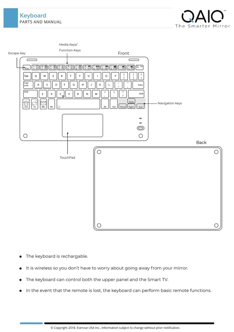
IBM 5475 User manual


-- -
--
--
-
----.
----
-
---
- - -
---
- - - =:
~
§:
Maintenance
Library
Elastic
Diaphragm
Encoded
Keyboards
and
5475
Data
Entry
Keyboard
Theory-Maintenance
Manual
SY27-0073-1

Preface
This manual covers
both
the theory
of
operation and the
maintenance for keyboards using Elastic Diaphragm
Switches.
It
is
intended for use
by
the Customer Engineer.
The manual
is
divided into two major parts: Part 1
contains the
FE
Theory
of
Operation and Part 2 contains
the
FE
Maintenance Documentation.
In
addition,
Appendix A covers information peculiar to the 5475
keyboard and its use
with
a system. This information
consists
of
keyboard layouts, connector and code charts,
diagnostic flowcharts, and differences from the basic
keyboard. Information peculiar to
other
keyboards and
their use with a system
is
covered in the using system's
documentation.
No companion or prerequisite manuals are necessary
for use with this publication.
Second Edition (March 1971)
This is a major revision of,
and
makes obsolete, SY27-0073-0.
It
includes additional line
drawings
to
enhance
both
the
theory and maintenance sections. Associated changes to
the
text
and illustrations are indicated
by
a vertical line to the left
of
the change. New
material, added
to
Parts 1 and 2, covers the new encode board and elastic diaphragm
switch assembly. These additions, being entirely new, are
not
marked with vertical lines;
they
can
be
easily located
by
use
of
the table of contents
or
the index.
Changes are periodically made
to
the
specifications herein; any such changes will be
reported
in subsequent revisions
or
Technical Newsletters.
This manual has been prepared
by
the
IBM
Systems Development Division, Publications
Center, Department EOl, Building 060, Research Triangle Park,
North
Carolina 27709.
A form for reader's comments
is
provided
at
the back
of
this publication.
If
the form
has been removed, comments may be sent to the above address.
© Copyright International Business Machines Corporation 1969, 1971

Part
1.
Theory
of
Operation
Introduction .
Functional Units
Principles
of
Operations
Key Mechanisms
Latch Key Operation
Momentary Key Operation
Typamatic Key Operation
Elastic Diaphragm Switch
Encode Circuit Board
Bail Drive Card .
Shift Key
New Encode Circuit Board and Switch Assembly
Part
2. Maintenance
Preventive Maintenance
Lubrication .
Figure Title
1-1
Keyboard: Elastic Diaphragm Encoded
(Example)
1-2 Latch Key (Normal Position)
1-3 Latch Key (Operated Position)
1-4 Latch Key (Restoring) .
1-5
Uall
Interlocks
1-6
Momentary Key (Normal Position)
1-7
Momentary Key (Operated Position) .
1-8
Typamatic Key (Single Cycle Operation)
1-9 Typamatic Key (Repeat Operation)
1-lOA Elastic Diaphragm Switch Asm. (EDS)
1-lOB Elastic Diaphragm Switch Asm. (EDS)
1-11 Elastic Diaphragm Switch Substrate
1-12 Encode Board
1-13 Encode Circuits (Example)
1-14 Restore
Uail
Interposer and Latch Interposer
Comparison
1-15
Shift Key Lock Mechanism
1-16 Redesigned Encode Board and Switch Asm.
1-1
1-1
1-1
1-1
1-1
1-1
1-4
1-4
1-6
1-7
1-9
1-9
1-10
2-1
2-1
2-1
Page
1-1
1-2
1-2
1-3
1-3
1-4
1-5
1-5
1-6
1-6
1-7
1-8
1-8
1-9
1-9
1-9
1-10
Cleaning .
Maintenance .
Checks, Adjustments, and Removals
Key Lever
Interposer
Restore Bail and Magnet Assembly
EDS
Latch
Spring and Actuator .
New Encode Board and Switch Assembly
Ball Interlock Assembly
Space Bar Assembly
Shift Key Mechanism
Appendix A.
5475
Keyboard
Index .
Contents
2-1
2-1
2-1
2-1
2-2
2-3
2-4
2-5
2-5
2-6
2-6
A-1
X-1
Illustrations
Figure Title Page
1-17 Encode Circuits (New Style Encode Board) 1-11
2-1
Latch Key Adjustments 2-2
2-2 Interposer to Guide Comb Clearance . 2-2
2-3
Dabber
Adjustment (To Lower Dabber) 2-3
2-4
Dabber
Adjustment (To Raise Dabber) 2-3
2-5
Momentary Key Interposer Overtravel 2-3
2-6 Bail Adjustments 2-4
2-7
Bail Stop Adjustment . 2-4
2-8
Latch Spring and
Actuator
Adjustment
2-5
2-9 Encode Board and Diaphragm Replacement 2-5
2-10 Ball Interlock Assembly Adjustment .
2-5
2-11 Space Bar Operating Tab Adjustment 2-6
A-1
5475 Keyboard Arrangement .
A-1
A-2
System/3 Card Code A-2
A-3
5475 Electrical and Mechanical Timings
A-3
A-4
Control Panel A-3
A-5
5475 Interface Connectors
A-4
A-6
5475 Control Panel Connectors
A-5
A-7
5475 Keyboard Diagnostic Flow Chart
A-6
iii


INTRODUCTION
The keyboard
is
a manual entry device providing coded
outputs to the using system through cable connections.
Different models'provide various codes, key configurations,
J and control keys for the using system (Figure
1-1
). A
circuit board creates
output
codes that are compatible
with the coding scheme
of
the system. The system samples
• the bit
output
lines and signals the keyboard reset. The
keyboard can be used for entering data or for inquiry
by
the use
of
the data keys. The keyboard control keys can
format data or can control functions for various
output
devices.
Keyboard interlocking prevents pressing two latch keys
at the same time or pressing a second latch key before a
keyboard cycle
is
complete. The using system locks the
keyboard when it
is
not in use.
It
is
locked when power
is
off.
Refer to the keyboard pictured in Figure
1-1
for
locations and orientations used throughout this manual.
FUNCTIONAL UNITS
The information usually found in the Functional Units
section has been incorporated in the Principles
of
Operation
section.
•
All
locations
and
directions are referenced from the
operator
•
Front
of
tho
keyboard·
Portion closest
to
the
operator
• Right
and
left of
the
keyboard -Operators right and left
• Key rows -First row
is
farthest from
the
operator
and
the
fourth row
is
tho closest
to
the
operator
I Figure 1-1. Keyboard: Elastic Diaphragm Encoded (Example)
Part
1.
Theory
of
0 peration
PRINCIPLES OF OPERATION
Key
Mechanisms
The keyboard may include three types
of
keys, depending
on
the model: latch keys, momentary keys, and typamatic
keys. A latch key provides
on·e
coded
output
to the
interface lines each time the key
is
pressed. All graphic
keys and some control keys use the latch key mechanism.
A momentary key provides an
output
to the interface only
while the key
is
held
Clown.
Most control keys or function
keys use the momentary key mechanism. When a repetitive
function
is
desired, graphic or control keys use the typamatic
key mechanism.
Latch
Key
Operation
Pressing a latch key (Figure 1-2) pivots the keylever on its
fulcrum rod. The dabber transfers the downward motion
to the interposer. A latch spring rests against the rear
of
the interposer. As the interposer moves down
at
the rear,
the latch spring moves forward over the interposer (Figure
1-3). The latch spring latches the interposer down and
closes the associated elastic diaphragm switch (EDS).
Closing an EDS makes a circuit
to
the encode circuit board,
which generates coded
outputs
and a signal indicating data
is
available.
Elastic Diaphragm Enc Kybds and 5475 Data
Entry
Kybd (3/71)
1-1

front
_..,.
____
..:..,..
... Rear
Restore Magnet
Figure 1-2. Latch Key (NormalPosition)
Restore Bail
figure
1-3. Latch Key (Operated Position)
1-2
(3/71)

When the 'data available' signal and the data character
are accepted
by
the system, power to the restore magnets
is
dropped. The keyboard restoring bail moves to the
front
of
the keyboard (under spring tension) carrying the
latched interposer with
iL
An elongated interposer pivot
hole allows the interposer to move to the front, clearing
the latch spring (Figure 1-4). The interposer return spring
forces the interposer up
off
of
the bail and behind the latch
spring. The interposer pushes the latch spring to the rear,
allowing the EDS to open.
As
the interposer moves to the rear, the interposer
projection strikes the <lobber, and pivots it from its rest
position. When the keylever
is
released, it pivots upward
and the <lobber return spring restores the <lobber to its
normal position above the interposer.
As
the bail moves to the front, it moves under all the
unoperated interposers (Figure 1-2) and prevents them
from operating. While the keyboard restore bail travels
toward its forward stop, the bail contacts (which are EDS
switches) close, providing the 'bail contact' or 'restore'
signal to the system, or keyboard logic. This indicates the
bail has traveled its full restoring stroke and the restore
magnets can again be energized. The keyboard remains .
locked and the 'bail contact' or 'restore' signal remains
until the restore bail magnets are picked and sealed.
The 'bail contact' or 'restore' signal drops the
'data
available' signal and holds it reset. These electronic inter-
locks allow the time for the EDS switch to open. Thus,
there
is
only one
output
from the keyboard for each latch
key pressed.
Figure 1-4. Latch Key (Restoring)
The keyboard
is
locked
by
the ball interlock (Figures
1-3
and 1-5) while the interposer
is
latched down. An
operated interposer goes between the interlocking balls
and takes up
the·
clearance between the balls. Other inter-
posers can
not
be operated until the first one
is
restored
because the balls can
not
separate to allow another inter-
poser to enter. The keyboard
is
locked
by
the restore
bail during restore time. Therefore, the next key cycle
can begin only when the restore magnets are again picked
and sealed.
lnte,pom•
n
c:Qo
Ball
Interlocks
Figure 1-5. Ball Interlocks
Interposer Return Spring
Elastic Diaphragm Enc Kybds and 5475 Data Entry Kybd (3/71)
1-3.

I
Momentary Key Operation
Momentary control keys do
not
provide a coded
output
to
the interface
bit
lines,
but
do activate a control line to the
keyboard interface. The momentary key interposer, unlike
the latch key interposer, has a link (Figure 1-6) that operates
on the latch spring, and the pivot hole
is
not elongated.
As the key
is
pressed, the <lobber moves the interposer
down, causing the link
to
pivot (Figure 1-6). The latch
spring closes the EDS
as
it follows the arc
ot
the link
(Figure 1-7). The interposer
is
not
latched down by the
latch spring, and the using system determines
if
a keyboard
restore cycle occurs
as
a result
of
pressing a momentary
key. The circuit through the EDS remains closed
as
long
as
the key
is
held down.
When the key
is
released, the interposer
is
restored
by
its
return spring and the link cams the latch spring away from
the EDS.
Typamatic Key Operation
When a typamatic key
is
held down with a slightly more
than
normal pressure, it permits automatic repetition
of
a
graphic, space,. or function key. Normal pressure
on
the
key causes only one operation,
as
with
a standard latch-
type key.
The typamatic keylever (Figure 1-8) has a typamatic
latch pivoting
on
the keylever at the front. When the
keylever
is
pressed, the typamatic latch downstop strikes
the
top
of
the interposer fulcrum. This
is
the normal stop
for
the
typamatic keylever, and actions
of
the <lobber,
interposer, and switch are identical to a standard latch key
Figure 1-6. Momentary Key (Normal Position)
1-4
(3/71)
mechanism. Additional pressure
on
the keylever overcomes
the typamatic latch spring tension, causing the latch to
pivot downward from the keylever. The turned-over ear
on the typamatic latch then strikes the
top
of
the interposer
projection, and holds the interposer down in the latched
position. When the restore magnet
is
de-energized during
this cycle, the restore bail moves the interposer to the front.
The turned-over ear pivots down behind the interposer
projection (Figure 1-9) and holds the interposer forward.
The interposer remains in this position, with the EDS closed,
until the key
is
released. Data
is
sampled
by
the system
until the interposer
is
restored and the EDS switch opens.
When the keylever
is
released, the interposer restores
immediately. The interposer return spring pulls the inter-
poser to the rear
of
the keyboard, where
it
strikes the latch
spring and allows the switch
to
open. The electronic circuits
complete the keyboard cycle
that
may already be in progress
by providing proper timing for the data lines and the
'data
available' signal (refer to the timing chart for the 5475 in
Appendix A).
Another method can begin a typamatic operation.
If
the keylever
is
not
pressed to its limit soon enough, a full
restore cycle occurs. The <lobber
is
out
of
position because
the keylever
is
down.
If
the keylever
is
pressed to its limit
at this time, the turned-over ear
of
the typamatic latch will
strike the interposer projection. The interposer will move
down and latch under the latch spring. As the restore
portion
of
the cycle begins, the interposer will again move
behind the turned-over ear
of
the typamatic latch and will
be held in this position until the key
is
released. The
remainder
of
the operation
is
the same
as
the first repeat
operation described.

\nterposer Return Spring
---
Latch Spring
Link
Figure 1-1. ).\omcntatY
J{eY
(Operated Fosition)
f igUfC 1-S. 'fypamatic
J{ey
(Single Cycle Operation)
ElasticDiaphragm
Enc
J{ybd>
and 5415 DataEnttY J{ybd
(3/11l
1-5

Figure 1-9. Typamatic Key (Repeat Operation)
I Elastic Diaphragm Switch
(Old
Style)
The EDS (elastic diaphragm switch assembly) consists
of
a
substrate, a separator, an elastic diaphragm, a Mylar* spacer,
a slotted clamp, a spacer, an actuator spring, a beveled
spacer, a latch spring, and a clamp (see Figures 1-lOA and
1-lOB). The substrate
is
flexible plastic, with copper-ribbon
land patterns running from the
EDS
to the encode circuit
board assembly (Figure
1-11
). The land patterns laminated
on
the substrate terminate at one end in a solder connection
to
the encode circuit board and at the other end behind a
hole in the separator. The end behind the separator hole
is
Figure 1-lOA. Elastic Diaphragm Switch Asm. (EDS)
1-6
(3/71)
Turned-Over
Ear
lnte1poser Projection
the N/O contact
of
an elastic diaphragm switch. The plastic
diaphragm
of
the switch has a laminated conductor that
is
electrically common to all the switch positions. The
separator layer, which separates the substrate and diaphragm,
contains holes aligned with each
of
these contacts. The sub-
strate, separator, and elastic diaphragm are clamped together
to the rear
of
the keylever support (Figure 1-lOB). When
a latch spring
is
released, the elastic diaphragm
is
pressed
through the hole in the separator
by
the actuator spring
projection. The diaphragm common conductor contacts
the N/O contact on the substrate, which completes the
circuit to the encode circuit board.
....,--Spacer
!+---
Actuator Spring
,....,.."'/1-+--- Spacer
Latch Spring
Clamp

Fulcrum
--
-
_.-
Actuator
Spring
Latch Spring
Figure 1-lOB. Elastic Diaphragm Switch Asm. (EDS)
I Encode Circuit Board (Old Style)
The encode circuit board (Figure 1-12) attaches to the top
of
the keyboard side frames and can be pivoted for access
to the mechanical portions
of
the keyboard. The SLD
logic circuits receive inputs from the elastic disphragm
switches to initiate outputs to the using system. Control
inputs from the using system control keyboard operations.
SLD logic encodes the inputs from the EDS into the code
of
the using system and routes these codes to the system
interface. Connection to the interface
is
through pluggable
SLD connectors at either side
of
the circuit board.
Actuator
Spring
Substrate
The elastic diaphragm switch completes a circuit through
the encode board diode matrix or logic block depending on
the model (Figure 1-13). This input ANDs with the shift
mode (uppercase or towercase) and sets the appropriate
bit
latches. The
'bit'
latch outputs are ORed
to
generate a
'data available' signal. 'Data available' indicates to the
system that a key
is
down and the
'bit'
lines are up.
In some models, the 'data available' signal
is
the hold and
reset for the
'bit'
latches. When accepting data, the system
drops its hold
on
the restore magnets. The restore bail then
operates the restore bail interposer, closing the bail contacts
(Figure 1-14), which generate a 'bail contact' signal in the
encode board. 'Bail contact' resets the
'bit'
latches.
Elastic Diaphragm Enc Kybds and 5475 Data
Entry
Kybd (3/71)
1-7

Figure 1-11. Elastic Diaphragm Switch Substrate
• •
• •
• •
N
••
2 : :
~
..
c
••
8
••
II@
I
Encode Board
Encode Board
land
Patterns
013
• •
• •
• •
• I a
•
• I u
•
~
• • d
• •
"• •
•
J13
I
r-~~
...............
....-n-~~~~~---~~~~~~~~~~~~--ril'"TT..,.,..
......
~~-.
I
002
G13
I
L-------__J
EDS
Positions
Substrate
Pin Side (Viewed
from
Rear
of
K.B.)
*Can
have
up
to
88 positions
Note
1 Some models do not have two connectors-Connector 1 will always be
In
the
tame location
Figure 1-12. Encode Board (Old Style)
1-8
(3/71)

Inputs {
from
EDS
Switches
Shift
(Upper
or
Lower Case}
A
*Note:
Some
Models
Use
Diode
Matrix
in
Place
of
SLD
Logic
Figure 1-13. Encode Circuits (Example)
Bit Latch
FL
2 Bit
4 Bit
Figure 1-14. Restore Bail Interposer and Latch Key Interposer Comparison
Bail
Drive Card
A
SMS
drive card,
mounted
below the keyboard,
is
used
to
drive the restore bail magnets. It
is
con~rolled
by
the using
system. The using system prevents the flow
of
current
through the magnets which restores the keyboard during
operation
or
locks the keyboard when
not
in use.
Shift
Key
The SHIFT key shifts the keyboard into uppercase, causing
the character key
output
to be coded differently. The
shift key operates the same
as
any momentary key. The
SHIFT key
is
not
interlocked because
other
keys
must
be
operated with it.
Some models have a SHIFT key LOCK (Figure 1-15)
that
allows continuous uppercase operation. When the LOCK
key
is
pressed, the turned-over ear pivots the latch against
the lock bar. Additional pressure causes the keylever to Figure 1-15. Shift Key Lock Mechanism
(Data
Available)
Restore
Bail
Latch
Key
lnterp~ser
Shift
Key
Elastic Diaphragm Enc Kybds and 5475 Data
Entry
Kybd (3/71)
1-9

pivot down and the latch to slide along the lock bar.
As
the latching surface
of
the latch passes the lock bar, it pivots
under the lock bar and latches in this position
as
pressure
is
released
on
the LOCK key. To release the lock, the SHIFT
key
is
pressed. The latch moves free
of
the lock bar and
returns
to
its normal position under spring tension.
The binary counter, driven
by
a free running oscillator,
generates counts
to
scan the horizontal and vertical lines
of
the switch matrix. When the scan coincides with a switch
closure, the data selector generates 'scan complete', which
stops the counter. The
output
of
each
ROS
address (counter
output)
is
stored in a 4-bit register. When 'scan
co~plete'
occurs, the bits stored in the register (A,
B, C,
and D) from
the previous
ROS
address and the bits from the present
ROS address (1, 2, 4, and 8) make up the 8 bits
of
the
character. 'Scan complete' also brings up 'any data', which
tells the using system that data.is on the
'bit'
lines. A 'reset'
line
is
generated to reset the counter.
Invalid characters are detected before the set
of
'any
data'. 'Any data'
is
timed to ensure valid data on the data
bus; and timing ensures that 'scan complete'
is
ignored,
during count transitions, to prevent false addressing.
New
Encode
Circuit Board
and
Switch
Assembly
Some models
of
the keyboard have a redesigned encode
board and switch assembly (Figure 1-16). This board
is
mounted on the rear
of
the keyboard instead
of
on the top,
and does not have a flexible substrate. The components
of
the new board are the substrate, separator, diaphragm,
switch spacer, and latch assembly. Operation
of
the switch
assembly
is
the same
as
with the old board.
The encode board portion
of
the assembly uses T2L
logic in place
of
SLD logic, and has a different theory to
produce the same
output
lines (Figure 1-17). A
ROS
(read
1-10 (3/71)
...._~----v-~~~~~--'
Note
2
Notes:
1• The Latch Spring Assembly provides
the
combined functions
of
the
Activator
and
Latch Springs
of
the
previous design.
2.
The Logic Card and Switch
are
Factory-Assembled
and
to
be
replaced
as a
unit.
Figure 1-16. Redesigned Encode Board and Switch Assembly
only storage) unit, programmed for the proper
output
code,
is
used instead
of
the
'bit'
latches, and
is
addressed
for
each
switch position. A switch matrix, a seven-bit binary counter,
and a data selector generate the ROS address and take the
place
of
the AND/OR circuits used to set
'bit'
latches.

Counter
~~c~o_u_n_t_l
___
--1-r--r------------lr-------i
Count 2
.-----i~
Clo~
Reset
Tl
---~N
i
Count 4 Spec
Count 8
Count 16
Count
32
Switch
M1-at-r-ix-
...
-----~------------
...
-=--=--=-~-=-~-1~·1--S-ca_n_C
I
...
~
....
,
p_l_e_te
_
___,
-
1~~
r , "
~
>I
~
"?
.-------1
Bit
D
+-t-t--+--
1----+-~-1-+-<~+-!4.-'4~+"4'!:
4-7
J R
Spec
>I<
~
>I<
I<
>I
>
~
>i~>
!<~>+<
&
>+<
>i
)'-
>+<>+<
~
• R
Bit
C
...______.
"r'
7
lo.I
'""
'""'
'--~~~~1-+-+-Hl-f---IEl-----f:-i-·~G_a_te~-+--+--~---a~]
R
~1----------'
J -
R
Bit
B
Bit
A
Shift
~ROS
Bitl
-------1
256X4
-----Bi-t-
2
Bit
4
Bit
8
Error
Scan Complete A
1-----------11~1------A_n_y_D_a_ta_(D_a_t_a_A_v_a_il_a_b_le_)
------iN._
_____
___.
Delayed
Bail
Forward
Figure 1-17. Encode Circuits (New Style Encode Board)
Elastic Diaphragm Enc Kybds and 5475 Data
Entry
Kybd (3/71) 1-11


PREVENTIVE MAINTENANCE
CAUTION
Remove power before performing
PM
or
removing
keyboard.
Perform preventive maintenance to the keyboard during
unscheduled interruptions when possible.
If
unscheduled
interruptions do
not
occur in a twelve
month
period, a
preventive maintenance schedule must be provided. The
keyboard can be removed from its mounting (remove
power first) for easy servicing. Cable connections on the
left and right sides
of
the keyboard, and plug-on connectors
for the drive card, make removal easy.
Lubrication
Always lubricate with number 23 grease.. Grease the
following points every twelve months:
• Keylevcr pivots
• Keylever leaf and return springs
•
Front
interposer guide combs
• Space bar shaft pivots and keylever tab
• Dobber pivots
• Space bar pivots
• Restore bail armature pivots
• Reset drive spring anchors
• Latch spring and momentary link connections
• Interposer latch spring tips
• Shift bar shaft pivots
Cleaning
Clean the unit before each
lubri~ation
and when the environ-
ment indicates it
is
necessary.
MAINTENANCE
CAUTION
In localing troubles in the circuit portion
of
the keyboard,
do
not
use a test light; it could cause damage to the
circuits. Also when using an ohmmeter, take care to
prevent shorting pins or overloading the circuits. Do
not use the ohmmeter on less
than
R X 100.0 scale.
Part
2. Maintenance
Maintenance consists
of
adjusting mechanical parts and
replacing worn parts. When troubles are in the encode
board
or
the magnet driver card, these items must be
replaced. Trouble with the EDS
may
require replacing
the separator and the diaphragm, or adjusting
or
replacing
the actuator
or
the latch spring.
Test points for troubleshooting EDS switches and the
encode board are in the keyboard logics for the using
system.
CHECKS, ADJUSTMENTS,
AND
REMOVALS
Key Lever
Checks
The keylever, when pressed, should move around its pivot
at the rear
of
the keyboard until the lever
bottoms
in the
front guide comb. When released, it should rise until the
lever strikes the upstop rod in the front comb (Figure
2-1
).
The <lobber should clear the interposer and should return
to its rest position above the interposer projection when
the key
is
released.
Note: Unused key positions require their elastic
diaphragm switches
to
be either open or closed.
If
the switches are
to
be
held open, the keylevers are
blocked
by
a plastic lockout (Part 5994922)
to
prevent
the operation
of
the interposer. Closed switches do
not
have interposers and are held closed continuously
by
the latch spring assembly.
Adjustment
There is no keylever adjustment
to
meet keylever travel
called for in the checks. Failure to
meet
these conditions
indicates some defect in the keylever operation
or
with
the associated mechanisms. Refer
to
the diagnostic
flowchart in Appendix A or the diagnostic flowchart for
the specific system.
For
<lobber clearance, refer
to
"Adjustment-Latch
Key".
Removal
1.
Loosen the two front and the two rear encode board
mounting screws, and tilt the board
to
the rear
of
the
keyboard (old style only).
2. Remove
keybutton
from the keylever
that
is
to be
replaced.
3. Remove
other
keybuttons
that
extend over the
keylever that
is
to
be replaced.
Elastic Diaphragm Enc Kybds and 5475 Data
Entry
Kybd (3/71)
2-1

Front
Guide
Comb
Figure 2-1. Latch Key Adjustments
4. Pull
out
the pivot rod
with
pliers
or
use a follower rod
to push it
out
until the keylever
is
free.
5. Raise the pivot end
of
the keylever
to
be removed and
work it
to
the rear until it clears the upstop rod. Work
the keylever
out
of
the keyboard.
6. Replace in the reverse order.
7. Perform checks and necessary adjustments.
Interposer
Checks
The interposer should be latched
by
the
EDS
latch spring
before the downward
motion
of
the keylever
is
complete.
When the keylever hits its downstop, the interposer should
have some travel left before it
bottoms
on the guide comb
slot at the rear
of
the keyboard.
Adjustment-Latch
Key
The interposer tip must clear the EDS latch spring, and must
be at least 0.005 inch above the
bottom
of
the interposer
guide comb slot (Figure 2-2) when the keylever
is
fully
operated. To obtain these conditions, the keylever must be
formed.
If
the interposer
is
not
traveling far enough, form
the keylever (Figure 2-3)
by
placing pliers across the pro-
jections provided on the keylever. Squeeze gently to obtain
the desired position
of
the <lobber.
If
the interposer
is
traveling
too
far, form the keylever (Figure 2-4)
by
placing
2-2 (3/71)
Rear Interposer
Guide
Comb
Restore
Bail
Latch Spring
f
0.005
Minimum
Gap
Figure 2-2. Interposer to Guide Comb Clearance
pliers
on
one projection and a screwdriver between the
projections then spreading the projections. Hold the screw-
driver tip against the pliers and the shank against the
opposite projection applying force to spread the projections.
The theory
of
this adjustment
is
to raise or lower the
tail
of
the keylever, thus changing the relative position
of
the <lobber.
The
travel
of
the keylever
is
not
affected.
If
the tail
is
raised, it will strike the upstop sooner and the
<lobber will be lower and closer
to
the interposer. The
opposite
is
true if the tail
is
lower; it will strike the upstop
later and the <lobber will be further from the interposer.

Needle-Nose
Pliers
{or
Duck Bills)
Figure 2-3. Dobber Adjustment (To Lower Dobber)
Keylever
Needle-Nose
Pliers
(or Duck Bills)
Screwdriver
Keylever
Figure 2-4. Dobber Adjustment (To Raise Dobber)
Adjustment-Momentary Key
Momentary key interposers must travel at least 0.025 inch
before the switch closes, and must have a minimum over-
travel
of
0.005 inch. The keylever
is
to be adjusted to
.obtain these dimensions, and
it
may be necessary to form
the momentary link to obtain the proper overtravel
(Figure 2-5).
Removal
1.
Loosen the front and rear encode board screws and tilt
the encode board up and
to
the
rear
of
the keyboard
(old style only).
2.
Remove the keylever upstop rod.
3.
Remove the spacebar rod.
4. Raise the keylevers evenly.
5. Pull
out
the interposer pivot rod with pliers or push
it
out
with a follower rod.
6. Remove the spring from the interposer to be removed.
7. Raise the pivot end
of
the interposer and remove to the
front
of
the keyboard.
8. Replace in the reverse order.
9. Perform checks and necessary adjustments.
Interposer Return Spring
Interposer
Figure
2-5.
Momentary Key Interposer Overtravel
Restore
Bail
and
Magnet Assembly
Checks
Latch Spring
Link
(Form
for
Overtravel)
The bail should clear the restored interposers when it passes
beneath them. The interposers should clear the bail when
they are latched and should be restored fully when the
magnets are
not
energized.
CAUTION
Magnet yoke nuts are
not
to
be tightened more
than
finger tight plus 1/4 turn.
Adjustments
Each bail spring should require 130
to
170 grams
of
force
to pull its end
of
the bail away from the stop with
the
magnet not energized. The top surface
of
the bail (Figure
2-6) should be 0.015
inch±
0.014 inch below the inter- 1
posers when the magnets are energized. There
is
no adjust-
ment for the
top
surface
of
the bail other than the play in
the yoke mounting holes. The restore surface
of
the bail
should be 0.015
to
0.030 inch from the restore surface
of
the interposer with the magnets energized. Adjust the
restore surface clearance
by
positioning the magnet yoke
assemblies within
the
side frames.
It
may be necessary to
form the feeler gage
to
make this adjustment
as
the magnet
yoke interferes with the gage.
Adjust the bail stops
to
allow proper restoring
of
the
interposers. Place a 0.020 inch shim between the bail and
the bail stop (Figure 2-7). When the bail
is
operated, the
interposers should restore. The interposers should
not
restore with a 0.030 inch shim between the bail and the
bail stop.
Elastic Diaphragm Enc Kybds and 5475 Data Entry Kybd (3/71)
2-3
Table of contents
Other IBM Keyboard manuals

IBM
IBM TrackPoint USB Space Saver Keyboardwith Hub User manual

IBM
IBM 3277 User manual

IBM
IBM TrackPoint User manual

IBM
IBM Preferred USB Keyboard with Hub User manual
IBM
IBM 4685-K03 Technical Document

IBM
IBM 7785 Owner's manual
IBM
IBM 3215 User manual
IBM
IBM Rapid Access III USBKeyboard User manual
IBM
IBM SK-8808 User manual
