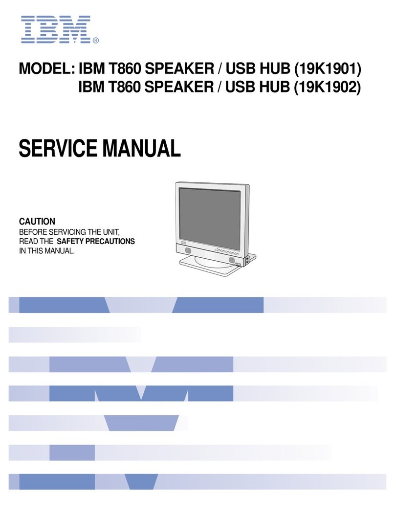
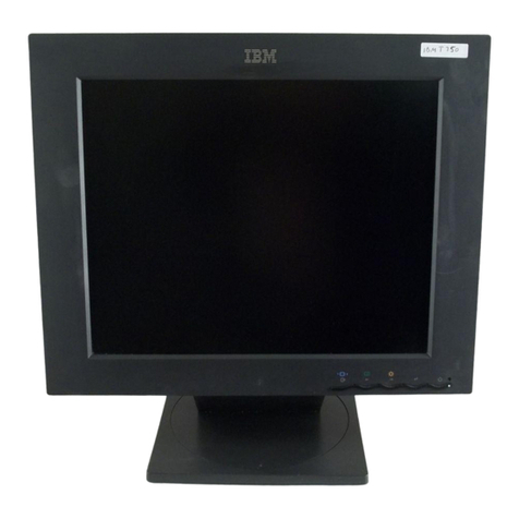
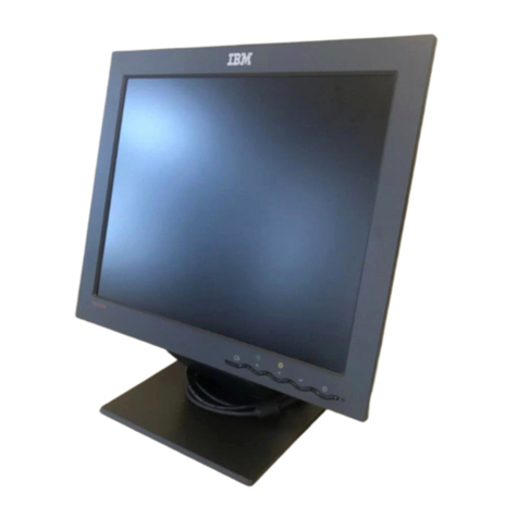
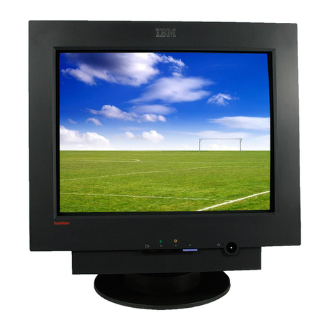
IBM 3197 C User manual

IBM
3197
Model
C Color Display Station
User's Guide
GA
18-2559-1
Part
Number
6457158
File
Number
S5250/S36/S38-06

(
(:
IBM
3197
Model C Color Display Station
User's Guide
GA18-2559-1
Part Number 6457158
File Number 85250/836/838-06

Federal Communications Commission (FCC) Statement
Warning: This equipment generates, uses, and can radiate radio
frequency energy and if not installed and used in accordance with the
instruction manual, may cause interference to radio communications.
It has been tested and found to comply with the limits for a Class A
computing device pursuant to Subpart J
of
Part 15
of
FCC Rules,
which are designed to provide reasonable protection against such
Interference when operated
In
a commercial environment. Operation
of this equipment in a residential
area
is
likely to cause Interference
In
which case the user at his own expense will be required to take
whatever measures may be required to correct the interference.
The above FCC statement applies only to those machines In the U.S.
Second Edition (July 1987)
This
major
revision obsoletes GA18-2559-0. Changes are occasionally made to
the
information herein; any such changes
will
be reported in subsequent revisions
or
Technical Newsletters.
References in this publication to IBM products, programs,
or
services
do
not
imply
that
IBM intends to make these available in all countries in which IBM operates. Any
reference to an IBM licensed program in this publication
is
not intended
to
state
or
imply
that
only IBM's licensed program may be used. Any functionally equivalent
program
may be used instead.
Publications are not stocked at the address given below. Requests
for
IBM publications
should be made to your IBM representative
or
to the IBM branch office serving your
locality.
A form for readers' comments is provided at the back
of
this publication. Ifthe form
has been removed, comments may be addressed to IBM Corporation Information
Development, Department 6R1J,
180
Kost Road, Mechanicsburg,
PA
17055 U.S.A. IBM
may use
or
distribute whatever information you supply in any way it believes
appropriate without incurring any obligation to you.
© Copyright International Business Machines Corporation
1987
c
(~)
o

(
About This Manual
Purpose
Organization
This manual is
for
operators and supervisory personnel of the IBM
3197
Model C
display station. It describes how to:
• Use each key
• Enter, modify, and remove information
• Respond to messages and
error
codes
• Perform operator tasks.
This manual contains the following information:
Chapter 1 identifies the locations and explains the functions of the switches and
controls, and the display screen (operating status line and message line).
Chapter 2 identifies the unique features of the 122-key typewriter keyboard.
Chapter 3 describes how to operate the display station using a 122-key
typewriter keyboard.
Chapter 4 identifies the unique features of the IBM enhanced keyboard.
Chapter 5 describes how to operate the display station using the IBM enhanced
keyboard.
Appendix A lists the
error
codes and the related recovery procedures.
Appendix B provides information about 122/124-key and IBM enhanced keyboard
layouts
for
languages other than
U.S.
English.
About This Manual iii

Related Publications
IBM 5250 Information Display System Planning and Site Preparation Guide,
GA21-9337, provides cable specifications to assist in planning
for
the
installation.
If You Need More Information
iv
IBM
3197
User's Guide
You may wish to refer to one of the following publications:
• IBM 3197 Model C Color Display Station Problem Solving Guide, GA18-2561.
• IBM 3197 Model C Color Display Station Setup Instructions, GA18-2558.
• IBM 3197 Display Station Description, GA18-2544.
• IBM 5250 Information Display System Functions Reference Manual,
SA21-9247.
• Creating Displays: Screen Design
Aid
and System Support Program,
SC21-7902, describes how to change the function of command keys.
r\
U
C
·
"\
'I _ I

Contents
Chapter 1. Becoming
Familiar
with Your Display Station
1-1
Switches and Controls
1-2
Power Switch 1-3
Power-On Light
1-3
Brightness Control
1-3
Security Keylock
1-3
Adjusting Angle of the Video Element 1-4
Adjusting Keyboard Slope 1-5
Display Screen
1-6
Symbols on the Operating Status Line 1-7
Symbols in Normal Communication Mode
1-7
Symbols in Setup Mode 1-10
Symbols in Printer Setup Mode 1-13
Chapter
2.
The 122-Key Typewriter Keyboard
2-1
Keyboard Layout of the
U.S.
English 122-key Typewriter Keyboard
2-1
Key Functions 2-3
System Request 2-4
Attention 2-4
Clear 2-5
Erase Input 2-5
Print 2-5
Help 2-5
Hex 2-5
Play 2-6
Test 2-6
SetUp 2-6
Printer Setup Mode 2-6
Record 2-7
Pause
2-7
Character Backspace 2-8
Field Advance 2-8
Field Exit 2-8
Shift Lock 2-9
Shift 2-9
Reset 2-9
Quit 2-9
Enter 2-9
Data Entry 2-10
Field Backspace
2-12
("
Duplicate
2-12
Jump
2-12
New Line 2-13
Insert Mode 2-13
Contents V

vi
IBM
3197
User's Guide
----""
---~-----""-----
-"-~--~--"------~----
-"---"-"-"----"~-"
Delete 2-13
Cursor Movement 2-14
Roll 2-14
Home
Rule
Field+
Field-
2-14
2-14
2-16
2-16
Numeric 2-17
Command 2-18
Setup Mode 2-19
Printer Setup Mode
2-21
Katakana-Unique Shift Keys (124-Key Keyboard) 2-22
Chapter
3.
Operations Using the 122-key Typewriter Keyboard
3-1
Modes
3-1
Test Mode
3-1
Normal Communication Mode
3-1
Setup Mode
3-1
Record Mode
3-2
Play Mode
3-2
Printer Setup Mode 3-2
Setup Mode Operation 3-3
Offline Setup Functions 3-3
Select the Terminal Mode 3-4
One-Display Mode Operation 3-6
Two-Display Mode Operation 3-6
Display-Printer Mode Operation 3-7
Select the Multinational Character Set
3-8
Set the Keyboard
ID
3-9
Set Station Address 1 3-10
Set Station Address 2
3-11
Set the Printer Address 3-13
Online Setup Functions 3-15
Select Ruler Style 3-16
Display Dim Interval Adjustment 3-17
Adjust Alarm Volume 3-18
Adjust Clicker Volume 3-19
Enable/Disable Clicker Action 3-20
Enable/Disable Cursor
Blink
3-21
Select Cursor Style 3-22
Enable/Disable Extended Display 3-23
Enable/Disable Cursor Locator (Row/Col) 3-24
Turn-off Color Mode (Limit Color) 3-25
Record Mode Operation 3-26
Assigning Keystroke Sequences to Command Keys 3-26
Play Mode Operation 3-29
Playing Back Keystroke Sequences Assigned to Command Keys 3-29
Record/Play Exercise 3-30
Printer Setup Mode Operation 3-33
Specifying Printer Functions
3~33
Cancelling Printing Operation 3-34
Inquiring Printer Status 3-34
Display-Printer Mode Selection 3-35
Offline Printer Setup Mode Operation 3-36
o
10.
'=J

Online Printer Setup Mode Operation
3-37
Specifying Character Pitch 3-38
Specifying Line Pitch 3-39
Specifying Print Quality 3-40
Chapter
4.
The IBM Enhanced Keyboard
4-1
Keyboard Layout of the
U.S.
English IBM Enhanced Keyboard
4-1
Key Functions 4-3
System Request 4-4
Attention 4-4
Clear 4-5
Print 4-5
Help 4-5
Hex 4-5
Play 4-5
Test 4-5
SetUp 4-6
Printer Setup Mode
4-6
Record 4-6
Pause 4-7
Character Backspace 4-8
Field Advance
4-8
Field Backspace 4-8
Field Exit 4-8
CapsLock 4-9
Shift
4-9
Reset 4-9
Quit 4-9
New Line 4-9
Enter 4-10
Data Entry 4-10
Insert Mode
4-11
Duplicate
4-11
Home 4-12
Page Up and Page Down 4-12
Jump 4-12
Rule 4-12
Erase Input
4-12
Delete 4-13
Cursor Movement 4-13
Double Speed Cursor 4-13
Field+
4-14
Field-
4-14
Numeric 4-15
Function 4-16
Setup Mode 4-17
Printer Setup Mode 4-19
Katakana-Unique Shift Keys (IBM Enhanced Keyboard)
4-21
Chapter
5.
Operations Using the IBM Enhanced
~eyboard
5-1
Modes
5-1
Test Mode
5-1
Normal Communication Mode
5-1
Setup Mode
5-1
Contents vii

Record Mode
5-1
Play Mode 5-2
Printer Setup Mode 5-2
Setup Mode Operation 5-3
Offline Setup Functions 5-3
Select the Terminal Mode 5-4
One-Display Mode Operation 5-6
Two-Display Mode Operation 5-6
Display-Printer Mode Operation 5-7
Select the Multinational Character Set 5-8
Set the Keyboard
10
5-9
Set Station Address 1 5-10
Set Station Address 2
5-11
Set the Printer Address 5-13
Online Setup Functions 5-15
Select Ruler Style 5-16
Display Dim Interval Adjustment
5-17
Adjust Alarm Volume 5-18
Adjust Clicker Volume 5-19
Enable/Disable Clicker Action 5-20
Enable/Disable Cursor
Blink
5-21
Select Cursor Style 5-22
Enable/Disable Extended Display 5-23
Enable/Disable Cursor
locator
(Row/Col) 5-24
Turn-off Color Mode
(limit
Color) 5-25
Record Mode Operation 5-26
Assigning Keystroke Sequences to Function Keys 5-26
Play Mode Operation 5-29
Playing Back Keystroke Sequences Assigned to Function Keys 5-29
Record/Play Exercise 5-30
Printer Setup Mode Operation 5-35
Specifying Printer Functions 5-35
Cancelling Printing Operation 5-36
Inquiring Printer Status 5-36
Display-Printer Mode Selection
5-37
Offline Printer Setup Mode Operation 5-39
Online Printer Setup Mode Operation 5-40
Specifying Character Pitch
5-41
Specifying
line
Pitch 5-42
Specifying Print Quality 5-43
Appendix A.
Error
Codes and Recovery Procedures
A-1
OOXX
(Error Codes Appearing at Position B) A-2
90XX (Error Codes Appearing in Position A
or
C)
A-6
XXX
(Alpha Characters Appearing at Position
C)
A-8
Appendix
B.
Keyboard Layouts
for
Languages Other Than U.S. English
B-1
Glossary
X-1
Index
X-3
viii
IBM 3197 User's Guide
c

(
Figures
1-1. Locations of Switches and Controls
1-2
1-2.
1920
Character Screen Format
1-6
1-3. Operating Status Line Symbols in Normal Communication Mode 1-7
1-4.
Symbols in Setup Mode
1-10
1-5. Symbols
for
Printer Setup Mode 1-13
2-1.
IBM
3197
122-key Typewriter Keyboard Layout (U.S. English) 2-2
2-2. Relationship between Shift Status and Keytop Character 2-22
3-1. Selection of Print Functions 3-37
4-1. IBM
3197
IBM Enhanced Keyboard Layout (U.S. English)
4-2
4-2. Relation Ship between Shift Status and Keytop Character
4-21
5-1. Selection of Print Functions 5-40
8-1. Austrian/German Keyboard 8-2
8-2. 8elgian Keyboard 8-3
8-3. Canadian French Keyboard 8-4
8-4. Danish Keyboard
8-5
8-5. Finnish/Swedish Keyboard 8-6
8-6. French (AZERTY) Keyboard 8-7
8-7. Italian Keyboard 8-8
8-8. Japanese Katakana Keyboard 8-9
8-9. Norwegian Keyboard 8-10
8-10. Portuguese Keyboard 8-11
8-11. Spanish Keyboard 8-12
8-12. Spanish-Speaking Keyboard 8-13
8-13. Swiss-8i1ingual-French Keyboard 8-14
8-14. Swiss-8i1ingual-German Keyboard 8-15
8-15. U.K. English Keyboard 8-16
8-16. Dutch Keyboard 8-17
( ....
. .
-~
Figures
ix

o
o
x IBM 3197 User's Guide

Chapter 1. Becoming Familiar with Your Display Station
Your display station is made up of three workstation elements: video, logic, and
keyboard elements. Each element can be easily disconnected and replaced if
you have operating problems.
The display station can attach
either
of the following two types of keyboard
elements.
• 122/124-key Typewriter Keyboard (122-keyfor the
U.S.
and other countries,
124-key
for
Japan).
• IBM Enhanced Keyboard (102-key
for
the U.S., 103-key
for
countries other
than the U.S., 104-key
for
Japan).
This manual describes the functions and operations of the 3197 display station
using the U.S. English 122-key typewriter keyboard and the U.S. English 102-key
IBM enhanced keyboard.
For the key-top nomenclatures and keyboard layouts
for
countries other than the
U.S., refer to Appendix
B,
"Keyboard Layouts
for
Languages Other than
U.S.
English."
Chapter
1.
Becoming
Familiar
with
Your
Display
Station
1-1

Switches and Controls
Figure
1-1
shows the locations of switches and controls on the
display
station.
Brightness Control
Figure 1-1. Locations of Switches and Controls
Video Element
Power-On Light
Power Switch
Logic Element
Security
Key
Keyboard
Element
Note:
There
are
two
different types of keyboards. Figure
1-1
shows
the
122-key
typewriter
keyboard. The
other
type
is
the IBM enhanced keyboard.
Warning: An
improperly
wired
outlet
or
plug can place
hazardous voltages on accessible metal parts of this
display
station. The
power
cord and plug (when supplied) on
your
display
station have been approved
for
use with this
display
station and
meets'the necessary testing
laboratory/test
house standards. For
your
safety, the
power
cord and plug
must
be connected to a
properly
wired and grounded outlet. The customer is responsible
for
the
outlet
and plug
wiring.
If
it
becomes necessary to change the
power
cord
or
plug
or
if the
outlet is
improperly
wired, have the change made
according
to
local
or
national code. A
new
power
cord may be
ordered
from
your
IBM sales representative.
1-2 IBM 3197 User's
Guide
o
C'
I,',
j

Power Switch
Power-On
Light
Power-On Light
Brightness Control
~
I
Security Keylock
The function of each switch
or
control is described below.
When the switch lever is moved to the right (toward I), the display station's
power is turned on. Moving the lever to the left (toward
0)
turns the display
station's power off.
When you power
on
the display station, tests will run to make sure all elements
are operating
as
they should. If there are any problems during these tests, an
error
code appears
on
the operating status line (see Figure 1-2), and
an
alarm
may sound. See Appendix
A,
"Error
Codes and Recovery Procedures"
for
a
description of the
error
codes.
When the power switch is set to I(on), this indicator lights.
Turning this knob counterclockwise dims the screen. Turning it clockwise
brightens the screen.
When the security key is in the locked position, the security keylock prevents
anyone from entering
or
viewing data
on
the display screen and
a)(
~,
symbol
appears on the operating status line (bottom line of the display screen.)
When a printer is attached to the display station and is in operation, even
if
the
security key is locked, the
printer
can receive and
print
data from the host
system.
To unlock the keylock and operate the display station, insert the key and turn
it
clockwise until
it
stops. The key can be removed from the keylock in either the
locked
or
the unlocked position.
Chapter
1.
Becoming
Familiar
with
Your Display Station 1-3

-,--
---------- -
---
--
-
~~
--
Adjusting
Angle
ot
the
Video Element
The video element can be rotated
90
degrees to the right or the left.
The video element can also be tilted
up
or down.
1-4 IBM 3197 User's Guide
',I
-
-------
-----------
---
',I
',I
If
1;11>"
i
~/

('-
(
Adjusting Keyboard Slope
You can select two keyboard angles
for
both types of keyboards.
To adjust the keyboard to the highest angle, turn the keyboard
over
and
flip
the
legs down from the underside of the keyboard. The legs lock into place.
With the legs locked into the keyboard, the keyboard sits at the minimum angle.
Chapter
1.
Becoming
Familiar
with
Your
Display Station 1-5

Display Screen
Data Area
Separator Line
Operatina Status
-----------------~---
Your display screen is divided into two basic areas: data area and operating
status area.
The data area is used to display the data received either from
your
keyboard
or
the host system. The data area can display up to
1920
characters (24
lines
of
80
characters). and also includes a message line at the bottom of the area. The
message line is used to display messages from the host system
or
to display the
error
codes.
The area below the separator line is the operating status line and indicates the
status of your display station
or
the attached printer.
Figure
1-2
shows the standard format
(1920
characters) of
your
display screen.
Figure 1-2. 1920 Character Screen Format
1-6 IBM 3197 User's Guide
o

(-
Symbols on the Operating Status Line
The various symbols appearing on the operating status line are used to indicate:
• Operational status of the display station
• Operational errors
or
machine failures detected by
your
display station
• Selection of the available functions.
The symbols available
for
the operating status line vary depending on the
modes: normal communication, setup, record/play and printer setup. The
following sections describe the location and the meanings of the symbols in
normal communication, setup, and printer setup modes.
For the symbols in record/play mode, refer to "Record/Play Operation" in
Chapter 3
for
the 122-key typewriter keyboard and Chapter 5
for
the IBM
enhanced keyboard.
Symbols in Normal Communication Mode
IN
r·:~.1
The symbols that are displayed on the operating status line during
communication with the host system are shown in Figure 1-3.
,.....----
Keyboard Shift/Capslock
Ir
Katakana Shift
Ll,n
..
n
)(
'.~
KKK
LLL
EEEE
,1,·.
-~
..
.,i'iiL
..
:r
M
RR/CCC
i
..
J
I
1
Error
Code
'----
Link Error Count
Keyboard Error
Count Cursor Locato
Keylock
Input Inhibit Character Set Selection
Message Waiting2
(See
Note1
)
Message Waiting1
'--
Dim Indicator
-Diacritic Mode
Logical Display Station Number
(See
Note 2)
S stem Available
y
Notes:
1.
If
you select one-display
or
display
printer
mode (see Chapter 3
or
5 for
more
information), the Message Waiting 2 does
not
appear.
2.
If
you select two-display mode, the active
logical
display station
number
(1
or
2)
will
be
indicated.
Figure 1-3. Operating Status Line Symbols in Normal Communication Mode
Chapter
1.
Becoming
Familiar
with
Your
Display
Station
1-7

Symbol
~
N
or
,
~
or
,
)::
-;
:
KKK
LLL
EEEE
....
The following table explains the operating status line symbols for normal
communication mode and the actions to take, if required.
Symbol
Name
MeaninglAction
System The host system connected to
your
display station is operating and
Available available.
Logical Indicates which logical display station is currently active. (Two-display
Display mode only).
Station
Number
Message The blank symbol (
;)
indicates that the host system has one
or
more
Waiting 1 messages
for
logical display station 1 and the display screen
for
logical
display station 1 is active. If logical display station 1 is inactive, the
symbol is a solid one ( ,
).
Message The blank symbol ( r)indicates that the host system has one or more
Waiting 2 messages
for
logical display station 2 and the display screen
for
logical
display station 2 is active.
If logical display station 2 is inactive, the symbol is a solid one (
i'
).
Input Inhibit Your input will not be accepted by the system.
This symbol appears when:
• The host system is processing
your
input.
• The host system is very busy.
• An
error
condition was recognized by the host system.
Note: If the condition is not an
error
and this symbol remains for
an
abnormal length of time, contact your supervisor.
Keylock The security key of
your
display station is locked. Nothing can be
Locked displayed until
it
is unlocked.
Keyboard Indicates the
number
of keyboard errors since you set
your
display
Error
Count station power switch to I (on). (Appears only when the extended
display function is enabled.)
Link
Error
Indicates the
number
of
link
parity errors since you set your display
Count station power switch to I (on). (Appears only when the extended
display function is enabled.)
Error
Codes A four-digit number. These
error
codes define your operational errors.
A short audible alarm sounds.
Refer to Appendix A,
"Error
Codes and Recovery Procedures" to clear
errors.
Keyboard The keyboard is in upshift.
Shift
Katakana Shift The keyboard is in Katakana shift.
(Only
for
users who have a Katakana keyboard.)
Insert Indicates that you pressed the Ins (Insert) key.
Diacritic Mode Indicates that
your
display station is in diacritic mode. This symbol
appears when you press an accent key: circumflex ( A
),
grave accent
( .
),
tilde ( -
),
cedilla ( ,
),
diaresis (
..
),
or
acute accent (
-).
Diacritic
mode is a function of the host system program and not of the display
station. To find out how to use diacritic mode, see
your
system operator
or
the system program manual.
1-8 IBM 3197 User's Guide
, \
O
~"'"

Symbol Symbol Name MeanlnglAction
Dim Indicator Indicates that you have not pressed any key
for
2,5,
10
or
20
minutes
depending on the setting of the display dim interval adjustment in setup
mode (either offline
or
online setup mode). (The screen is blank, except
the operating status line.)
Press any key to restore the original display image.
M Multinational Indicates when one of the following is selected in test mode
or
when the
Character Set extended display is enabled:
• The multinational character set
• A country-specific character set.
RR/CCC Cursor Indicates the row and column where the cursor is currently positioned.
Locator
Chapter
1.
Beconling
Familiar
with Your Display Station 1-9
Table of contents
Other IBM Monitor manuals