IBM 5150 Owner's manual

April 2011
IMPORTANT
1. The motherboard described in this document is the
first motherboard, the 16KB-64KB one.
Examples:
* Pages 200-3 and 200-4: Do not apply to the later
64KB-256KB motherboard (different bank size).
* Page 4-7: Part number shown for the system board
(motherboard) is for the 16KB-64KB one.
2. If the BIOS on the 16KB-64KB motherboard has
been upgraded to the third revision one, then the
switch settings shown for SW2 (“switch 2”, on pages
5-6 and 5-8) on the motherboard no longer apply.
The BIOS revision can be determined by examination of
the seven digit number on motherboard chip U33.
First revision: 5700051
Second revision: 5700671
Third revision: 1501476


---
-
--
---
-
---
-----
- --
---
----
Personal Computer
-----
Hardware Reference
--_.-
Library
Hardware
Maintenance
and
Service

FEDERAL
COMMUNICATIONS
COMMISSION
RADIO
FREQUENCY
INTERFERENCE
STATEMENT
WARNING: This equipment has been certified
to
comply with the
limits for a Class B computing device, pursuant
to
Subpart J
of
Part
~
15
of
FCC rules. Only peripherals (computer
input/output
devices,
terminals, printers, etc.) certified
to
comply with the Class B limits -
may be attached
to
this computer. Operation with non-certified
peripherals
is
likely to result in interference
to
radio and TV
reception.
Associated Documentation
• Guide
to
Operations, Part 6025003
• Technical Reference, Part
6025008
• BASIC, Part 6025013
First Edition (August 1981)
Changes are periodically made
to
the information herein; these changes will be
incorporated in new editions
of
this publication.
Products are not stocked at the address below. Requests for copies
of
this
product and for technical information about the system should be made to
your authorized
IBM
Personal Computer Dealer.
A Product Comment Form
is
provided at the back
of
this publication.
If
this
form has been removed, address comment to:
IBM
Corp., Personal Computer,
P.O. Box 1328, Boca Raton, Florida 33432.
IBM
may use or distribute any
of
the information you supply in any way it believes appropriate without incurring
any obligations whatever.
© Copyright International Business Machines Corporation 1981
PREFACE
The Hardware Maintenance and Service manual
is
the publication
you
use
to
isolate and repair any failure
of
a Field Replaceable
Unit
(FRU)
.
.
.-.....,
The user should have training on the
IBM
Personal
Computer
and
be familiar with the Triplett Model 310 Multimeter*
(or
equivalent).
This manual
is
organized into ten (10) major sections:
• Section 0 - How-to-Use
• Section 1 -
Introduction
• Section 2 - Problem Isolation (PICs)
• Section 3 - Removal/Replacement
• Section 4 - Parts Catalog
• Section 5 - Locations
• Section 6 - Preventive Maintenance (PM)
• Section 7 - Reserved
• Section 8 Glossary
• Section 9 - Index
The "Problem Isolation" section
of
this manual provides step-by-step
instructions
that
aid the user in identifying the failing FRU. When
the
FRU
has been identified, the "Removal/Replacement" section
provides all the necessary information
to
complete the repair
activity (i.e., adjustments, replacements, etc.).
This manual also provides operational instructions, hardware and
design information only
to
the
extent
necessary
to
locate the failing
FRU. Complete "Operating Instructions" can be found in "Guide to
Operations",
IBM
Part 6025003. Hardware design and interface
information can be found in "Technical Reference",
IBM
Part
6025008.
*Manufactured
by
Triplett Corporation, Bluffton, Ohio 45817

Notes:
ii
CONTENTS
SECTION
O.
HOW-TO-USE
0-1
SECTION 1. INTRODUCTION .
1-1
~SECTION2.
PROBLEM ISOLATION
2-1
~
SECTION 3.
SECTION 4.
SECTION 5.
SECTION 6.
SECTION 7.
SECTION 8.
SECTION 9.
Start . 010-1
Power 020-1
System Board 100-1
Memory.
200-1
Keyboard 300-1
Display (Monochrome) 400-1
Display (Color/Graphics) 500-1
Diskette Drive 600-1
Parallel Printer
Adapter.
900-1
Asynchronous Communications Adapter
1100~1
Game Control Adapter . 1300-1
Printer 1400-1
REMOVAL/REPLACEMENT
3-1
PARTS CATALOG
4-1
WCATIONS.
5-1
PREVENTIVE MAINTENANCE
(PM)
6-1
RESERVED
7-1
GLOSSARY
8-1
INDEX.
9-1
iii

Notes:
iv
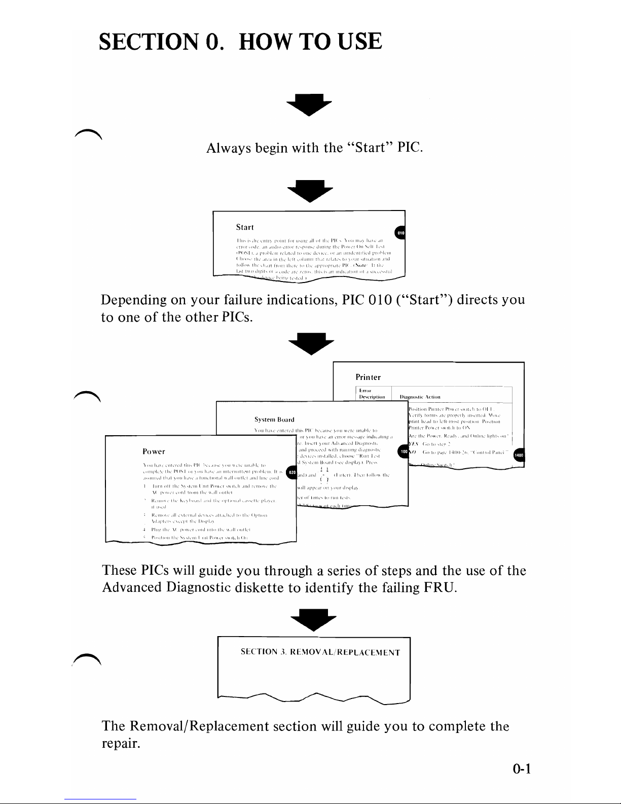
SECTION
O.
HOW
TO
USE
Always begin
with
the
"Start"
PIC.
Start
,I
II
I'I{
\,11
1'1
I'
Depending on
your
failure indications,
PIC
010
("Start")
directs
you
to
one
of
the
other
PICs.
Printer
I"""
J)('''''I'I'""
I)'''gn",tl<
\(110"
,,,,,,,1
[,'1,""\'"
."ll"
,
Power
I'll
",I
I
"
I
1'1'1,
\f
1"\
These PICs will guide
you
through
a series
of
steps and the use
of
the
Advanced Diagnostic diskette
to
identify the failing FRU.
SHTIO'-'
.j.
RBIOV.\L
InI'L\(T\lLNT
The Removal/Replacement section will guide
you
to complete the
repair.
0-1
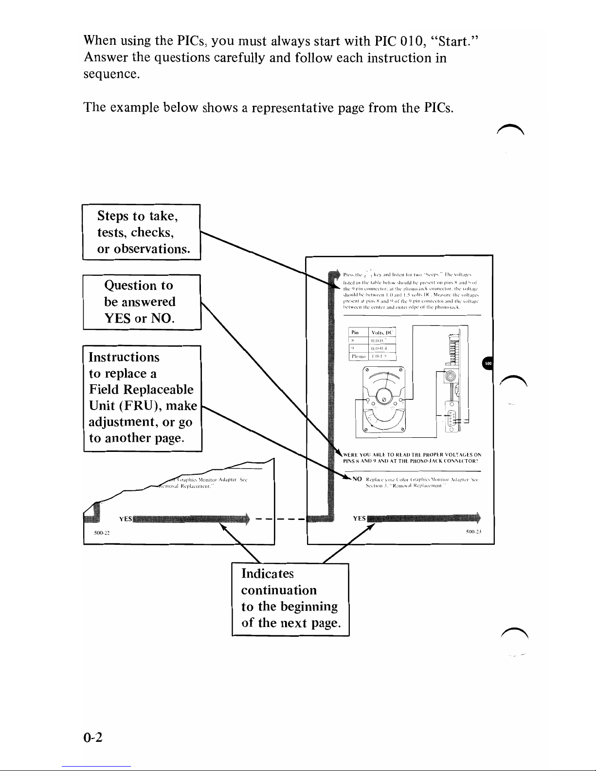
When using
the
PIes,
you
must always start
with
PIe
010,
"Start."
Answer
the
questions carefully and follow each instruction in
sequence.
The example below shows a representative page from the PIes.
Steps
to
take,
tests, checks,
or
observations.
Question to
be answered
YES
or
NO.
Instructions
to
replace a
Field Replaceable
Unit (FRU), make
adjustment,
or
go
to
another
page.
wun YOU
AIILl
TO IU
~IJ
ll1l
PROPI-R
VOLl
\(,[
S
or-.
Pl'\JS)' ,ANIJ
~
A'\IJ
AT
THI-
PllOI\,O·J.\t
K
COI\,~1
(TOl{"
yES
______
IIIl!E
..
Indicates
continuation
to
the beginning
of
the
next
page.
0-2

Special Tools
The following special tools are required
to
service the IBM
Personal Computer.
~
A.
A
meter
similar
to
the
Triplett model 310*.
~
B.
A tweezer-type module puller similar
to
the
one
shown below.
(Used for removal
of
the
16KB Memory Expansion Kit.)
*Manufactured by the Triplett Corporation, Buffton, Ohio
45817
0-3

Notes:
0-4

SECTION 1. INTRODUCTION
The
IBM
Personal
Computer
is
a powerful small
computer
which
offers a wide variety
of
options
to
give the user
the
ability
to
tailor his system
to
meet his needs now, and growth potential for
~the
future.
IBM Monochrome Display
Diskette Drives
(A and
B)
System Unit
Keyboard
Matrix Printer
The System Unit contains
the
processor and can house two optional
5-1/4" Diskette Drives. The System Unit also contains
five
expansion
slots
for
optional adapters
or
memory expansion options.
Input
to
the System Unit
is
via an 83-key Keyboard which includes a
~
numeric keypad and 10 function keys. The Keyboard is connected
with a six foot coiled cable which allows the Keyboard
to
be moved
to
a comfortable operating position.
1-1

The optional
IBM
80
CPS
Matrix Printer features 80 character
per
second, bi-directional printing. Characters can be printed normally,
enlarged, condensed,
or
emphasized. The characters
or
graphics can
be printed on multi-part forms in widths from
4"
to
10".
Other
options available for the
IBM
Personal Computer are:
•
IBM
Monochrome Display
• Color/Graphics Adapter
• Asynchronous Communications Adapter
• Game Control Adapter
• Memory Expansion Options
1-2
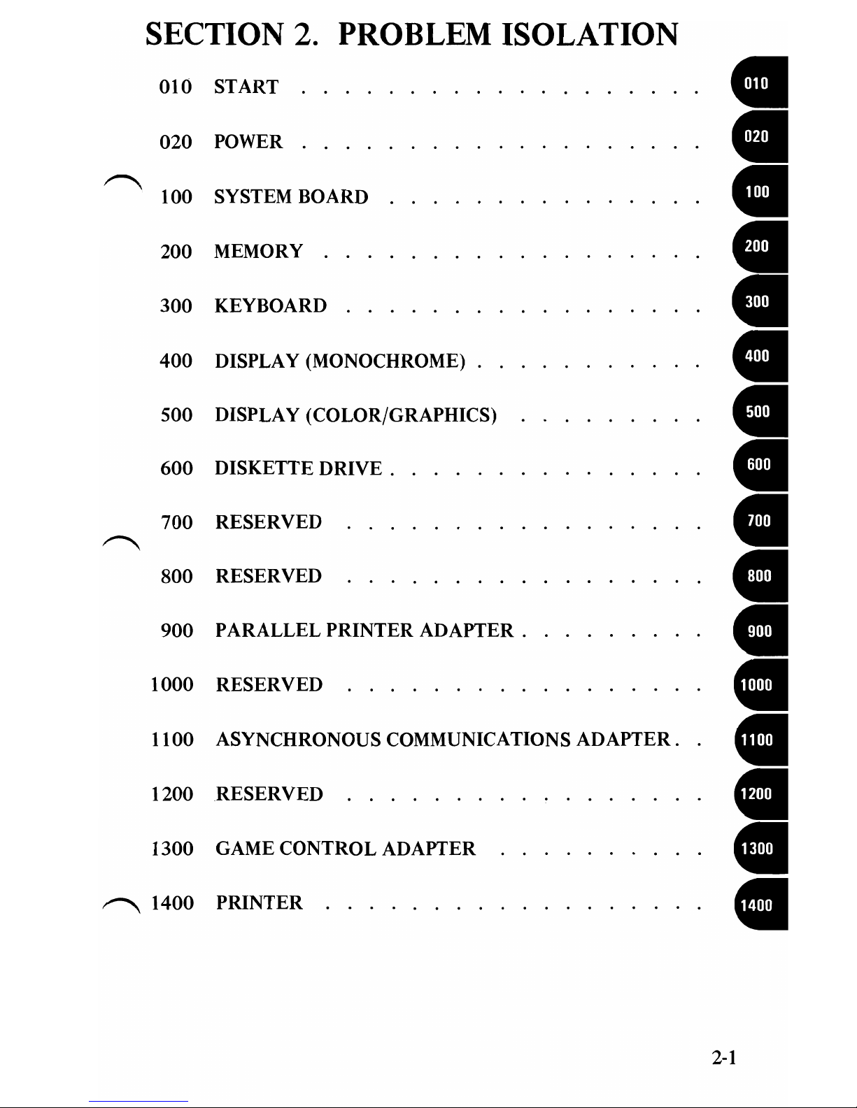
SECTION 2. PROBLEM ISOLATION
010 START •
020 POWER
~
•
100 SYSTEM BOARD •
200 MEMORY •
300 KEYBOARD
400 DISPLAY (MONOCHROME) . •
•
CI
500 DISPLAY (COLOR/GRAPHICS)
600 DISKETTE
DRIVE.
•
700 RESERVED
~
•
800 RESERVED •
900 PARALLEL PRINTER
ADAPTER.
•
1000 RESERVED . . . . . . . . . •
1100 ASYNCHRONOUS COMMUNICATIONS
ADAPTER.
•
1200 RESERVED . . . . .
..
•
1300 GAME CONTROL ADAPTER •
~
1400 PRINTER . . . .
....
•
2-1

Notes:
2-2

010-1

In order to continue,
you
must have the following minimum
components:
1.
System Unit
2.
Keyboard
3.
Input
device
('\
• Diskette Drive and Advanced Diagnostic diskette or
• Cassette player and Advanced Diagnostic
cassette.-
4.
Output
device
• Display
or
• Printer -
"'"
..
':.'~
..
--~....
..
-----
....
@
~
DO
THE SWITCH SETTINGS ACCURATELY REFLECTTHE
CONFIGURATION
OF
YOUR SYSTEM? (SEE SECTION 5,
"LOCATIONS",
FOR
THE PROPER SWITCH SETTINGS.)
NO
If
the configuration has changed, be sure the device
which
was
changed
is
not
the
cause
of
your
failure.
~
Set the switches
to
reflect the present configuration.
YES
010-2

1.
Position the System Unit Power switch
to
the
Off
position •
and remove the
AC
power cord from the wall outlet. I I
2.
Remove all non-IBM devices except the display
or
optional
cassette player.
3. Turn
the
Contrast and Brightness controls fully clockwise.
4. See
that
all connectors are installed securely and in their
proper locations.
Display Power Display Signal
(IBM Display Only)
(IBM
Display Only)
Keyboard
ARE ALL CONNECTORS INSTALLED SECURELY AND
IN THE PROPER LOCATIONS?
NO Reconnect or repair the connectors.
If
this has
not
corrected
your
failure, go
to
the
next
page.
YES
010-3
Other manuals for 5150
3
Table of contents
Other IBM Motherboard manuals


Popular Motherboard manuals by other brands


Supero
Supero A1SAi-2550F user manual

Gigabyte
Gigabyte GA-AB350M-HD3 user manual

Benchmark
Benchmark Power Gauge EV2050/H manual

MSI
MSI MAG B760M MORTAR MAX WIFI user manual

Giga-Byte Communications
Giga-Byte Communications GA-Z270X-Gaming 7 user manual

GIGA-BYTE TECHNOLOGY
GIGA-BYTE TECHNOLOGY GA-B250M-HD3 user manual